EP1664238B1 - Grün emittierende led - Google Patents
Grün emittierende led Download PDFInfo
- Publication number
- EP1664238B1 EP1664238B1 EP04786852.6A EP04786852A EP1664238B1 EP 1664238 B1 EP1664238 B1 EP 1664238B1 EP 04786852 A EP04786852 A EP 04786852A EP 1664238 B1 EP1664238 B1 EP 1664238B1
- Authority
- EP
- European Patent Office
- Prior art keywords
- led according
- led
- phosphor
- range
- mol
- Prior art date
- Legal status (The legal status is an assumption and is not a legal conclusion. Google has not performed a legal analysis and makes no representation as to the accuracy of the status listed.)
- Expired - Lifetime
Links
Images


Classifications
-
- C—CHEMISTRY; METALLURGY
- C09—DYES; PAINTS; POLISHES; NATURAL RESINS; ADHESIVES; COMPOSITIONS NOT OTHERWISE PROVIDED FOR; APPLICATIONS OF MATERIALS NOT OTHERWISE PROVIDED FOR
- C09K—MATERIALS FOR MISCELLANEOUS APPLICATIONS, NOT PROVIDED FOR ELSEWHERE
- C09K11/00—Luminescent materials, e.g. electroluminescent or chemiluminescent
- C09K11/08—Luminescent materials, e.g. electroluminescent or chemiluminescent containing inorganic luminescent materials
- C09K11/59—Luminescent materials, e.g. electroluminescent or chemiluminescent containing inorganic luminescent materials containing silicon
-
- H—ELECTRICITY
- H10—SEMICONDUCTOR DEVICES; ELECTRIC SOLID-STATE DEVICES NOT OTHERWISE PROVIDED FOR
- H10H—INORGANIC LIGHT-EMITTING SEMICONDUCTOR DEVICES HAVING POTENTIAL BARRIERS
- H10H20/00—Individual inorganic light-emitting semiconductor devices having potential barriers, e.g. light-emitting diodes [LED]
- H10H20/80—Constructional details
- H10H20/85—Packages
- H10H20/851—Wavelength conversion means
- H10H20/8511—Wavelength conversion means characterised by their material, e.g. binder
- H10H20/8512—Wavelength conversion materials
-
- C—CHEMISTRY; METALLURGY
- C09—DYES; PAINTS; POLISHES; NATURAL RESINS; ADHESIVES; COMPOSITIONS NOT OTHERWISE PROVIDED FOR; APPLICATIONS OF MATERIALS NOT OTHERWISE PROVIDED FOR
- C09K—MATERIALS FOR MISCELLANEOUS APPLICATIONS, NOT PROVIDED FOR ELSEWHERE
- C09K11/00—Luminescent materials, e.g. electroluminescent or chemiluminescent
- C09K11/08—Luminescent materials, e.g. electroluminescent or chemiluminescent containing inorganic luminescent materials
- C09K11/0883—Arsenides; Nitrides; Phosphides
-
- C—CHEMISTRY; METALLURGY
- C09—DYES; PAINTS; POLISHES; NATURAL RESINS; ADHESIVES; COMPOSITIONS NOT OTHERWISE PROVIDED FOR; APPLICATIONS OF MATERIALS NOT OTHERWISE PROVIDED FOR
- C09K—MATERIALS FOR MISCELLANEOUS APPLICATIONS, NOT PROVIDED FOR ELSEWHERE
- C09K11/00—Luminescent materials, e.g. electroluminescent or chemiluminescent
- C09K11/08—Luminescent materials, e.g. electroluminescent or chemiluminescent containing inorganic luminescent materials
- C09K11/55—Luminescent materials, e.g. electroluminescent or chemiluminescent containing inorganic luminescent materials containing beryllium, magnesium, alkali metals or alkaline earth metals
-
- C—CHEMISTRY; METALLURGY
- C09—DYES; PAINTS; POLISHES; NATURAL RESINS; ADHESIVES; COMPOSITIONS NOT OTHERWISE PROVIDED FOR; APPLICATIONS OF MATERIALS NOT OTHERWISE PROVIDED FOR
- C09K—MATERIALS FOR MISCELLANEOUS APPLICATIONS, NOT PROVIDED FOR ELSEWHERE
- C09K11/00—Luminescent materials, e.g. electroluminescent or chemiluminescent
- C09K11/08—Luminescent materials, e.g. electroluminescent or chemiluminescent containing inorganic luminescent materials
- C09K11/77—Luminescent materials, e.g. electroluminescent or chemiluminescent containing inorganic luminescent materials containing rare earth metals
- C09K11/7728—Luminescent materials, e.g. electroluminescent or chemiluminescent containing inorganic luminescent materials containing rare earth metals containing europium
- C09K11/77347—Silicon Nitrides or Silicon Oxynitrides
-
- H—ELECTRICITY
- H10—SEMICONDUCTOR DEVICES; ELECTRIC SOLID-STATE DEVICES NOT OTHERWISE PROVIDED FOR
- H10W—GENERIC PACKAGES, INTERCONNECTIONS, CONNECTORS OR OTHER CONSTRUCTIONAL DETAILS OF DEVICES COVERED BY CLASS H10
- H10W72/00—Interconnections or connectors in packages
- H10W72/851—Dispositions of multiple connectors or interconnections
- H10W72/874—On different surfaces
- H10W72/884—Die-attach connectors and bond wires
-
- H—ELECTRICITY
- H10—SEMICONDUCTOR DEVICES; ELECTRIC SOLID-STATE DEVICES NOT OTHERWISE PROVIDED FOR
- H10W—GENERIC PACKAGES, INTERCONNECTIONS, CONNECTORS OR OTHER CONSTRUCTIONAL DETAILS OF DEVICES COVERED BY CLASS H10
- H10W90/00—Package configurations
- H10W90/701—Package configurations characterised by the relative positions of pads or connectors relative to package parts
- H10W90/731—Package configurations characterised by the relative positions of pads or connectors relative to package parts of die-attach connectors
- H10W90/736—Package configurations characterised by the relative positions of pads or connectors relative to package parts of die-attach connectors between a chip and a stacked lead frame, conducting package substrate or heat sink
-
- H—ELECTRICITY
- H10—SEMICONDUCTOR DEVICES; ELECTRIC SOLID-STATE DEVICES NOT OTHERWISE PROVIDED FOR
- H10W—GENERIC PACKAGES, INTERCONNECTIONS, CONNECTORS OR OTHER CONSTRUCTIONAL DETAILS OF DEVICES COVERED BY CLASS H10
- H10W90/00—Package configurations
- H10W90/701—Package configurations characterised by the relative positions of pads or connectors relative to package parts
- H10W90/751—Package configurations characterised by the relative positions of pads or connectors relative to package parts of bond wires
- H10W90/756—Package configurations characterised by the relative positions of pads or connectors relative to package parts of bond wires between a chip and a stacked lead frame, conducting package substrate or heat sink
Definitions
- the invention is based on a green emitting LED.
- green emitting is meant in particular an emission in the range of 560 m.
- a color-emitting LED is realized by a correspondingly adapted chip.
- this is problematic because established techniques such as an InGaN chip (blue) or an InGaAlP chip (red) can not be used due to lack of efficiency.
- special solutions must be used. Examples of such special solutions are in EP 584 599 . DE 198 06 536 and DE 100 24 924 to find. However, they still have a relatively low efficiency. In addition, they show a relatively strong temperature drift of the color locus of the emission.
- Oxinitridosilicate phosphors are known per se under the abbreviation MSiON; see for example “ On new rare-earth doped M-Si-Al-ON materials ", J. Van Krevel, Eindhoven University of Technology 2000, ISBN 90-386-2711-4, chapter 6 , they are endowed with Tb. Emission we achieved when excited by 365 nm or 254 nm.
- This HT modification is characterized by the fact that it can be excited broadband excitation, namely in a wide range of 200 to 480 nm, that it has an extremely high stability to external influences, ie at 150 ° C shows no measurable degradation, and that they an extremely good color stability under changing conditions shows (between 20 and 100 ° C only slight drift detectable).
- This phosphor is often called Sr-sion: Eu in the following.
- the synthesis range is 1300 to 1600 ° C.
- Another determining factor is the reactivity of the starting components. This should be as high as possible.
- this phosphor can be efficiently excited by an LED, especially of the InGaN type.
- the two phases differ fundamentally in their suitability as a phosphor. While the NT phase as an Eudotierter phosphor is limited to use, and more orange-red emitted, the HT phase shows excellent suitability as a phosphor that emits green. Often there is a mixture of both modifications, which shows broadband both emissions. It is therefore desirable to produce the HT phase as pure as possible, with at least 50% proportion, preferably at least 70%, particularly preferably at least 85% proportion.
- annealing process that is performed at a minimum of 1300 ° C but not more than 1600 ° C.
- Preference is given to a temperature range of about 1450 to 1580 ° C, since at lower temperature increasingly NT phase is formed and at higher temperature, the phosphor is increasingly difficult to process, and is present from about 1600 ° C as a hard sintered ceramic or melt.
- the optimum temperature range depends on the exact composition and properties of the starting materials.
- Sr-Sion phosphor is an approach of the starting materials, which is substantially stoichiometric using the basic components SiO 2 , SrCO 3 and Si 3 N 4 .
- Sr is hereby exemplified by M.
- the deviation should in particular not exceed 10%, preferably 5%, of the ideal stoichiometric approach, whereby also the possible addition of a flux, as is often the case, is included.
- Particularly preferred is a maximum deviation of 1%.
- the europium contribution of the doping which is realized, for example, as oxide Eu 2 O 3 .
- the basic component of SiO 2 clearly substoichiometric admit. This finding is also particularly surprising because other Sions recommended as phosphor such as Ba-Sion according to the teaching of EP-PA 02 021 117.8 just in the SiO 2 sub-shot to be produced.
- a corresponding approach for the Sr sion MSi 2 O 2 N 2 therefore uses 11 to 13 wt .-% SiO 2 , 27 to 29 wt .-% Si 3 N 4 , balance SrCO 3 .
- Ba and Ca fractions of M are added as carbonate accordingly.
- Europium is added according to the desired doping, for example as oxide or fluoride, as a replacement for SrCO 3 .
- the approach MSi 2 O 2 N 2 also means any deviations from the exact stoichiometry, as far as they are balanced in terms of charge retention.
- the starting components of the host lattice in particular Si 3 N 4 , have the highest possible purity. Therefore, Si 3 N 4 , which is synthesized from the liquid phase, starting, for example, from silicon tetrachloride, is particularly preferred.
- the contamination with tungsten and cobalt has proven to be critical.
- the impurity should be as low as possible, in particular, it should be less than 100 ppm, in particular less than 50 ppm, based on these precursors.
- the highest possible reactivity is advantageous, it can be quantified by the reactive surface (BET). This should be at least 6 m 2 / g, advantageously at least 8 m 2 / g.
- the contamination of aluminum and calcium, based on this precursor Si 3 N 4 should be as possible below 100 ppm.
- this compound is a notable phosphor per se, it is very disturbing in the context of Sr-sion synthesis, as are other nitridosilicates, because these foreign phases absorb the Sr-sion green radiation and eventually convert it to the known red radiation of the nitridosilicates , Conversely, if too much SiO 2 is added, Sr silicates such as, for example, Sr 2 SiO 4 are formed because an excess of oxygen is formed.
- Both foreign phases absorb the usable green emission or at least lead to lattice defects such as vacancies, which severely impair the efficiency of the phosphor.
- the proportion of foreign phases should be less than 15%, preferably even less than 5%.
- This HT modification is characterized by the fact that it can be stimulated with broadband, namely in a wide range from 50 to 480 nm, in particular 150 to 480 nm, particularly preferably from 250 to 470 nm, that it has an extremely high stability against external influences , so at 150 ° C in air shows no measurable degradation, and that it shows an extremely good color stability in changing conditions.
- Other pluses are its low absorption in the red, which is particularly advantageous in phosphor mixtures.
- This phosphor is often called Sr-sion: Eu in the following.
- a predominance of the HT modification is evident inter alia from the fact that the characteristic peak of the NT modification in the XRD spectrum at about 28.2 ° an intensity of less than 1: 1, preferably less than 1: 2, compared to the peak with highest intensity from the triad of reflections of HT modification, which are in the XRD spectrum at 25 to 27 °, has.
- the XRD spectra listed here each refer to an excitation by the known Cu-K ⁇ line.
- the half-width of the HT variant is significantly lower in the case of the optimized HT variant than in the simple foreign phase and defect-containing mixture and is in the range 70 to 80 nm, while the simple foreign phase or defect-containing mixture has a half-width of about 110 to 120 nm shows.
- the dominant wavelength is generally shorter for the HT modification, typically 10 to 20 nm shorter than for a distinct one foreign phase containing sample.
- the efficiency of the high-purity HT modification is typically at least 20% higher, sometimes significantly higher, than in the case of the NT-dominated or highly foreign phase-containing mixture.
- a characteristic feature of a sufficiently low proportion of the NT modification and foreign phases is a half-width (FWHM) of the emission of less than 90 nm.
- FWHM half-width
- the predominant peak in the XRD spectrum of the HT modification is the peak at about 31.7 °.
- other prominent peaks are the three peaks of approximately equal intensity between 25 and 27 ° (25.3 and 26.0 and 26.3 °), with the minimum deflection peak being the most intense.
- another intense peak is 12.6 °.
- This phosphor is mainly green emitting with a dominant wavelength in the 555 to 565 nm range.
- Both phases of Sr-sion: Eu can crystallize analogously to the two structurally different host lattice modifications and can be prepared in each case via the stoichiometry SrSi2O2N2: Eu. Small deviations from this stoichiometry are possible.
- the Eu-doped host lattices surprisingly both luminesce upon excitation in the blue or UV, but depending on the host lattice modification with different emission color.
- a desired property of the phosphor can be set precisely.
- An advantage of the HT phase is the uniformly good excitability over a very wide spectral range with only little varying quantum efficiency.
- the luminescence of the HT modification in a wide temperature range depends only weakly on the temperature. This is the first time a green emitting phosphor, preferably for LED applications, found that manages without special measures for stabilization. This distinguishes him especially against the hitherto regarded as the most promising candidate phosphors for this task, namely thiogallate phosphors or chlorosilicates.
- the Sion compounds with M (Sr, Ba), preferably without Ba or Ba content up to 10%, are efficient phosphors with a wide range of emission maxima. These are usually shorter wavelength than pure Sr-Sion, preferably between 520 and 565 nm.
- the achievable color space can also be extended by small amounts (preferably up to 30 mol%) of Ca and / or zinc; As a result, the emission maxima are shifted to the longer wavelength range, compared to pure Sr-Sion, and by partial replacement (up to 25 mol%) of Si by Ge and / or Sn.
- Another embodiment is the partial substitution of M, in particular Sr, by trivalent or monovalent ions such as La 3+ or Li +. A proportion of these ions of not more than 20 mol% of M. is preferred.
- the phosphor converts the light of a blue or UV LED with a quantum efficiency of well over 80%.
- the lumen-weighted efficiency is comparable to the typical white LEDs on YAG: Ce-based.
- a "pure green" conversion LED is almost an order of magnitude more efficient than the pure semiconductor version.
- a further advantage is to be considered that the emission color of the luminescence conversion LED is virtually independent of the operating temperature, so that the LED can be operated well at different outdoor temperatures and is dunstable Farbortstabil.
- the invention further relates to a lighting system with LEDs as described above, wherein the lighting system further includes electronic components. These convey, for example, the dimmability.
- Another task of the electronics is the control of individual LEDs or groups of LEDs. These functions can be realized by previously known electronic elements.
- FIG. 1 A concrete example of the phosphor according to the invention is in FIG. 1 shown.
- This is the emission of the phosphor SrSi 2 N 2 O 2 : (5% Eu 2+ ) in HT modification, in which the Eu content accounts for 5 mol% of the lattice sites occupied by Sr.
- the emission maximum is 540 nm, the mean wavelength ⁇ dom at 558 nm.
- the excitation took place here at 460 nm.
- the FWHM is 76 nm.
- the quantum efficiency is about 90%.
- FIG. 2 shows the diffuse reflection spectrum of this phosphor. It shows a pronounced minimum in the range below 440 nm, which thus demonstrates the good excitability in this area.
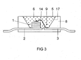
- the construction of a light source for white light is in FIG. 3 shown explicitly.
- the light source is a semiconductor device with a chip 1 of the type InGaN with a peak emission wavelength in the UV of, for example, 405 nm, up to 430 nm, which in an opaque base housing 8 is embedded in the region of a recess 9.
- the chip 1 is connected via a bonding wire 14 to a first terminal 3 and directly to a second electrical terminal 2.
- the recess 9 is filled with a potting compound 5 which contains as main constituents an epoxy casting resin (80 to 90% by weight) and phosphor pigments 6 (less than 20% by weight).
- the recess has a wall 17, which serves as a reflector for the primary and secondary radiation from the chip 1 and the pigments 6.
- the primary radiation of the UV LED is completely converted from the phosphor to green.
- the phosphor used is the oxynitridosilicate described above.
- FIG. 5 shows the spectral distribution of the emission of a luminescence conversion LED based on a UV primary emitting LED with peak at 405 nm.
Landscapes
- Chemical & Material Sciences (AREA)
- Inorganic Chemistry (AREA)
- Engineering & Computer Science (AREA)
- Materials Engineering (AREA)
- Organic Chemistry (AREA)
- Luminescent Compositions (AREA)
Description
- Diese Anmeldung steht in engem Zusammenhang mit folgenden Anmeldungen:
- 2003P14657, 2003P14656, und 2003P14655.
- Die Erfindung geht aus von einer grün emittierenden LED. Unter grün emittierend wird hier insbesondere eine Emission im Bereich um 560 m verstanden.
- Üblicherweise wird eine farbig emittierende LED durch einen entsprechend angepassten Chip realisiert. Im Falle einer grünen Emission ist dies jedoch problematisch, da etablierte Techniken wie ein InGaN-Chip (blau) oder ein InGaAlP-Chip (rot) wegen mangelnder Effizienz nicht eingesetzt werden können. Stattdessen müssen Sonderlösungen verwendet werden. Beispiele für derartige Sonderlösungen sind in
EP 584 599 DE 198 06 536 undDE 100 24 924 zu finden. Sie weisen jedoch immer noch eine relativ geringe Effizienz auf. Außerdem zeigen sie eine relativ starke Temperaturdrift des Farborts der Emission. - Als Alternative sind daher grün emittierende LEDs auf Basis von Lumineszenzkonversions-LEDs entwickelt worden. Beispiele finden sich in
WO 01/89001 EP 1 150 361 . Aber bis jetzt ist dabei keine höhere Effizienz erzielt worden als bei direkt emittierenden LEDs. Dies liegt an den bisher dafür zur Verfügung stehenden Leuchtstoffen (BAM-Derivate und Sulfide) und deren Anregbarkeit. - Leuchtstoffe des Typs Oxinitridosilikat sind an sich unter der Kurzformel MSiON bekannt; siehe beispielsweise "On new rare-earth doped M-Si-Al-O-N materials" , J. van Krevel, TU Eindhoven 2000, ISBN 90-386-2711-4, Kap. 6. sie sind mit Tb dotiert. Emission wir erreicht bei Anregung durch 365 nm oder 254 nm.
- Ein neuartiger Leuchtstoff ist aus der
EP-PA 02 021 172.8 EP-A 1 413 618 ) bekannt. Er besteht aus Eu- oder Eu,Mn-koaktiviertem Oxinitridosilikat der Formel MSi2O2N2 (M = Ca, Sr, Ba). Ein ähnlicher Leuchtstoff ist aus derEP-A 1 411 558 bekannt (jeweils Art. 54 (3)). - Es ist Aufgabe der vorliegenden Erfindung, eine grün emittierende LED gemäß dem Oberbegriff des Anspruchs 1 bereitzustellen, deren Effizienz möglichst hoch ist. Eine weitere Aufgabe ist die Stabilisierung des Farborts.
- Diese Aufgabe wird durch die kennzeichnenden Merkmale des Anspruchs 1 gelöst. Besonders vorteilhafte Ausgestaltungen finden sich in den abhängigen Ansprüchen.
- Bisher gibt es keinen grün emittierenden Leuchtstoff hoher Effizienz, der gleichzeitig unempfindlich gegen äußere Einflüsse ist und in einer LED nutzbar wäre.
- Erfindungsgemäß wird ein Leuchtstoff vorgeschlagen, der ein Oxinitridosilikat der Formel MSi2O2N2 (M = Ca, Sr, Ba) darstellt, das mit zweiwertigem Eu aktiviert ist, unter evtl. weiterer Zugabe von Mn als Koaktivator, wobei der Leuchtstoff überwiegend oder allein, also mit einem Anteil von mehr als 50 % des Leuchtstoffs, aus der HT-Phase besteht. Diese HT-Modifikation zeichnet sich dadurch aus, dass sie breitbandig anregbar aus, nämlich in einem weiten Bereich von 200 bis 480 nm, dass sie eine extrem hohe Stabilität gegen äußere Einflüsse besitzt, also bei 150°C keine messbare Degradation zeigt, und dass sie eine extrem gute Farbortstabilität unter wechselnden Bedingungen zeigt (zwischen 20 und 100 °C nur geringe Drift nachweisbar). Dieser Leuchtstoff wird im folgenden oft Sr-Sion:Eu genannt.
- Bei der Herstellung des neuartigen Leuchtstoffs kommt es vor allem auf eine hohe Temperatur an, der Synthesebereich liegt bei 1300 bis 1600 °C. Ein anderer bestimmender Faktor ist die Reaktivität der Ausgangskomponenten. Diese sollte möglichst hoch sein.
- Insbesondere kann dieser Leuchtstoff von einer LED, vor allem vom Typ InGaN, effizient angeregt werden.
- Der aus
EP-PA 02 021 172.8 - Überraschenderweise hat sich nun gezeigt, dass sich die beiden Phasen in ihrer Eignung als Leuchtstoff grundlegend unterscheiden. Während die NT-Phase als Eudotierter Leuchtstoff nur bedingt zu gebrauchen ist, und eher orange-rot emittiert, zeigt die HT-Phase eine hervorragende Eignung als Leuchtstoff, der grün emittiert. Häufig liegt eine Mischung beider Modifikationen vor, die breitbandig beide Emissionen erkennen lässt. Gewünscht ist daher, die HT-Phase möglichst rein, mit mindestens 50 % Anteil, bevorzugt mindestens 70 %, besonders bevorzugt mindestens 85% Anteil herzustellen.
- Dafür ist ein Glühprozess erforderlich, der bei mindestens 1300 °C, aber nicht mehr als 1600 °C durchgeführt wird. Bevorzugt ist ein Temperaturbereich von etwa 1450 bis 1580 °C, da bei geringerer Temperatur zunehmend NT-Phase entsteht und bei höherer Temperatur der Leuchtstoff zunehmend schlechter verarbeitbar ist, und ab etwa 1600 °C als hart gesinterte Keramik oder Schmelze vorliegt. Der optimale Temperaturbereich hängt von der genauen Zusammensetzung und den Eigenschaften der Ausgangsmaterialien ab.
- Besonders wichtig für das Herstellen eines effizienten Leuchtstoffs des Typs Sr-Sion ist ein Ansatz der Ausgangsprodukte, der im wesentlichen stöchiometrisch ist unter Verwendung der Grundkomponenten SiO 2, SrCO 3 sowie Si 3 N 4. Sr steht hier beispielhaft stellvertretend für M. Die Abweichung sollte insbesondere 10 %, bevorzugt 5 %, des idealen stöchiometrischen Ansatzes nicht überschreiten, wobei auch die etwaige Zugabe eines Schmelzmittels, wie es oft üblich ist, dabei eingeschlossen ist. Besonders bevorzugt ist eine maximale Abweichung von 1 %. Hinzu kommt ein Vorläufer für den Europium-Beitrag der Dotierung, der beispielsweise als Oxid Eu 2 O 3 realisiert wird. Diese Erkenntnis steht im Gegensatz zu der bisherigen Vorgehensweise, die Grundkomponente SiO 2 deutlich unterstöchiometrisch zuzugeben. Besonders überraschend ist diese Erkenntnis auch deswegen, weil andere als Leuchtstoff empfohlene Sione wie Ba-Sion gemäß der Lehre von
EP-PA 02 021 117.8 - Ein entsprechender Ansatz für das Sr-Sion MSi2O2N2 verwendet daher 11 bis 13 Gew.-% SiO 2, 27 bis 29 Gew.-% Si 3 N 4, Rest SrCO 3. Ba- und Ca- Anteile an M werden entsprechend als Carbonat zugesetzt. Europium wird entsprechend der gewünschten Dotierung, beispielsweise als Oxid oder Fluorid, als Ersatz für SrCO3 zugesetzt. Der Ansatz MSi2O2N2 meint dabei auch etwaige Abweichungen von der exakten Stöchiometrie, soweit sie hinsichtlich der Ladungserhaltung ausgeglichen sind.
- Als besonders günstig hat sich erwiesen, dass die Ausgangskomponenten des Wirtsgitters, insbesondere Si 3 N 4, möglichst hohe Reinheit besitzen. Besonders bevorzugt ist daher Si 3 N 4, das aus der flüssigen Phase, ausgehend beispielsweise von Siliziumtetrachlorid, synthetisiert ist. Als kritisch hat sich insbesondere die Verunreinigung mit Wolfram und Kobalt, erwiesen. Hier sollte die Verunreinigung möglichst gering sein, insbesondere sollte sie jeweils kleiner 100 ppm, insbesondere kleiner 50 ppm, sein, bezogen auf diese Vorläufersubstanzen. Des weiteren ist eine möglichst hohe Reaktivität vorteilhaft, sie lässt sich durch die reaktive Oberfläche (BET) quantifizieren. Diese sollte mindestens 6 m2/g betragen, vorteilhaft mindestens 8 m2/g. Auch die Verunreinigung an Aluminium und Calcium, bezogen auf diese Vorläufersubstanz Si 3 N 4, sollte möglichst unter 100 ppm liegen.
- Bei Abweichung von der oben angegebenen Verfahrensführung in bezug auf stöchiometrischen Ansatz und Temperaturführung entstehen als unerwünschte Fremdphasen in zunehmendem Maße Nitridosilikate MxSiyNz wie etwa M2Si5N8, wenn die SiO2-Zugabe zu niedrig angesetzt wird, so dass ein Stickstoffüberschuss entsteht. Obwohl diese Verbindung an sich ein bemerkenswerter Leuchtstoff ist, ist sie in Zusammenhang mit der Synthese des Sr-Sions genauso wie andere Nitridosilikate äußerst störend, weil diese Fremdphasen die grüne Strahlung des Sr-Sions absorbieren und evtl. in die bekannte rote Strahlung der Nitridosilikate umwandeln. Umgekehrt entstehen bei zu hoher SiO 2-Zugabe Sr-Silikate wie beispielsweise Sr2SiO4 weil ein Sauerstoffüberschuss entsteht. Beide Fremdphasen absorbieren die nutzbare grüne Emission oder führen zumindest zu Gitterdefekten wie Leerstellen, die die Effizienz des Leuchtstoffs stark beeinträchtigen. Als Anhaltspunkt dient die Richtschnur, dass der Anteil der Fremdphasen möglichst unter 15 %, bevorzugt sogar unter 5 %, liegen soll. Dies korrespondiert im XRD-Spektrum des synthetisierten Leuchtstoffs mit der Forderung, dass beim XRD-Ablenkwinkel 2 Θ im Bereich 25 bis 32° die Intensität aller Fremdphasenpeaks kleiner als 1/3, bevorzugt kleiner als ¼, besonders bevorzugt kleiner als 1/5, der Intensität des die HT-Modifikation kennzeichnenden Hauptpeaks bei etwa 31,8° sein soll. Dies gilt vor allem für die Fremdphasen vom Typ SrxSiyNz, insbesondere Sr2Si5N8.
- Im Falle einer optimierten Verfahrensführung lässt sich zuverlässig eine Quanteneffizienz von 80 bis deutlich über 90 % erzielen. Dagegen wird bei unspezifischer Verfahrensführung die Effizienz typisch im Bereich von höchstens 50 bis 60 % Quanteneffizienz liegen.
- Erfindungsgemäß lässt sich somit ein Leuchtstoff herstellen, der ein Oxinitridosilikat der Formel MSi2O2N2 (M = Ca, Sr, Ba) darstellt, das mit zweiwertigem Eu aktiviert ist, unter evtl. weiterer Zugabe von Mn als Koaktivator, wobei der Leuchtstoff überwiegend oder allein, also zu mehr als 50 % des Leuchtstoffs, bevorzugt zu mehr als 85% des Leuchtstoffs, aus der HT-Phase besteht. Diese HT-Modifikation zeichnet sich dadurch aus, dass sie breitbandig anregbar ist, nämlich in einem weiten Bereich von 50 bis 480 nm, insbesondere 150 bis 480 nm, besonders bevorzugt von 250 bis 470 nm, dass er eine extrem hohe Stabilität gegen äußere Einflüsse besitzt, also bei 150°C an Luft keine messbare Degradation zeigt, und dass er eine extrem gute Farbortstabilität unter wechselnden Bedingungen zeigt. Weitere Pluspunkte sind seine geringe Absorption im Roten, was besonders bei Leuchtstoffmischungen vorteilhaft ist. Dieser Leuchtstoff wird im folgenden oft Sr-Sion:Eu genannt. Ein Überwiegen der HT-Modifikation ist u.a. daran erkennbar, dass der kennzeichnende Peak der NT-Modifikation im XRD-Spektrum bei etwa 28,2 ° eine Intensität von weniger als 1:1, bevorzugt weniger als 1:2, im Vergleich zum Peak mit höchster Intensität aus der Dreiergruppe der Reflexe der HT-Modifikation, die im XRD-Spektrum bei 25 bis 27° liegen, aufweist. Die hier aufgeführten XRD-Spektren beziehen sich jeweils auf eine Anregung durch die bekannte Cu-Kα Linie.
- Bei gleicher Aktivatorkonzentration zeigt dieser Leuchtstoff ein anderes Emissionsverhalten als die NT-Variante gleicher Stöchiometrie. Die Halbwertsbreite der HT-Variante ist im Falle der optimierten HT-Variante wesentlich geringer als bei der einfachen fremdphasen- und defekthaltigen Mischung und liegt im Bereich 70 bis 80 nm, während die einfache Fremdphasen- bzw. defekthaltige Mischung eine Halbwertsbreite von etwa 110 bis 120 nm zeigt. Die dominante Wellenlänge ist bei der HT-Modifikation generell kürzer, typisch 10 bis 20 nm kürzer, als bei einer deutlich fremdphasenhaltigen Probe. Hinzu kommt, dass die Effizienz der hochreinen HT Modifikation typisch um mindestens 20 % höher, teilweise deutlich noch höher, als bei der NT-dominierten oder hoch fremdphasenhaltigen Mischung liegt.
- Ein kennzeichnendes Merkmal eines ausreichend geringen Anteils der NT-Modifikation und Fremdphasen ist eine Halbwertsbreite (FWHM) der Emission von weniger als 90 nm. Denn je geringer der Anteil an Fremdphasen, desto geringer ist der Anteil der spezifischen orange-roten Emission der fremdphasenreichen Modifikation, insbesondere der Nitridosilikat-Fremdphasen Sr-Si-N-Eu wie vor allem Sr2Si5N8:Eu.
- Hilfreich zur Charakterisierung sind neben der verringerten Halbwertsbreite die oben angegebenen typischen Reflexe im XRD-Spekrum, die die andere Kristallstruktur verdeutlichen.
- Der vorherrschende Peak im XRD-Spektrum der HT-Modifikation ist der Peak bei etwa 31.7°. weitere prominente Peaks sind die drei Peaks etwa gleicher Intensität zwischen 25 und 27° (25,3 und 26,0 und 26,3°), wobei der Peak mit kleinster Ablenkung der intensivste ist. ein weiterer intensiver Peak ist 12,6°.
- Dieser Leuchtstoff ist vor allem grün emittierend mit einer Dominanzwellenlänge im Bereich 555 bis 565 nm.
- Auch eine geringfügige Beimengung der Gruppe AlO als Ersatz der Gruppe SiN im Molekül des Oxinitridosilikats der Formel MSi2O2N2 ist möglich, insbesondere bis maximal 30 % des SiN-Anteils.
- Beide Phasen des Sr-Sion:Eu können analog zu den zwei strukturell unterschiedlichen Wirtsgittermodifikationen kristallisieren und jeweils über die Ansatzstöchiometrie SrSi2O2N2:Eu hergestellt werden. Geringe Abweichungen von dieser Stöchiometrie sind möglich. Die mit Eu dotierten Wirtsgitter lumineszieren überraschenderweise beide bei Anregung im Blauen oder UV, allerdings je nach Wirtsgittermodifikation mit anderer Emissionsfarbe. Die NT-Modifikation zeigt eine orangefarbene Emission, die HT-Modifikation eine grüne Emission bei etwa λdom = 560 nm mit prinzipiell deutlich höherer Effizienz. Je nach Dotiergehalt und Dotiermaterial (Eu oder Eu, Mn) sowie den relativen Anteilen der HT- und NT-Modifikation lässt sich eine gewünschte Eigenschaft des Leuchtstoffs genau einstellen.
- Ein Vorzug der HT-Phase ist die über einen sehr weiten Spektralbereich gleichmäßig gute Anregbarkeit bei nur wenig variierender Quanteneffizienz.
- Außerdem hängt die Lumineszenz der HT-Modifikation in einem weiten Temperaturbereich nur schwach von der Temperatur ab. Damit ist erstmals ein grün emittierender Leuchtstoff, bevorzugt für LED-Anwendungen, gefunden, der ohne besondere Maßnahmen zur Stabilisierung auskommt. Dies zeichnet ihn besonders gegen die bisher als aussichtsreichste Kandidaten angesehenen Leuchtstoffe für diese Aufgabe aus, nämlich Thiogallat-Leuchtstoffe oder Chlorosilikate.
- Die Sionverbindungen mit M = (Sr,Ba), bevorzugt ohne Ba oder mit Ba-Anteil bis zu 10 %, stellen effiziente Leuchtstoffe mit einem weiten Bereich der Emissionsmaxima dar. Diese liegen meist kurzwelliger als bei reinem Sr-Sion, bevorzugt zwischen 520 und 565 nm. Der erreichbare Farbraum lässt sich außerdem durch geringe Beigaben (bevorzugt bis 30 mol-%) an Ca und/oder Zink erweitern; dadurch werden die Emissionsmaxima eher in den langwelligeren Bereich, verglichen mit reinem Sr-Sion, verschoben, sowie durch partiellen Ersatz (bis 25 mol-%) von Si durch Ge und/oder Sn.
- Eine weitere Ausführungsform ist die Teilsubstitution von M, insbesondere Sr, durch drei- oder einwertige Ionen wie La3+ oder Li+. Bevorzugt ist ein Anteil dieser Ionen von maximal 20 mol-% des M.
- Überraschend ist nun mit dem Sr-Sion der HT-Phase ein Leuchtstoff gefunden, der sich exakt auf eine Emission der Wellenlänge λdom = 560 nm (Dominanzwellenlänge) einstellen lässt. Der Leuchtstoff wandelt das Licht einer blauen oder UV-LED mit einer Quanteneffizienz von deutlich mehr als 80 % um. Die lumenbewertete Effizienz ist vergleichbar mit der typischer weißer LEDs auf YAG:Ce-Basis. Damit ist eine "pure green" Konversions-LED fast eine Größenordnung effizienter als die reine Halbleitervariante.
- Als weiterer Vorteil ist anzusehen, dass die Emissionsfarbe der Lumineszenzkonversions-LED praktisch unabhängig von der Betriebstemperatur ist, damit kann die LED gut bei unterschiedlichen Außentemperaturen betriebe werden und ist farbortstabil dimmbar.
- Die Erfindung betrifft weiterhin ein Beleuchtungssystem mit LEDs wie oben beschrieben, wobei das Beleuchtungssystem weiterhin elektronische Komponenten enthält. diese vermitteln beispielsweise die Dimmbarkeit. Eine weitere Aufgabe der Elektronik ist die Ansteuerung einzelner LEDs oder auch Gruppen von LEDs. Diese Funktionen können durch vorbekannte elektronische Elemente realisiert sein.
- Im folgenden soll die Erfindung anhand zweier Ausführungsbeispiele näher erläutert werden. Es zeigen:
- Figur 1
- ein Emissionsspektrum eines ersten Oxinitridosilikats;
- Figur 2
- das Reflektionsspektrum dieses Nitridosilikats;
- Figur 3
- ein Halbleiterbauelement, das als Lichtquelle für grünes Licht als Lumineszenzkonversions-LED dient;
- Figur 4
- das Farbdiagramm mit einem nutzbaren Bereich für reines Grün. als Viereck eingezeichnet.
- Figur 5
- zeigt die spektrale Verteilung der Lumineszenzkonversions-LED.
- Ein konkretes Beispiel für den erfindungsgemäßen Leuchtstoff ist in
Figur 1 gezeigt. Es handelt sich um die Emission des Leuchtstoffs SrSi2N2O2:(5 % Eu2+) in HT-Modifikation, bei dem der Eu-Anteil 5 mol-% der von Sr besetzten Gitterplätze ausmacht. Das Emissionsmaximum liegt bei 540 nm, die mittlere Wellenlänge λdom bei 558 nm. Der Farbort ist x=0,357; y=0,605. Die Anregung erfolgte hier bei 460 nm. die FWHM ist 76 nm. Die Quanteneffizienz liegt bei etwa 90 %. Der Farbort ist x = 0,357, y = 0,605. -
Figur 2 zeigt das diffuse Reflexionsspektrum dieses Leuchtstoffs. Es zeigt ein ausgeprägtes Minimum im Bereich unter 440 nm, das somit die gute Anregbarkeit in diesem Bereich demonstriert. - Der Aufbau einer Lichtquelle für weißes Licht ist in
Figur 3 explizit gezeigt. Die Lichtquelle ist ein Halbleiterbauelement mit einem Chip 1 des Typs InGaN mit einer Peakemissionswellenlänge im UV von beispielsweise 405 nm, bis zu 430 nm, das in ein lichtundurchlässiges Grundgehäuse 8 im Bereich einerAusnehmung 9 eingebettet ist. Der Chip 1 ist über einen Bonddraht 14 mit einem ersten Anschluss 3 und direkt mit einem zweiten elektrischen Anschluss 2 verbunden. Die Ausnehmung 9 ist mit einer Vergussmasse 5 gefüllt, die als Hauptbestandteile ein Epoxidgießharz (80 bis 90 Gew.-%) und Leuchtstoffpigmente 6 (weniger als 20 Gew.-%) enthält. Die Ausnehmung hat eine Wand 17, die als Reflektor für die Primär- und Sekundärstrahlung vom Chip 1 bzw. den Pigmenten 6 dient. Die Primärstrahlung der UV-LED wird vollständig vom Leuchtstoff in grün konvertiert. Der verwendete Leuchtstoff ist das oben beschriebene Oxinitridosilikat. - Als nutzbarer reingrüner Bereich ("pure green"), der hier angestrebt ist, wird ein Bereich angesehen der im Farbdiagramm in etwa durch ein Viereck mit den Ecken
- (1): x/y = 0,22/0,595;
- (2): x/y = 0,37/0,46;
- (3): x/y = 0,41/0,59 und
- (4): x/y = 0,225/0,755
-
Figur 5 zeigt die spektrale Verteilung der Emission einer Lumineszenzkonversions-LED auf Basis einer UV-primär emittierenden LED mit Peak bei 405 nm.
Claims (10)
- Grün emittierende LED, die als Lumineszenzkonversions-LED ausgeführt ist, bestehend aus einer Primär-Strahlungsquelle, die ein Chip ist, der im UV oder blauen Strahlungsbereich emittiert, und einer davor angeordneten Schicht eines Leuchtstoffs, die die Strahlung des Chip teilweise oder vollständig in grünes Licht der dominanten Wellenlänge λdom = 550 bis 570 nm konvertiert, dadurch gekennzeichnet, dass der Leuchtstoff der Klasse der Oxinitridosilikate angehört, mit einem Kation M und der grundsätzlichen Formel M(1-c)Si2O2N2:Dc, wobei D eine Dotierung mit zweiwertigem Europium bedeutet und wobei der Anteil c der Dotierung am Kation im Bereich 0,1 bis 20 Mol. -% liegt, und wobei M als Bestandteil Sr umfasst und M = Sr allein oder M = Sr(1-x-y)BayCax mit 0 ≤ x+y < 0,5 verwendet wird, und wobei das Oxinitridosilikat vollständig oder überwiegend aus der hochtemperaturstabilen Modifikation HT besteht, wobei der Anteil der Verunreinigung an Wolfram und Kobalt jeweils unter 50 ppm liegt .
- LED nach Anspruch 1, dadurch gekennzeichnet, dass Sr als M den überwiegenden Anteil stellt und ein Teil von M, insbesondere bis zu 30 mol-%, durch Ba und/oder Ca ersetzt ist.
- LED nach Anspruch 1, dadurch gekennzeichnet, dass ein Teil von M, insbesondere bis zu 30 mol-%, durch Li und/oder La und/oder Zn ersetzt ist.
- LED nach Anspruch 1, dadurch gekennzeichnet, dass ein Teil der Gruppe SiN im Oxinitridosilikat der Formel MSi2O2N2, insbesondere bis zu 30 mol-%, durch die Gruppe AlO ersetzt ist.
- LED nach Anspruch 1, dadurch gekennzeichnet, dass ein Teil von Eu, insbesondere bis zu 30 mol-%, durch Mn ersetzt ist.
- LED nach Anspruch 1, dadurch gekennzeichnet, dass die primäre Emission eine Peakwellenlänge im Bereich 340 bis 430 nm, insbesondere mindestens 380 nm, hat.
- LED nach Anspruch 1, dadurch gekennzeichnet, dass die grüne Emission eine dominante Wellenlänge im Bereich 556 bis 564 nm hat.
- LED nach Anspruch 1, dadurch gekennzeichnet, dass die primäre Strahlung vollständig konvertiert wird.
- LED nach Anspruch 1, dadurch gekennzeichnet, dass der Chip ein InGaN-Chip mit einer Peakemissionswellenlänge im Bereich von 430 bis 465 nm ist.
- LED nach Anspruch 1, dadurch gekennzeichnet, dass die LED dimmbar ist.
Priority Applications (1)
| Application Number | Priority Date | Filing Date | Title |
|---|---|---|---|
| EP10190226A EP2275512B1 (de) | 2003-09-24 | 2004-09-24 | Grün emittierende LED |
Applications Claiming Priority (2)
| Application Number | Priority Date | Filing Date | Title |
|---|---|---|---|
| DE10344376 | 2003-09-24 | ||
| PCT/DE2004/002136 WO2005030904A1 (de) | 2003-09-24 | 2004-09-24 | Grün emittierende led |
Related Child Applications (1)
| Application Number | Title | Priority Date | Filing Date |
|---|---|---|---|
| EP10190226A Division-Into EP2275512B1 (de) | 2003-09-24 | 2004-09-24 | Grün emittierende LED |
Publications (2)
| Publication Number | Publication Date |
|---|---|
| EP1664238A1 EP1664238A1 (de) | 2006-06-07 |
| EP1664238B1 true EP1664238B1 (de) | 2015-11-18 |
Family
ID=34384263
Family Applications (2)
| Application Number | Title | Priority Date | Filing Date |
|---|---|---|---|
| EP10190226A Expired - Lifetime EP2275512B1 (de) | 2003-09-24 | 2004-09-24 | Grün emittierende LED |
| EP04786852.6A Expired - Lifetime EP1664238B1 (de) | 2003-09-24 | 2004-09-24 | Grün emittierende led |
Family Applications Before (1)
| Application Number | Title | Priority Date | Filing Date |
|---|---|---|---|
| EP10190226A Expired - Lifetime EP2275512B1 (de) | 2003-09-24 | 2004-09-24 | Grün emittierende LED |
Country Status (7)
| Country | Link |
|---|---|
| US (1) | US7851988B2 (de) |
| EP (2) | EP2275512B1 (de) |
| JP (1) | JP4805828B2 (de) |
| KR (1) | KR101130029B1 (de) |
| CN (1) | CN1856561B (de) |
| TW (1) | TWI356503B (de) |
| WO (1) | WO2005030904A1 (de) |
Families Citing this family (19)
| Publication number | Priority date | Publication date | Assignee | Title |
|---|---|---|---|---|
| TW200523340A (en) * | 2003-09-24 | 2005-07-16 | Patent Treuhand Ges Fur Elek Sche Gluhlampen Mbh | Hochefeizienter leuchtstoff |
| DE102004051395A1 (de) * | 2004-10-21 | 2006-04-27 | Patent-Treuhand-Gesellschaft für elektrische Glühlampen mbH | Hocheffizienter stabiler Oxinitrid-Leuchtstoff |
| DE102005030761A1 (de) * | 2005-07-01 | 2007-01-04 | Carl Zeiss Jena Gmbh | Beleuchtungseinrichtung für Mikroskope |
| DE102005059521A1 (de) | 2005-12-13 | 2007-06-14 | Patent-Treuhand-Gesellschaft für elektrische Glühlampen mbH | Rot emittierender Leuchtstoff und Lichtquelle mit einem derartigen Leuchtstoff |
| US7857994B2 (en) | 2007-05-30 | 2010-12-28 | GE Lighting Solutions, LLC | Green emitting phosphors and blends thereof |
| CN101157854B (zh) * | 2007-07-02 | 2010-10-13 | 北京宇极科技发展有限公司 | 一种氮氧化合物发光材料、其制备方法及其应用 |
| CN101765925B (zh) * | 2007-07-30 | 2012-06-13 | 夏普株式会社 | 发光装置、照明装置及具有照明装置的无尘室 |
| WO2009017206A1 (ja) * | 2007-08-01 | 2009-02-05 | Mitsubishi Chemical Corporation | 蛍光体及びその製造方法、結晶性窒化珪素及びその製造方法、蛍光体含有組成物、並びに、該蛍光体を用いた発光装置、画像表示装置及び照明装置 |
| RU2010127293A (ru) * | 2007-12-03 | 2012-01-10 | Конинклейке Филипс Электроникс Н.В. (Nl) | Светоизлучающее устройство, содержащее материал зеленого свечения на основе sialon (сиалона) |
| US8957435B2 (en) * | 2009-04-28 | 2015-02-17 | Cree, Inc. | Lighting device |
| CN101775292A (zh) * | 2010-02-23 | 2010-07-14 | 厦门大学 | 一种Eu掺杂氮氧化物荧光粉的制备方法 |
| CN101818063B (zh) * | 2010-05-14 | 2013-03-06 | 中国科学技术大学 | 制备硅基氧氮化物荧光粉的方法 |
| CN102344797A (zh) * | 2010-07-29 | 2012-02-08 | 福华电子股份有限公司 | 一种荧光粉组成物及使用该荧光粉的交流电发光二极管 |
| KR101890185B1 (ko) * | 2012-01-27 | 2018-08-21 | 엘지이노텍 주식회사 | 형광체 및 발광 장치 |
| CN102618261A (zh) * | 2012-03-09 | 2012-08-01 | 东华大学 | 一种CaSi2O2N2:Eu2+, Dy3+, Li+荧光粉及其制备方法 |
| KR102235612B1 (ko) | 2015-01-29 | 2021-04-02 | 삼성전자주식회사 | 일-함수 금속을 갖는 반도체 소자 및 그 형성 방법 |
| WO2016198348A1 (en) | 2015-06-12 | 2016-12-15 | Philips Lighting Holding B.V. | Ac-led with hybrid led channels |
| CN105838371A (zh) * | 2016-04-27 | 2016-08-10 | 山东盈光新材料有限公司 | 一种led用氮氧化物荧光粉及制备方法 |
| DE102018212724A1 (de) | 2018-07-31 | 2020-02-06 | Osram Opto Semiconductors Gmbh | Grüner leuchtstoff und beleuchtungsvorrichtung |
Family Cites Families (23)
| Publication number | Priority date | Publication date | Assignee | Title |
|---|---|---|---|---|
| DE59308636D1 (de) | 1992-08-28 | 1998-07-09 | Siemens Ag | Leuchtdiode |
| US5374415A (en) * | 1993-02-03 | 1994-12-20 | General Motors Corporation | Method for forming carbon fibers |
| JP3356041B2 (ja) | 1997-02-17 | 2002-12-09 | 昭和電工株式会社 | リン化ガリウム緑色発光素子 |
| US6255670B1 (en) * | 1998-02-06 | 2001-07-03 | General Electric Company | Phosphors for light generation from light emitting semiconductors |
| US6603258B1 (en) | 2000-04-24 | 2003-08-05 | Lumileds Lighting, U.S. Llc | Light emitting diode device that emits white light |
| US6621211B1 (en) | 2000-05-15 | 2003-09-16 | General Electric Company | White light emitting phosphor blends for LED devices |
| DE10024924A1 (de) | 2000-05-19 | 2001-11-29 | Osram Opto Semiconductors Gmbh | Licht emittierendes Halbleiterbauelement |
| JP2004505172A (ja) * | 2000-07-28 | 2004-02-19 | オスラム オプト セミコンダクターズ ゲゼルシャフト ミット ベシュレンクテル ハフツング | 波長変換のためのルミネセンス変換ベースの発光ダイオード及び蛍光体 |
| JP2002076434A (ja) * | 2000-08-28 | 2002-03-15 | Toyoda Gosei Co Ltd | 発光装置 |
| US6632379B2 (en) * | 2001-06-07 | 2003-10-14 | National Institute For Materials Science | Oxynitride phosphor activated by a rare earth element, and sialon type phosphor |
| DE10147040A1 (de) * | 2001-09-25 | 2003-04-24 | Patent Treuhand Ges Fuer Elektrische Gluehlampen Mbh | Beleuchtungseinheit mit mindestens einer LED als Lichtquelle |
| CA2473825A1 (en) * | 2002-07-11 | 2004-01-22 | Sumitomo Electric Industries, Ltd. | Porous semiconductor and process for producing the same |
| EP1413618A1 (de) * | 2002-09-24 | 2004-04-28 | Osram Opto Semiconductors GmbH | Lumineszentes Material, insbesondere zur Anwendung in Leuchtdioden |
| US6717353B1 (en) * | 2002-10-14 | 2004-04-06 | Lumileds Lighting U.S., Llc | Phosphor converted light emitting device |
| DE60305958T2 (de) * | 2002-10-14 | 2007-01-25 | Philips Intellectual Property & Standards Gmbh | Lichtemittierendes bauelement mit einem eu(ii)-aktivierten leuchtstoff |
| US7074346B2 (en) * | 2003-02-06 | 2006-07-11 | Ube Industries, Ltd. | Sialon-based oxynitride phosphor, process for its production, and use thereof |
| DE112004001533B4 (de) * | 2003-08-22 | 2021-07-22 | National Institute For Materials Science | Leuchtbauelement und Bildanzeige enthaltend ein fluoreszierendes Oxynitridmaterial |
| US7723740B2 (en) * | 2003-09-18 | 2010-05-25 | Nichia Corporation | Light emitting device |
| TW200523340A (en) * | 2003-09-24 | 2005-07-16 | Patent Treuhand Ges Fur Elek Sche Gluhlampen Mbh | Hochefeizienter leuchtstoff |
| CN1886483B (zh) * | 2003-09-24 | 2010-06-16 | 电灯专利信托有限公司 | 具有改进颜色重现性的基于发光二极管的高效照明系统 |
| TWI359187B (en) * | 2003-11-19 | 2012-03-01 | Panasonic Corp | Method for preparing nitridosilicate-based compoun |
| JP4524468B2 (ja) * | 2004-05-14 | 2010-08-18 | Dowaエレクトロニクス株式会社 | 蛍光体とその製造方法および当該蛍光体を用いた光源並びにled |
| JP4888624B2 (ja) * | 2004-07-30 | 2012-02-29 | 独立行政法人物質・材料研究機構 | α型サイアロン粉末の製造方法 |
-
2004
- 2004-09-24 CN CN2004800275916A patent/CN1856561B/zh not_active Expired - Lifetime
- 2004-09-24 EP EP10190226A patent/EP2275512B1/de not_active Expired - Lifetime
- 2004-09-24 EP EP04786852.6A patent/EP1664238B1/de not_active Expired - Lifetime
- 2004-09-24 TW TW093128945A patent/TWI356503B/zh not_active IP Right Cessation
- 2004-09-24 JP JP2006527271A patent/JP4805828B2/ja not_active Expired - Lifetime
- 2004-09-24 KR KR1020067007848A patent/KR101130029B1/ko not_active Expired - Lifetime
- 2004-09-24 WO PCT/DE2004/002136 patent/WO2005030904A1/de not_active Ceased
- 2004-09-24 US US10/572,891 patent/US7851988B2/en active Active
Also Published As
| Publication number | Publication date |
|---|---|
| EP2275512A2 (de) | 2011-01-19 |
| TWI356503B (en) | 2012-01-11 |
| JP4805828B2 (ja) | 2011-11-02 |
| CN1856561A (zh) | 2006-11-01 |
| TW200516789A (en) | 2005-05-16 |
| EP1664238A1 (de) | 2006-06-07 |
| KR101130029B1 (ko) | 2012-03-28 |
| JP2007507095A (ja) | 2007-03-22 |
| US20070034885A1 (en) | 2007-02-15 |
| CN1856561B (zh) | 2011-09-21 |
| EP2275512B1 (de) | 2012-07-25 |
| WO2005030904A1 (de) | 2005-04-07 |
| US7851988B2 (en) | 2010-12-14 |
| KR20060096442A (ko) | 2006-09-11 |
| EP2275512A3 (de) | 2011-09-28 |
Similar Documents
| Publication | Publication Date | Title |
|---|---|---|
| EP1664239B1 (de) | Weiss emittierende led mit definierter farbtemperatur | |
| EP1670875B1 (de) | Hocheffizientes beleuchtungssystem auf led-basis mit verbesserter farbwiedergabe | |
| EP1664238B1 (de) | Grün emittierende led | |
| DE102007035592B4 (de) | Temperaturstabiler Leuchtstoff, Verwendung eines Leuchtstoffs und Verfahren zur Herstellung eines Leuchtstoffs | |
| EP1670876B1 (de) | Hocheffizienter leuchtstoff | |
| EP2366755B1 (de) | Herstellverfahren für einen gelb emittierenden Leuchtstoff | |
| DE112007001638B4 (de) | Leuchtstoff aus der Klasse der Nitridosilikate, Verfahren zur Herstellung eines Leuchtstoff aus der Klasse der Nitridosilikate und Verwendung eines derartigen Leuchtstoffs in einer Lichtquelle | |
| DE60307415T2 (de) | Fotolumineszierende stoffe für leuchtdioden, und leuchtdiode | |
| DE102011115879A1 (de) | Optoelektronisches Bauelement und Leuchtstoffe | |
| EP2914688B1 (de) | Eu-aktivierte leuchtstoffe | |
| EP2841529B1 (de) | Silicat-leuchtstoffe | |
| DE102004038199A1 (de) | LED mit niedriger Farbtemperatur | |
| DE102005005263A1 (de) | Gelb emittierender Leuchtstoff und Lichtquelle mit derartigem Leuchtstoff | |
| DE102006016548B4 (de) | Blau bis Gelb-Orange emittierender Leuchtstoff und Lichtquelle mit derartigem Leuchtstoff | |
| EP1966345B1 (de) | Rot emittierender leuchtstoff und lichtquelle mit einem derartigen leuchtstoff | |
| EP2220191B1 (de) | Wellenlängenkonvertierte LED | |
| EP2217678B1 (de) | Leuchtstoff und beleuchtungssystem mit derartigem leuchtstoff | |
| EP2491095B1 (de) | Leuchtstoff und lichtquelle mit derartigem leuchtstoff | |
| DE102022126560A1 (de) | Konversionsstoff, stoffgemisch, verfahren zur herstellung eines konversionsstoffs und strahlungsemittierendes bauelement |
Legal Events
| Date | Code | Title | Description |
|---|---|---|---|
| PUAI | Public reference made under article 153(3) epc to a published international application that has entered the european phase |
Free format text: ORIGINAL CODE: 0009012 |
|
| 17P | Request for examination filed |
Effective date: 20060322 |
|
| AK | Designated contracting states |
Kind code of ref document: A1 Designated state(s): BE DE FR GB IT NL |
|
| DAX | Request for extension of the european patent (deleted) | ||
| RBV | Designated contracting states (corrected) |
Designated state(s): BE DE FR GB IT NL |
|
| RIN1 | Information on inventor provided before grant (corrected) |
Inventor name: BRUNNER, HERBERT Inventor name: BRAUNE, BERT Inventor name: JERMANN, FRANK Inventor name: FIEDLER, TIM Inventor name: ZACHAU, MARTIN |
|
| RIN1 | Information on inventor provided before grant (corrected) |
Inventor name: BRUNNER, HERBERT Inventor name: JERMANN, FRANK Inventor name: ZACHAU, MARTIN Inventor name: DIE ANDERE ERFINDER HABEN AUF IHRE NENNUNG VERZICH Inventor name: BRAUNE, BERT |
|
| RIN1 | Information on inventor provided before grant (corrected) |
Inventor name: BRAUNE, BERT Inventor name: JERMANN, FRANK Inventor name: FIEDLER, TIM Inventor name: BRUNNER, HERBERT Inventor name: ZACHAU, MARTIN |
|
| RAP1 | Party data changed (applicant data changed or rights of an application transferred) |
Owner name: OSRAM OPTO SEMICONDUCTORS GMBH Owner name: PATENT-TREUHAND-GESELLSCHAFT FUER ELEKTRISCHE GLUE |
|
| RAP1 | Party data changed (applicant data changed or rights of an application transferred) |
Owner name: PATENT-TREUHAND-GESELLSCHAFT FUER ELEKTRISCHE GLUE Owner name: OSRAM OPTO SEMICONDUCTORS GMBH |
|
| 17Q | First examination report despatched |
Effective date: 20081107 |
|
| RAP1 | Party data changed (applicant data changed or rights of an application transferred) |
Owner name: OSRAM GESELLSCHAFT MIT BESCHRAENKTER HAFTUNG Owner name: OSRAM OPTO SEMICONDUCTORS GMBH |
|
| RAP1 | Party data changed (applicant data changed or rights of an application transferred) |
Owner name: OSRAM OPTO SEMICONDUCTORS GMBH Owner name: OSRAM AG |
|
| RAP1 | Party data changed (applicant data changed or rights of an application transferred) |
Owner name: OSRAM OPTO SEMICONDUCTORS GMBH Owner name: OSRAM GMBH |
|
| RAP1 | Party data changed (applicant data changed or rights of an application transferred) |
Owner name: OSRAM GMBH Owner name: OSRAM OPTO SEMICONDUCTORS GMBH |
|
| GRAP | Despatch of communication of intention to grant a patent |
Free format text: ORIGINAL CODE: EPIDOSNIGR1 |
|
| INTG | Intention to grant announced |
Effective date: 20150709 |
|
| GRAS | Grant fee paid |
Free format text: ORIGINAL CODE: EPIDOSNIGR3 |
|
| GRAA | (expected) grant |
Free format text: ORIGINAL CODE: 0009210 |
|
| AK | Designated contracting states |
Kind code of ref document: B1 Designated state(s): BE DE FR GB IT NL |
|
| REG | Reference to a national code |
Ref country code: GB Ref legal event code: FG4D Free format text: NOT ENGLISH |
|
| REG | Reference to a national code |
Ref country code: DE Ref legal event code: R096 Ref document number: 502004015075 Country of ref document: DE |
|
| REG | Reference to a national code |
Ref country code: NL Ref legal event code: MP Effective date: 20160218 |
|
| PG25 | Lapsed in a contracting state [announced via postgrant information from national office to epo] |
Ref country code: IT Free format text: LAPSE BECAUSE OF FAILURE TO SUBMIT A TRANSLATION OF THE DESCRIPTION OR TO PAY THE FEE WITHIN THE PRESCRIBED TIME-LIMIT Effective date: 20151118 Ref country code: NL Free format text: LAPSE BECAUSE OF FAILURE TO SUBMIT A TRANSLATION OF THE DESCRIPTION OR TO PAY THE FEE WITHIN THE PRESCRIBED TIME-LIMIT Effective date: 20151118 |
|
| REG | Reference to a national code |
Ref country code: DE Ref legal event code: R097 Ref document number: 502004015075 Country of ref document: DE |
|
| PLBE | No opposition filed within time limit |
Free format text: ORIGINAL CODE: 0009261 |
|
| STAA | Information on the status of an ep patent application or granted ep patent |
Free format text: STATUS: NO OPPOSITION FILED WITHIN TIME LIMIT |
|
| 26N | No opposition filed |
Effective date: 20160819 |
|
| PG25 | Lapsed in a contracting state [announced via postgrant information from national office to epo] |
Ref country code: BE Free format text: LAPSE BECAUSE OF NON-PAYMENT OF DUE FEES Effective date: 20160930 |
|
| GBPC | Gb: european patent ceased through non-payment of renewal fee |
Effective date: 20160924 |
|
| REG | Reference to a national code |
Ref country code: FR Ref legal event code: ST Effective date: 20170531 |
|
| PG25 | Lapsed in a contracting state [announced via postgrant information from national office to epo] |
Ref country code: FR Free format text: LAPSE BECAUSE OF NON-PAYMENT OF DUE FEES Effective date: 20160930 Ref country code: GB Free format text: LAPSE BECAUSE OF NON-PAYMENT OF DUE FEES Effective date: 20160924 |
|
| REG | Reference to a national code |
Ref country code: BE Ref legal event code: MM Effective date: 20160930 |
|
| P01 | Opt-out of the competence of the unified patent court (upc) registered |
Effective date: 20230927 |
|
| PGFP | Annual fee paid to national office [announced via postgrant information from national office to epo] |
Ref country code: DE Payment date: 20230920 Year of fee payment: 20 |
|
| REG | Reference to a national code |
Ref country code: DE Ref legal event code: R071 Ref document number: 502004015075 Country of ref document: DE |