EP1665983A2 - Appareil de détermination de l'impédance du thorax - Google Patents
Appareil de détermination de l'impédance du thorax Download PDFInfo
- Publication number
- EP1665983A2 EP1665983A2 EP05024364A EP05024364A EP1665983A2 EP 1665983 A2 EP1665983 A2 EP 1665983A2 EP 05024364 A EP05024364 A EP 05024364A EP 05024364 A EP05024364 A EP 05024364A EP 1665983 A2 EP1665983 A2 EP 1665983A2
- Authority
- EP
- European Patent Office
- Prior art keywords
- voltage
- signal generator
- impedance
- value
- measurement
- Prior art date
- Legal status (The legal status is an assumption and is not a legal conclusion. Google has not performed a legal analysis and makes no representation as to the accuracy of the status listed.)
- Granted
Links
- 210000000038 chest Anatomy 0.000 title abstract 2
- 239000007943 implant Substances 0.000 claims abstract description 94
- 238000005259 measurement Methods 0.000 claims description 134
- 238000002847 impedance measurement Methods 0.000 claims description 41
- 238000012544 monitoring process Methods 0.000 claims description 33
- 230000002051 biphasic effect Effects 0.000 claims description 22
- 230000000747 cardiac effect Effects 0.000 claims description 15
- 230000007774 longterm Effects 0.000 claims description 13
- 230000005540 biological transmission Effects 0.000 claims description 8
- 230000000694 effects Effects 0.000 claims description 7
- 230000000241 respiratory effect Effects 0.000 claims description 7
- 241001465754 Metazoa Species 0.000 claims description 5
- 238000004891 communication Methods 0.000 claims description 5
- 230000003321 amplification Effects 0.000 claims description 3
- 238000003199 nucleic acid amplification method Methods 0.000 claims description 3
- 230000000977 initiatory effect Effects 0.000 claims 6
- 238000001514 detection method Methods 0.000 claims 1
- 210000001519 tissue Anatomy 0.000 description 57
- 210000004072 lung Anatomy 0.000 description 33
- 206010030113 Oedema Diseases 0.000 description 14
- 230000015572 biosynthetic process Effects 0.000 description 8
- 210000005003 heart tissue Anatomy 0.000 description 8
- 206010037423 Pulmonary oedema Diseases 0.000 description 7
- 238000000034 method Methods 0.000 description 7
- 208000005333 pulmonary edema Diseases 0.000 description 7
- 238000012935 Averaging Methods 0.000 description 6
- 230000002685 pulmonary effect Effects 0.000 description 6
- 230000008901 benefit Effects 0.000 description 5
- 230000001419 dependent effect Effects 0.000 description 5
- 238000002347 injection Methods 0.000 description 5
- 239000007924 injection Substances 0.000 description 5
- 230000006399 behavior Effects 0.000 description 4
- 230000029058 respiratory gaseous exchange Effects 0.000 description 4
- 239000003990 capacitor Substances 0.000 description 3
- 238000003745 diagnosis Methods 0.000 description 3
- 230000006870 function Effects 0.000 description 3
- 230000036541 health Effects 0.000 description 3
- 230000037390 scarring Effects 0.000 description 3
- 206010019280 Heart failures Diseases 0.000 description 2
- 238000011161 development Methods 0.000 description 2
- 238000010586 diagram Methods 0.000 description 2
- 239000012530 fluid Substances 0.000 description 2
- 230000010354 integration Effects 0.000 description 2
- 238000000691 measurement method Methods 0.000 description 2
- 230000000750 progressive effect Effects 0.000 description 2
- 230000009467 reduction Effects 0.000 description 2
- 238000002560 therapeutic procedure Methods 0.000 description 2
- 206010007558 Cardiac failure chronic Diseases 0.000 description 1
- 230000035508 accumulation Effects 0.000 description 1
- 238000009825 accumulation Methods 0.000 description 1
- 210000003484 anatomy Anatomy 0.000 description 1
- 239000008280 blood Substances 0.000 description 1
- 210000004369 blood Anatomy 0.000 description 1
- 210000004204 blood vessel Anatomy 0.000 description 1
- 210000001124 body fluid Anatomy 0.000 description 1
- 239000010839 body fluid Substances 0.000 description 1
- 230000008859 change Effects 0.000 description 1
- 238000006243 chemical reaction Methods 0.000 description 1
- 210000003109 clavicle Anatomy 0.000 description 1
- 230000008602 contraction Effects 0.000 description 1
- 230000001934 delay Effects 0.000 description 1
- 230000006866 deterioration Effects 0.000 description 1
- 230000003292 diminished effect Effects 0.000 description 1
- 238000005868 electrolysis reaction Methods 0.000 description 1
- 238000011156 evaluation Methods 0.000 description 1
- 238000001914 filtration Methods 0.000 description 1
- 150000002500 ions Chemical class 0.000 description 1
- 230000000873 masking effect Effects 0.000 description 1
- 230000007246 mechanism Effects 0.000 description 1
- 230000004048 modification Effects 0.000 description 1
- 238000012986 modification Methods 0.000 description 1
- 210000004165 myocardium Anatomy 0.000 description 1
- 230000003287 optical effect Effects 0.000 description 1
- 230000001151 other effect Effects 0.000 description 1
- 230000037361 pathway Effects 0.000 description 1
- 230000036316 preload Effects 0.000 description 1
- 230000008569 process Effects 0.000 description 1
- 230000004088 pulmonary circulation Effects 0.000 description 1
- 210000004879 pulmonary tissue Anatomy 0.000 description 1
- 238000005086 pumping Methods 0.000 description 1
- 230000000638 stimulation Effects 0.000 description 1
- 208000024891 symptom Diseases 0.000 description 1
- 238000012546 transfer Methods 0.000 description 1
- 238000011144 upstream manufacturing Methods 0.000 description 1
Images



Classifications
-
- A—HUMAN NECESSITIES
- A61—MEDICAL OR VETERINARY SCIENCE; HYGIENE
- A61B—DIAGNOSIS; SURGERY; IDENTIFICATION
- A61B5/00—Measuring for diagnostic purposes; Identification of persons
- A61B5/0002—Remote monitoring of patients using telemetry, e.g. transmission of vital signals via a communication network
- A61B5/0031—Implanted circuitry
-
- A—HUMAN NECESSITIES
- A61—MEDICAL OR VETERINARY SCIENCE; HYGIENE
- A61B—DIAGNOSIS; SURGERY; IDENTIFICATION
- A61B5/00—Measuring for diagnostic purposes; Identification of persons
- A61B5/05—Detecting, measuring or recording for diagnosis by means of electric currents or magnetic fields; Measuring using microwaves or radio waves
- A61B5/053—Measuring electrical impedance or conductance of a portion of the body
- A61B5/0537—Measuring body composition by impedance, e.g. tissue hydration or fat content
Definitions
- the invention relates to an electro-medical implant such as a pacemaker, cardioverter, defibrillator or a pure monitoring implant having means for detecting the impedance of human or animal tissue.
- the invention relates to a system comprising at least one such electromedical implant, which is additionally provided with a wireless data interface, and a patient device, a home monitoring service center, or both.
- Electromedical implants with means for determining the impedance of human or animal tissue are known from the prior art.
- a device is presented which helps to detect the formation of pulmonary edema early by periodically measuring and monitoring the impedance of lung tissue.
- Edema are fluid accumulations that occur especially in patients with chronic heart failure.
- the body reacts to the diminished pumping capacity of the heart with compensation mechanisms, which, however, lead in the long term to a progressive deterioration of the heart condition.
- the preload increases and there is increased fluid retention.
- the increased pressure in the pulmonary circulation may, in the advanced state, cause the formation of pulmonary edema.
- Impedance measurement of the lung tissue has the effect of utilizing fluid-filled body tissue with a different conductance than healthy tissue.
- impedance measurements allow earlier diagnosis of pulmonary edema than traditional procedures.
- Electro-medical implants that use impedance measurements to provide physicians with data that allow the diagnosis of pulmonary edema are therefore receiving some attention in development.
- Pacemakers are usually implanted below the clavicle on the left opposite side of the heart, as seen by the physician, and have an electrode anchored in the patient's heart tissue. In this constellation, the majority of the patient's lung tissue lies between the pacemaker housing and the electrode in the heart. If a small current, which is too weak to cause a heartbeat or other reaction of the body, is injected through the cardiac electrode, the voltage applied between the pacemaker housing and the electrode can be measured at the same time. This voltage, based on the value of the initiated current, is an indicator of the condition of the patient's lung tissue. However, it is not sufficient to consider the absolute value of the measured impedance, as it is highly dependent on the anatomy of the patient and the quality of the contact between the pacemaker electrode and body tissue. Rather, the measured impedance values must be stored over a longer period of time and compared with older values. If changes in the measured impedance value occur within days or weeks, this can be an indication of the formation of pulmonary edema.
- pacemakers and other electromedical implants typically have a wireless data interface that allows the pacemaker to send medical and technical data to an external device. If long-range telemetry has been integrated into the pacemaker, pulmonary tissue impedance readings from such a pacemaker can be communicated to a Home Monitoring Service Center, where the data is provided to a caregiver for diagnosis. If the attending physician finds that there is a risk of pulmonary edema, based on the data provided, the patient may be scheduled for treatment well before the onset of physical discomfort.
- the device according to the invention in that the pulmonary impedance is measured such that in particular the components of the impedance caused by the lung tissue determine the measured value.
- the invention is based on the finding that the capacitive component of the impedance to be determined is largely due to the lung, while the ohmic components are determined by the entirety of the body tissue. Accordingly, the invention is based on the idea that the device according to the invention should be able to decompose the measured impedance value into its components in order to rule out false alarms or, even worse, masking the symptoms of actually existing edema formation due to the mentioned or other effects.
- the subject matter of the present invention due to its novel measurement method, is capable of suppressing impedance changes of tissue outside the lung (predominantly ohmic components) and thereby selectively highlighting impedance changes of the lung by taking into account the capacitive part of the impedance.
- the electromedical implant has in each case a measuring signal generator, an impedance measuring unit, a control unit and at least two electrodes or a connection for electrodes, one of which can be used for cardiac stimulation heart electrode and the other the housing of the electromedical implant as a reference electrode.
- the electrodes or their terminals are directly or indirectly connected or connectable to the measuring signal generator and the impedance measuring unit. Both the measuring signal generator and the impedance measuring unit are in turn connected to the control unit.
- electro-medical implant which have more than two electrodes, which may be any known in the art and suitable for the measurement of electrodes. If more than two electrodes are provided, the electromedical implant can be designed to be operated with combinations of electrodes which can be variably predetermined during operation, so that the measuring signal generator and the impedance measuring unit can be connected to different electrodes.
- the measurement signal generator is designed to generate and output a current pulse or a sequence of current pulses. Particular preference is given to using biphasic current pulses, as explained below.
- the impedance measuring unit determines the impedance by determining half the voltage difference of the voltages measured during two opposite pole current pulses. This has the advantage that through this differential Measuring external, over the duration of measurement constant noise voltages (electrochemical potential, IEGM) are suppressed.
- the impedance measurement unit of the electromedical implant determines the voltage present between the measuring electrodes at least at two different times and outputs a voltage value representing the respectively measured voltage, which can also be a digitally coded number.
- the difference between the two voltages measured during the delivery of a current pulse arises due to the recharge of the capacitive impedance components of the lung tissue and provides an improved indicator of the condition of the patient.
- the ohmic resistances in the electrical equivalent circuit of the body tissue in series with the lung tissue are eliminated in a simple manner by the difference between the two voltage values measured during the delivery of a current pulse. As a result, the measurement result is not falsified due to long-term changes in these ohmic resistances, such as scarring at the contact points of the electromedical implant.
- the measuring signal generator is designed to generate current pulses of variable pulse durations.
- the control unit of the electromedical implant causes the delivery of at least two differently long current pulses during which at least one measurement is performed by the impedance measurement unit. These measurements take place in each case with a fixed distance at the time of the end of the respective current pulse. Because of the different duration of the current pulses, a different amount of time has elapsed since the beginning of the delivery of the current pulse in the two measurements, so that the capacitive elements of the pulmonary impedance have been charged for different times. The different charging times result in different measuring voltages, the difference of which in turn gives a better indicator of the current state of the lung tissue than the pure impedance value itself.
- more than two measurements per measurement cycle can be performed. In the first case, this is done by more than two measurements during the delivery of a single current pulse, in the second alternative by the delivery of several differently long current pulses and the performance of one measurement per current pulse.
- the measurement signal generator is designed to generate sinusoidal currents of different frequencies.
- p (10 kHz) / p (100 kHz) gives about 1.7 for lung tissue and 1.05 for heart tissue, where p (f) is the specific resistance of the tissue at the frequency f.
- This third implementation of the inventive idea is based on the teaching that two impedance measurements at different frequencies by subtracting the impedance value for the measurement with a higher frequency measurement signal from the impedance value of the measurement at low frequency results in a predominantly independent of the impedance of the heart tissue measurement, which is why
- the object of the prior art, to provide an improved indicator for the formation of pulmonary edema, is also solved by the third mode of implementation.
- Another aspect of the invention is directed to a system having a patient device or a home monitoring service center, or both, in addition to an electro-medical implant of the kind set forth.
- Modern electro-medical implants in particular pacemakers, defibrillators and the like, offer physicians and patients maximum safety and comfort through so-called home monitoring functions.
- the implant records diagnostic and therapy information and transmits this information to an external patient device via a wireless data interface, which the patient carries with them as prescribed by the doctor. From there, the data is forwarded via a mobile phone network to the Home Monitoring Service Center, where it is stored and visualized for the doctor. In this way, the doctor can obtain direct information about the course of therapy and the current state of health of his patients and is given the opportunity to react quickly to any changes in his or her health.
- the indirect transfer of the patient data via the patient device brings, among other advantages, especially the lower power consumption for the transmission by the implant with him, the batteries can only be changed surgically.
- the implant information on the patient device (see also US 6553262, US 5752976) is sent in the background, without the patient being restricted in normal life; that is, he enjoys the safety of medical monitoring without the burden of frequent examinations.
- the claimed system of novel electromedical implant and patient device and / or home monitoring service center extends the known benefits of such systems through the availability of improved measurement data that facilitates the assessment of the health of a patient by his or her caregiver.
- the latter has a control unit which is designed to determine the difference between the measured voltage values of two voltage measurements carried out at different times. These two voltage measurements are carried out at different times during the delivery of a current pulse or during two different current pulses at different time intervals from the beginning of the output of the current pulses. Particularly preferably, the two voltage measurements are carried out during the delivery of two opposite-pole current pulses, the signs of the measured voltages being taken into account in the subtraction.
- This biphasic voltage measurement suppresses external voltages (electrochemical potential, charge on the electrode, IEGM). By the difference formation of the duch led at different pulse durations biphasic voltage measurements the temporally invariant part of the two measurement voltages is eliminated from the result, whereby this gives a particularly good indicator of the condition of the lung tissue.
- this is designed to perform a plurality of measurements during the delivery of a single current pulse or during the delivery of a plurality of current pulses at different time intervals from the beginning of the delivery of the respective pulse.
- measurements are always falsified by disturbing factors such as noise or electromagnetic interference fields. If more than two measurements are carried out, the influence of these sources of error can be reduced by mathematical compensation methods. The quality of the measurement result increases with the number of measurements performed.
- the control unit of the electromedical implant is therefore designed to calculate compensation curve values for each measuring point according to the known formula for charging a capacitor, the value of which depends in particular on the parameters ⁇ , the time constant, and U 0 , the charging voltage.
- the control unit determines possible compensation curve values for a large number of parameter combinations or accesses a table of such values stored in a non-volatile memory and compares these with the actually measured values. This comparison is particularly preferably carried out by determining the minimum amount of the sum of the squares of the differences between measured values and compensation curve values.
- the result parameter combination that is considered to be the parameter combination that has the smallest sum of the squares of the individual deviations in comparison with the actually determined measured values.
- the electromedical implant is designed to output a plurality of current pulses of different lengths and to perform only one voltage measurement per current pulse, the measured values determined for each current pulse are sorted according to the time interval of the measurement at the beginning of the output of the respective current pulse and then fed to the same compensation method.
- a compensation curve of the measured values can alternatively also be calculated by an approximation by a polynomial.
- the known method of least squares can be used, which can be carried out for polynomials with little computational effort.
- the measurement error of the result-parameter combination can be equivalently reduced by outputting more short pulse duration current pulses than a longer pulse duration.
- the electromedical implant can also be designed to calculate, and as a result, to output, instead of or in addition to the result parameter combination, the difference between two compensation curve values determined according to the method already described.
- the difference of the compensation curve values of the respective first and last voltage value measured during the delivery of a current pulse is preferably determined.
- the electromedical implant is designed to determine the difference of the compensation curve values for the voltage measurements of the respectively longest and the shortest current pulse.
- the determination of this voltage difference value from the compensation curve values has the advantage that a fault-reduced measured value for the capacitive component of the tissue impedance is made available.
- the measuring signal generator of the electromedical implant is designed to generate current pulses
- a particularly preferred variant of the electromedical implant has a measuring signal generator which is designed to generate biphasic current pulses.
- Biphasic current pulses have signal components of positive and negative excursion. They can be divided at the zero crossings into two or more sections, each of which belongs to one of the two signs. When used in electromedical implants in particular such biphasic current pulses are preferred in which the integrals of the positive and the negative signal components are equal, so that the difference of the two integrals 0 results. Biphasic current pulses are preferred because they do not lead to electrolysis effects or affect the distribution of ions in the body fluid and are therefore more medically tolerated. Furthermore, the "charging" of the electrode tissue interface is thus avoided and the sensing properties of the implant are not affected. The influence of external voltages, especially those DC components that are not on Based on impedance-induced voltage drop, such as electrochemical potentials and the IEGM signals of the myocardium, the measurement signal can be eliminated by measuring with biphasic pulses.
- the measurement signal generator of the electro-medical implant is designed to generate and output sinusoidal currents of different frequencies.
- the impedance measuring unit then has the task of determining the amplitude of the sinusoidal voltage applied to the measuring electrodes when a sinusoidal current is emitted, or the phase difference between the sinusoidal measuring signal and the sine voltage applied to the measuring electrodes. Both the ratio of the amplitudes and the phase ratio of the measuring signal and the measured sine voltage can provide information about the capacitive component of the tissue impedance.
- the amplitude measurement is preferably carried out by averaging the measurement voltage in a suitable filter or a phase-locked loop (PLL) and subsequent measurement of the resulting DC voltage, the measurement of the phase ratio by detecting the zero crossings of the measurement signal and the measured signal and determining the times between the Zero crossings are.
- PLL phase-locked loop
- this can be designed to increase the frequency of the generated sinusoidal measuring signal with time until the impedance measuring unit determines a specific, predefinable phase difference.
- a period can be predetermined by which the predefinable phase difference is to be determined.
- the impedance measuring unit can also be designed to detect maximum or minimum phase differences between the measuring signal and the measured signal during a predefinable time period.
- a preferred embodiment of this alternative form of the electromedical implant therefore has a filter which is connected between the measuring electrode and the impedance measuring unit and is designed as a low-pass or band-pass filter.
- the passband of the filter is chosen so that the frequency of the sine waves generated by the measuring signal generator falls into it.
- the passband of the filter is smaller than the difference between the frequencies of the highest and lowest frequency sinusoidal currents emitted by the measurement signal generator.
- the passband is additionally designed to be changeable, so that any disturbing influences are suppressed particularly broadband for each individual measurement.
- the electromedical implant has a subtraction unit that is designed to determine a difference in the amplitude voltages determined by the impedance measuring unit for different sinusoidal currents and to output them as the amplitude difference value.
- a result value is provided by the subtraction unit, which is predominantly dependent on the impedance of the lung tissue and thus represents a particularly good indicator of the condition of the lung tissue.
- sinusoidal currents of a frequency between approximately 1 kHz and approximately 100 kHz are particularly preferred for the determination of the pulmonary impedance.
- Frequencies between 2 and 20 kHz are technically easy to control and the properties of body tissue with an injection of currents of these frequencies is well known.
- the electromedical implant can adapt the voltage applied to the impedance measuring unit to the measuring range of the impedance measuring unit in such a way that the most accurate measurement can be carried out.
- the measured value of the impedance measurement is related to the amplification factor of the amplifier.
- the gain of the amplifier in operation is adaptable such that the magnitude of the amplified voltage maximum value does not undershoot a first voltage value and does not exceed a second voltage level, it is ensured that the impedance measurement unit is not overdriven, resulting in gross measurement errors.
- a further advantageous variant has a subtraction unit, which is connected upstream of the amplifier.
- This subtraction unit is designed to reduce it by a constant, adjustable value before the measurement of the measuring voltage by the impedance measuring unit, so that the impedance measuring unit is fed, if possible, only the time-variant or frequency-variant part of the measuring voltage. In this way, the measurement error in the determination of the capacitive impedance component is minimized.
- the resulting measurement captures different tissue regions with different weights, since the measurement current selects preferred pathways through the tissue. If more than two electrodes are provided, the quality of the impedance measurements can be improved by determining the impedance between different combinations of electrodes. The measuring current flows due to the different positioning of the electrodes in the body in different ways, and therefore several measurements made for different electrode arrangements are better able to take into account the entirety of the lung tissue. Therefore, embodiments of the electromedical implant with more than two electrodes such embodiments are preferred in which impedance measuring unit and measuring signal generator can be connected to different electrodes.
- control unit of electro-medical implants having more than two electrodes is designed to convert the measured values determined for different electrode arrangements into an average value representing the different measured values.
- this result is output, it provides a more compact representation and transmission as an improved indicator of the condition of the patient's lung tissue.
- All claimed embodiments of an electromedical implant with means for determining the impedance of body tissue are particularly preferably designed as pacemakers, cardioverter or defibrillator.
- the typical positioning of such electromedical implants and their electrodes allows a particularly simple integration of the means for determining the impedance of body tissue, which are particularly useful in patients with heart failure, because they are highly exposed to the risk of edema.
- a cardiac activity detector is provided, which is designed to measure the heart cycle of a patient.
- the cardiac activity detector determines the heart cycle of a patient, the current pulses from the measurement signal generator at fixed times within a cardiac cycle can be delivered, so that for measurements identical or identical measuring conditions can be ensured at different times.
- a particularly preferred embodiment of the electromedical implant has a respiratory activity detector configured to measure a patient's respiratory cycle.
- the electromedical implant can perform impedance measurements at specific times within a breathing cycle so that the times of multiple measurements can each be set, for example, to the moment of maximum exhalation, maximum inhalation or another time in the respiratory cycle.
- the measured impedance values of the breathing state are largely independent, so that the comparability of measured values, which were obtained at different times, is improved.
- a further improved comparison value is provided if the averaging extends to measurement results determined during one or more breathing cycles.
- a particularly preferred variant of the invention is therefore designed to calculate an average value of the measurement results of a plurality of impedance measurements carried out during some breathing cycles. This averaging can also be done in the patient device or in the Home Monitoring Service Center.
- the median of the measurement results of a series of impedance measurements can also occur.
- the advantage of the median is that it can be determined with less computational effort and that its value is not distorted by extreme measurement values that could be based on measurement errors.
- All variants of the electromedical implant according to the invention preferably have a wireless data transmission interface which is designed, among other medical or technical data, the result values determined by the control unit, such as voltage difference value, mean value, value of the first parameter U 0 , value of the second parameter ⁇ and amplitude difference value or to send one or more of the voltage or amplitude values determined by the impedance measurement unit via the wireless data transmission interface directly or indirectly via a patient device to a Home Monitoring Service Center. All these data are preferably encoded as binary digital numbers.
- the attending physician can be granted access to current readings indicative of the condition of the patient's lung tissue without the patient having to go to a hospital.
- the patient device or the home monitoring service center are designed to calculate short-term and long-term average values of the individual patient data received from the electromedical implant. These mean values provide a good comparison value for the evaluation of the last received patient data.
- the patient device or the Home Monitoring Service Center are designed to compare received patient data with the calculated short-term and long-term mean values, for example by subtracting the mean values from the patient data.
- a preferred variant of the system allows the attending physician to conveniently serve a plurality of patients by being trained to display deviations of the patient data compared to the mean values. Particularly strong deviations can be emphasized separately.
- Figure 1 shows a model of an electrical equivalent circuit of the body tissue between the two measuring electrodes during operation.
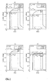
- Figure 2 shows in its four sub-images a, b, c and d several different voltage waveforms, as they can result in the injection of a biphasic current pulse in the body tissue.
- Figure 3 shows a block diagram of one embodiment of the invention.
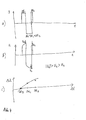
- Figure 4 shows three coordinate systems that show possible current and voltage curves during the measurement process.
- FIG. 5 shows another example of a sequence of biphasic current pulses, which can be used particularly advantageously for a differential measurement of the tissue impedance.
- Figure 1 shows a network of several discrete elements. It results essentially as a series connection of an ohmic resistor R h and a parallel connection of a plurality of resistors and a capacitor C.
- R h here represents the resistance of the heart tissue, in which a measuring electrode is arranged. For the sake of simplicity, other contact resistances of the two measuring electrodes were included in the resistor R h .
- the parallel connection of the capacitance C and the ohmic Resistors R in , R ex and R edema roughly describes the resistance behavior of the lung tissue between the heart and the electromedical implant.
- R in , R ex and C characterize the electrical behavior of the healthy lung tissue, while R edema only occurs when the ohmic resistance of the lung tissue is reduced due to edema formation.
- the ohmic resistance reduced by the edema is taken into account in the electrical equivalent circuit by parallel connection of the resistor R edema .
- the time-invariant part of the measurement voltage generated by the injection of a current pulse depends on the series connection of the resistor R h and the resistors R in , R ex and R edema
- the time-variant part of the measurement voltage alone is the resistors R in , R ex , R edema and the capacity C determined.
- the dependence of the time-variant voltage component of R edema is much stronger than that of the time-invariant one. This illustrates how the validity of the impedance values obtained can be increased by determining the time-variant measured voltage component and, in addition, changes in the resistance R h can be eliminated by scarring the tissue surrounding the measuring electrodes as a source of error in the long-term observation of the development of the tissue impedance values.
- Figure 2 is subdivided into two sub-images, each of which in turn decays into two further sub-images. This results in a total of four partial images, which are named with the letters a to d.
- the first sub-figure shows in the figures a and b, two voltage waveforms, as they could result in the injection of a rectangular current pulse in the body tissue. The two voltage curves were calculated for identical to the value of the resistance R h equivalent circuits of body tissue. In sub-figure b, the value of the resistance R h has been reduced, resulting in a decrease in the maximum value of the voltage profile.
- FIG. 3 The system shown in Figure 3 with a pacemaker 100, a patient device 200 and a Home Monitoring Service Center 300 is intended to serve as an example of a system of the type claimed.
- the pacemaker 100 has for communication with the patient device 200 via a wireless data interface 110, which is connected to the central control unit 120 of the pacemaker 100.
- the control unit 120 is connected to the measurement signal generator 130 and the impedance measurement unit 140 and controls these for determining the impedance of the lung tissue.
- the measurement signal generator 130 has the task of generating measurement signals and outputting them via the connected cardiac electrode 170.
- the housing of the pacemaker 100 serves as the reference electrode. Between the housing and the pacemaker electrode 170 is connected the subtraction unit 160, which is formed from one of the two To deduct electrode applied measuring voltage a constant offset voltage and supply the resulting voltage to the amplifier 150.
- the amplifier 150 amplifies the measurement voltage received from the subtraction unit 160, so that the measurement range of the impedance measurement unit 140 is utilized as completely as possible without overdriving the impedance measurement unit 140.
- the impedance measurement unit 140 determines the measurement voltage applied to its measurement input at the times set by the control unit 120 and outputs a corresponding voltage measurement value to the control unit 120.
- the control unit 120 is configured to store the voltage measurement values received from the impedance measurement unit 140 and at least the difference between two consecutive impedance measurements to calculate. If more than two measurements per output current pulse are carried out or if several different current pulses are output during which an impedance measurement is carried out in each case, the control unit 120 is designed to calculate compensation curve values, so that an error-reduced result value can be provided. This result value and possibly further measurement data are sent by the control unit 120 via the wireless data interface 110 to the patient device 200.
- the patient device 200 has a wireless data interface 210, a control unit 220 and a mobile radio interface 230.
- a wireless data interface 210 receives the patient data sent from the wireless data interface 110 of the pacemaker 100 and forwards it to the control unit 220 of the patient device 200.
- the control unit 220 either forwards the received patient data unmodified via the mobile radio interface 230 to the Home Monitoring Service Center 300 or relieves it by performing tasks that otherwise occur to the monitoring unit 320 of the Home Monitoring Service Center before transmitting the patient data to the Home Monitoring Service Center 300 applies to the patient data.
- the home monitoring service center 300 receives the patient data sent by the patient device 200 via a mobile radio network via the mobile radio interface 310, which is connected to the monitoring unit 320 of the home monitoring service center 300. If the patient device has an interface of the mobile radio interface 230 via an interface for the wired communication, a wired data transmission interface is provided for the Home Monitoring Service Center instead of or in addition to the mobile radio interface 310.
- the home monitoring service center 300 additionally has a memory 330 and a display 340.
- the control unit 320 is configured to store the received patient data in the memory 330 and to calculate short-term and long-term average values of the current and previously received patient data.
- control unit 320 compares the received patient data with the previously calculated short-term and long-term average values of the patient data. In this case, if the control unit 320 determines a discrepancy of the current measured values from the average values, optionally beyond a selectable level, the control unit 320 displays this discrepancy on the display 340 with suitable optical or acoustic means.
- Figure 4 shows three coordinate systems that represent possible waveforms for an impedance measurement.
- a biphasic current pulse is shown, which can be subdivided into three sections, two positive and one negative between these two.
- the pulse duration of the three sections is chosen such that the times ⁇ t 1 and ⁇ t 3 add up exactly to the pulse duration ⁇ t 2 of the negative pulse. This ensures that the integrals of the positive and negative signal components cancel each other out, which guarantees better medical compatibility.
- a qualitative course of a measurement voltage is shown, as it could result from the injection of the biphasic current pulse shown in the first coordinate system.
- a total of three voltage measurements are performed, during each section of the biphasic current pulse. All three Voltage measurements are carried out at a constant time interval to the end of the respective section of the current pulse, resulting in different distances for the three sections to the beginning of the respective section. Due to the different charging times of the electrical capacitance C of the lungs, all three voltage measurements provide different measured values.
- the magnitude of the measured value of the negative portion of the biphasic current pulse is greatest due to the highest charging time, that of the first portion of the current pulse is the second largest and that of the third portion the smallest.
- the measured values relating to the measured value U 3 of the shortest section of the biphasic current pulse were plotted as voltage differences over the time intervals ⁇ t given at each voltage measurement from the beginning of the output of the respective section of the biphasic current pulse. Due to this difference, the resulting voltage difference .DELTA.U 3 gives the shortest portion of the current pulse in the coordinate system to 0.
- the three voltage differences was added to a compensating curve in the coordinate system which follows the known charging characteristic of a capacitor.
- the parameters ⁇ and U 0 which determine the course of this compensation curve can serve as the result of the pulmonary impedance measurement. Alternatively or additionally, the difference of the compensation curve values for the second and third measurement can also be determined.
- Figure 5 shows a further time course of a sequence of current pulses for determining the impedance of the tissue lying between the electrodes. The time of the impedance measurements are marked on the ordinate.
- the measurement is carried out differentially. That is, biphasic current pulses are used which consist of two directly successive equal but opposite polarity current pulses. During each of the two current pulse halves, one measurement is taken at the same time interval performed at the beginning of the delivery of the respective current pulse half. The amounts of the voltages determined in the two partial measurements are added together and the intermediate result is halved. In this way disturbing direct voltages, which could falsify the measurement, are eliminated.
- the sequence of biphasic current pulses shown shows several current pulses of different widths.
- only one differential impedance measurement consisting of two partial measurements is carried out per biphasic current pulse.
- the measurement results of the measurements are evaluated for different widths of current pulses or different times since the beginning of the delivery of the respective current pulse, as already described.
- several measurements per stream pulse half can be carried out. Then the individual measurements must be assigned according to their time interval to the beginning of each current pulse half of the corresponding measurements of the other current pulse half, before the averaging to eliminate disturbing DC voltages and the determination of the capacitive component of the tissue impedance is performed.
Landscapes
- Health & Medical Sciences (AREA)
- Life Sciences & Earth Sciences (AREA)
- Engineering & Computer Science (AREA)
- Molecular Biology (AREA)
- Animal Behavior & Ethology (AREA)
- Biophysics (AREA)
- Pathology (AREA)
- Biomedical Technology (AREA)
- Heart & Thoracic Surgery (AREA)
- Medical Informatics (AREA)
- Veterinary Medicine (AREA)
- Surgery (AREA)
- Physics & Mathematics (AREA)
- General Health & Medical Sciences (AREA)
- Public Health (AREA)
- Computer Networks & Wireless Communication (AREA)
- Nuclear Medicine, Radiotherapy & Molecular Imaging (AREA)
- Radiology & Medical Imaging (AREA)
- Measurement And Recording Of Electrical Phenomena And Electrical Characteristics Of The Living Body (AREA)
- Electrotherapy Devices (AREA)
Applications Claiming Priority (1)
| Application Number | Priority Date | Filing Date | Title |
|---|---|---|---|
| DE102004059082A DE102004059082A1 (de) | 2004-12-02 | 2004-12-02 | Vorrichtung zum Bestimmen der Thorax-Impedanz |
Publications (3)
| Publication Number | Publication Date |
|---|---|
| EP1665983A2 true EP1665983A2 (fr) | 2006-06-07 |
| EP1665983A3 EP1665983A3 (fr) | 2008-09-10 |
| EP1665983B1 EP1665983B1 (fr) | 2015-02-25 |
Family
ID=36124144
Family Applications (1)
| Application Number | Title | Priority Date | Filing Date |
|---|---|---|---|
| EP05024364.1A Expired - Lifetime EP1665983B1 (fr) | 2004-12-02 | 2005-11-09 | Appareil de détermination de l'impédance du thorax |
Country Status (3)
| Country | Link |
|---|---|
| US (1) | US8060196B2 (fr) |
| EP (1) | EP1665983B1 (fr) |
| DE (1) | DE102004059082A1 (fr) |
Cited By (5)
| Publication number | Priority date | Publication date | Assignee | Title |
|---|---|---|---|---|
| EP2016892A1 (fr) | 2007-07-20 | 2009-01-21 | BIOTRONIK CRM Patent AG | Appareil médical implantable |
| EP2075033A1 (fr) | 2007-12-20 | 2009-07-01 | BIOTRONIK CRM Patent AG | Stimulateur cardiaque biventriculair |
| DE102008010651A1 (de) | 2008-02-22 | 2009-09-03 | Biotronik Crm Patent Ag | System und Verfahren zur Auswertung eines Impedanzverlaufs |
| EP2241249A1 (fr) | 2009-04-15 | 2010-10-20 | Biotronik CRM Patent AG | Dispositif et procédé de traitement de valeurs de mesure physiologiques |
| EP2364643A1 (fr) * | 2010-03-09 | 2011-09-14 | BIOTRONIK SE & Co. KG | Implant électromédical et système de surveillance doté de cet implant électromédical |
Families Citing this family (56)
| Publication number | Priority date | Publication date | Assignee | Title |
|---|---|---|---|---|
| AUPQ113799A0 (en) | 1999-06-22 | 1999-07-15 | University Of Queensland, The | A method and device for measuring lymphoedema |
| US8068906B2 (en) * | 2004-06-21 | 2011-11-29 | Aorora Technologies Pty Ltd | Cardiac monitoring system |
| US7387610B2 (en) | 2004-08-19 | 2008-06-17 | Cardiac Pacemakers, Inc. | Thoracic impedance detection with blood resistivity compensation |
| US7603170B2 (en) | 2005-04-26 | 2009-10-13 | Cardiac Pacemakers, Inc. | Calibration of impedance monitoring of respiratory volumes using thoracic D.C. impedance |
| US7907997B2 (en) | 2005-05-11 | 2011-03-15 | Cardiac Pacemakers, Inc. | Enhancements to the detection of pulmonary edema when using transthoracic impedance |
| US7340296B2 (en) * | 2005-05-18 | 2008-03-04 | Cardiac Pacemakers, Inc. | Detection of pleural effusion using transthoracic impedance |
| US7644714B2 (en) | 2005-05-27 | 2010-01-12 | Apnex Medical, Inc. | Devices and methods for treating sleep disorders |
| AU2006265763B2 (en) | 2005-07-01 | 2012-08-09 | Impedimed Limited | Monitoring system |
| CA2608962C (fr) | 2005-07-01 | 2016-12-06 | Scott Chetham | Systeme de surveillance |
| JP5034028B2 (ja) * | 2005-07-01 | 2012-09-26 | インペダイムド・リミテッド | 肺モニタリングシステム |
| WO2007009183A1 (fr) * | 2005-07-20 | 2007-01-25 | Impedance Cardiology Systems, Inc. | Determination d'indice |
| WO2007041783A1 (fr) | 2005-10-11 | 2007-04-19 | Impedance Cardiology Systems, Inc. | Surveillance de l'etat d'hydratation |
| US8600497B1 (en) * | 2006-03-31 | 2013-12-03 | Pacesetter, Inc. | Systems and methods to monitor and treat heart failure conditions |
| US7794404B1 (en) | 2006-03-31 | 2010-09-14 | Pacesetter, Inc | System and method for estimating cardiac pressure using parameters derived from impedance signals detected by an implantable medical device |
| US8712519B1 (en) | 2006-03-31 | 2014-04-29 | Pacesetter, Inc. | Closed-loop adaptive adjustment of pacing therapy based on cardiogenic impedance signals detected by an implantable medical device |
| JP5431147B2 (ja) | 2006-05-30 | 2014-03-05 | インぺディメッド リミテッド | インピーダンス測定 |
| WO2008007638A1 (fr) * | 2006-07-10 | 2008-01-17 | Panasonic Corporation | Dispositif mesurant la conductivité de la peau |
| US9186511B2 (en) | 2006-10-13 | 2015-11-17 | Cyberonics, Inc. | Obstructive sleep apnea treatment devices, systems and methods |
| US9205262B2 (en) | 2011-05-12 | 2015-12-08 | Cyberonics, Inc. | Devices and methods for sleep apnea treatment |
| US9913982B2 (en) | 2011-01-28 | 2018-03-13 | Cyberonics, Inc. | Obstructive sleep apnea treatment devices, systems and methods |
| US8855771B2 (en) | 2011-01-28 | 2014-10-07 | Cyberonics, Inc. | Screening devices and methods for obstructive sleep apnea therapy |
| DE202007019439U1 (de) | 2006-10-13 | 2012-09-12 | Apnex Medical, Inc. | Geräte, Systeme und Methoden zur Behandlung von obstruktiver Schalfapnoe |
| US9744354B2 (en) | 2008-12-31 | 2017-08-29 | Cyberonics, Inc. | Obstructive sleep apnea treatment devices, systems and methods |
| CA2670293C (fr) | 2006-11-30 | 2017-01-03 | Impedimed Limited | Appareil de mesure |
| US8504153B2 (en) | 2007-04-04 | 2013-08-06 | Pacesetter, Inc. | System and method for estimating cardiac pressure based on cardiac electrical conduction delays using an implantable medical device |
| US8208999B2 (en) | 2007-04-04 | 2012-06-26 | Pacesetter, Inc. | System and method for estimating electrical conduction delays from immittance values measured using an implantable medical device |
| EP2148613B9 (fr) | 2007-04-20 | 2014-12-10 | Impedimed Limited | Systeme et sonde de surveillance |
| EP2175776B1 (fr) | 2007-08-09 | 2016-03-23 | Impedimed Limited | Mesure de l'impédance |
| US8352033B2 (en) | 2007-10-15 | 2013-01-08 | Mark Kroll | Apparatus and methods for measuring defibrillation lead impedance via a high magnitude, short duration current pulse |
| US8195294B2 (en) * | 2008-04-30 | 2012-06-05 | Medtronic, Inc. | Multi-stage testing of electrodes of implantable medical device, system and method |
| JP5547200B2 (ja) | 2008-10-01 | 2014-07-09 | インスパイア・メディカル・システムズ・インコーポレイテッド | 睡眠時無呼吸を治療する経静脈法 |
| JP5575789B2 (ja) | 2008-11-19 | 2014-08-20 | インスパイア・メディカル・システムズ・インコーポレイテッド | 睡眠呼吸障害の治療方法 |
| EP2348987B1 (fr) | 2008-11-28 | 2017-03-22 | Impedimed Limited | Procédé de mesure d'impédance |
| US9486628B2 (en) | 2009-03-31 | 2016-11-08 | Inspire Medical Systems, Inc. | Percutaneous access for systems and methods of treating sleep apnea |
| US8825158B2 (en) | 2009-08-25 | 2014-09-02 | Lamda Nu, Llc | Method and apparatus for detection of lead conductor anomalies using dynamic electrical parameters |
| WO2011050393A1 (fr) | 2009-10-26 | 2011-05-05 | Impedimed Limited | Détermination d'indicateur de niveau de fluide |
| WO2011060497A1 (fr) | 2009-11-18 | 2011-05-26 | Impedimed Limited | Distribution de signal pour des mesures d'électrode de patient |
| WO2011063858A1 (fr) | 2009-11-30 | 2011-06-03 | St. Jude Medical Ab | Procédé et dispositif de détection de bruit |
| EP2364644B1 (fr) * | 2010-03-09 | 2016-04-13 | BIOTRONIK SE & Co. KG | Implant électromédical et système de surveillance |
| JP6092212B2 (ja) | 2011-08-11 | 2017-03-08 | インスパイア・メディカル・システムズ・インコーポレイテッドInspire Medical Systems, Inc. | 呼吸努力の検知結果に基づいて刺激プロトコルを選択するためのシステム |
| US8934992B2 (en) | 2011-09-01 | 2015-01-13 | Inspire Medical Systems, Inc. | Nerve cuff |
| JP2015512658A (ja) | 2011-12-14 | 2015-04-30 | インターセクション・メディカル・インコーポレイテッドIntersection Medical,Inc. | 組織内の周波数に対する表面下抵抗率の相対的空間変化を決定するためのデバイス、システム及び方法 |
| US8812103B2 (en) | 2012-06-01 | 2014-08-19 | Lamda Nu, Llc | Method for detecting and treating insulation lead-to-housing failures |
| US9272150B2 (en) | 2012-06-01 | 2016-03-01 | Lambda Nu Technology Llc | Method for detecting and localizing insulation failures of implantable device leads |
| US9675799B2 (en) | 2012-12-05 | 2017-06-13 | Lambda Nu Technology Llc | Method and apparatus for implantable cardiac lead integrity analysis |
| US10039919B2 (en) | 2013-04-30 | 2018-08-07 | Lambda Nu Technology Llc | Methods and apparatus for detecting and localizing partial conductor failures of implantable device leads |
| US9486624B2 (en) | 2013-06-13 | 2016-11-08 | Lambda Nu Technology Llc | Detection of implantable lead failures by differential EGM analysis |
| US10118031B2 (en) | 2013-06-28 | 2018-11-06 | Lambda Nu Technology Llc | Method and apparatus for implantable cardiac lead integrity analysis |
| WO2015123360A1 (fr) | 2014-02-11 | 2015-08-20 | Cyberonics, Inc. | Systèmes et des procédés de détection et de traitement de l'apnée obstructive du sommeil |
| US9636500B2 (en) | 2014-03-25 | 2017-05-02 | Lambda Nu Technology Llc | Active surveillance of implanted medical leads for lead integrity |
| US10898709B2 (en) | 2015-03-19 | 2021-01-26 | Inspire Medical Systems, Inc. | Stimulation for treating sleep disordered breathing |
| US10555686B1 (en) | 2015-07-01 | 2020-02-11 | Richard C. Kimoto | Removing parasitic effects from body impedance measurements with wrist-worn and/or other devices |
| US10252069B1 (en) | 2015-11-19 | 2019-04-09 | Lambda Nu Technology Llc | Micro-charge ICD lead testing method and apparatus |
| US10543364B2 (en) | 2017-04-07 | 2020-01-28 | Lambda Nu Technology Llc | Detection of lead electrode dislodgement using cavitary electrogram |
| WO2019032890A1 (fr) | 2017-08-11 | 2019-02-14 | Inspire Medical Systems, Inc. | Électrode à manchon |
| EP3788948A1 (fr) * | 2019-09-04 | 2021-03-10 | Universitat Pompeu Fabra | Système de détection électronique implantable permettant de mesurer et de surveiller des paramètres médicaux |
Citations (5)
| Publication number | Priority date | Publication date | Assignee | Title |
|---|---|---|---|---|
| US5752976A (en) | 1995-06-23 | 1998-05-19 | Medtronic, Inc. | World wide patient location and data telemetry system for implantable medical devices |
| US5957861A (en) | 1997-01-31 | 1999-09-28 | Medtronic, Inc. | Impedance monitor for discerning edema through evaluation of respiratory rate |
| US6473640B1 (en) | 1999-01-25 | 2002-10-29 | Jay Erlebacher | Implantable device and method for long-term detection and monitoring of congestive heart failure |
| US6553262B1 (en) | 1998-09-18 | 2003-04-22 | Biotronik Mess-Und Therapiegerate Gmbh & Co. Ingenieurburo Berlin | Arrangement for patient monitoring |
| US20040102712A1 (en) | 2002-11-25 | 2004-05-27 | Andres Belalcazar | Impedance monitoring for detecting pulmonary edema and thoracic congestion |
Family Cites Families (10)
| Publication number | Priority date | Publication date | Assignee | Title |
|---|---|---|---|---|
| FR2714611B1 (fr) * | 1993-12-31 | 1996-03-15 | Ela Medical Sa | Procédé de contrôle d'un dispositif implantable actif. |
| US6253103B1 (en) * | 1996-04-16 | 2001-06-26 | Kimberly-Clark Worldwide, Inc. | Method and apparatus for high current electrode, transthoracic and transmyocardial impedance estimation |
| US6148233A (en) * | 1997-03-07 | 2000-11-14 | Cardiac Science, Inc. | Defibrillation system having segmented electrodes |
| US6104949A (en) * | 1998-09-09 | 2000-08-15 | Vitatron Medical, B.V. | Medical device |
| US6512949B1 (en) * | 1999-07-12 | 2003-01-28 | Medtronic, Inc. | Implantable medical device for measuring time varying physiologic conditions especially edema and for responding thereto |
| US6360123B1 (en) * | 1999-08-24 | 2002-03-19 | Impulse Dynamics N.V. | Apparatus and method for determining a mechanical property of an organ or body cavity by impedance determination |
| US6336903B1 (en) * | 1999-11-16 | 2002-01-08 | Cardiac Intelligence Corp. | Automated collection and analysis patient care system and method for diagnosing and monitoring congestive heart failure and outcomes thereof |
| ITBO20010110A1 (it) * | 2001-03-01 | 2002-09-01 | Tre Esse Progettazione Biomedi | Procedimento e dispositivo impiantabile per la misura intrapolmonare di proprieta' fisiche del tessuto polmonare dipendenti dalla sua densit |
| DE10148440A1 (de) * | 2001-10-01 | 2003-04-17 | Inflow Dynamics Inc | Vorrichtung zum Überwachen eines Blutstaus im Herzen |
| US6931272B2 (en) * | 2003-04-29 | 2005-08-16 | Medtronic, Inc. | Method and apparatus to monitor pulmonary edema |
-
2004
- 2004-12-02 DE DE102004059082A patent/DE102004059082A1/de not_active Withdrawn
-
2005
- 2005-11-09 EP EP05024364.1A patent/EP1665983B1/fr not_active Expired - Lifetime
- 2005-12-02 US US11/293,398 patent/US8060196B2/en not_active Expired - Fee Related
Patent Citations (5)
| Publication number | Priority date | Publication date | Assignee | Title |
|---|---|---|---|---|
| US5752976A (en) | 1995-06-23 | 1998-05-19 | Medtronic, Inc. | World wide patient location and data telemetry system for implantable medical devices |
| US5957861A (en) | 1997-01-31 | 1999-09-28 | Medtronic, Inc. | Impedance monitor for discerning edema through evaluation of respiratory rate |
| US6553262B1 (en) | 1998-09-18 | 2003-04-22 | Biotronik Mess-Und Therapiegerate Gmbh & Co. Ingenieurburo Berlin | Arrangement for patient monitoring |
| US6473640B1 (en) | 1999-01-25 | 2002-10-29 | Jay Erlebacher | Implantable device and method for long-term detection and monitoring of congestive heart failure |
| US20040102712A1 (en) | 2002-11-25 | 2004-05-27 | Andres Belalcazar | Impedance monitoring for detecting pulmonary edema and thoracic congestion |
Non-Patent Citations (1)
| Title |
|---|
| PALKO: "Multifrequency Device for Measurement of the Complex Electrical Bio-Impedance - Design and Application", PROCEEDINGS RC IEEE-EMBS & 14TH BMESI, vol. 1, 1995, pages 45 |
Cited By (10)
| Publication number | Priority date | Publication date | Assignee | Title |
|---|---|---|---|---|
| EP2016892A1 (fr) | 2007-07-20 | 2009-01-21 | BIOTRONIK CRM Patent AG | Appareil médical implantable |
| EP2075033A1 (fr) | 2007-12-20 | 2009-07-01 | BIOTRONIK CRM Patent AG | Stimulateur cardiaque biventriculair |
| DE102008010651A1 (de) | 2008-02-22 | 2009-09-03 | Biotronik Crm Patent Ag | System und Verfahren zur Auswertung eines Impedanzverlaufs |
| US8792970B2 (en) | 2008-02-22 | 2014-07-29 | Biotronik Crm Patent Ag | System and method for analyzing an impedance course |
| DE102008010651B4 (de) | 2008-02-22 | 2019-04-25 | Biotronik Se & Co. Kg | System und Verfahren zur Auswertung eines Impedanzverlaufs |
| EP2241249A1 (fr) | 2009-04-15 | 2010-10-20 | Biotronik CRM Patent AG | Dispositif et procédé de traitement de valeurs de mesure physiologiques |
| DE102009002399A1 (de) | 2009-04-15 | 2010-10-21 | Biotronik Crm Patent Ag | Vorrichtung und Verfahren zum Verarbeiten physiologischer Messwerte |
| US8571641B2 (en) | 2009-04-15 | 2013-10-29 | Biotronik Crm Patent Ag | Apparatus and method for processing physiological measurement values |
| EP2364643A1 (fr) * | 2010-03-09 | 2011-09-14 | BIOTRONIK SE & Co. KG | Implant électromédical et système de surveillance doté de cet implant électromédical |
| US8491485B2 (en) | 2010-03-09 | 2013-07-23 | Biotronik Se & Co. Kg | Electromedical implant and monitoring system including the electromedical implant |
Also Published As
| Publication number | Publication date |
|---|---|
| US8060196B2 (en) | 2011-11-15 |
| EP1665983A3 (fr) | 2008-09-10 |
| EP1665983B1 (fr) | 2015-02-25 |
| DE102004059082A1 (de) | 2006-06-08 |
| US20060135886A1 (en) | 2006-06-22 |
Similar Documents
| Publication | Publication Date | Title |
|---|---|---|
| EP1665983B1 (fr) | Appareil de détermination de l'impédance du thorax | |
| DE69926347T2 (de) | Vorrichtung zur steuerung des herzrhythmus unter verwendung der transthorakalen impedanz | |
| EP1586348B1 (fr) | Dispositif d'électrothérapie | |
| DE69125517T2 (de) | Änderungen des Herzkammervolumens oder -drucks als Steuerparameter | |
| DE3854732T2 (de) | Physiologische Herz- und Lungenuntersuchung durch intrakardielle Messungen mit einem einzelnen Sensor. | |
| DE102008010651B4 (de) | System und Verfahren zur Auswertung eines Impedanzverlaufs | |
| DE3442174C2 (de) | Verfahren und Vorrichtung zum Messen eines Indikators für den Entspannungszustand eines Menschen | |
| DE60119817T2 (de) | Aktive implantierbare medizinische Vorrichtung mit Mitteln zur Messung der transseptalen Bioimpedanz | |
| DE60036396T2 (de) | Implantierbare vorrichtung zur steuerung des herzrhythmus durch bestimmung des zustandes von chf-patienten | |
| DE69331961T2 (de) | Frequenzadaptiver Herzschrittmacher gesteuert mittels unipolar gemessener Impedanz | |
| DE60203249T2 (de) | Vorrichtung zur Diagnose von Schlafapnoe | |
| DE60106645T2 (de) | Apparat zur messung des mittleren blutdruckes in der lungenarterie von der herzkammer aus mit einem mobilen überwachungsgerät | |
| EP1955650B1 (fr) | Appareil médical implantable | |
| EP2415396B1 (fr) | Moniteur cardiaque | |
| EP2364644B1 (fr) | Implant électromédical et système de surveillance | |
| DE602005001645T2 (de) | Aktives implantierbares medizinisches Gerät mit respiratorischen Diagnosemitteln und verbesserter Detektion von respiratorischen Artefakten | |
| DE102009002399A1 (de) | Vorrichtung und Verfahren zum Verarbeiten physiologischer Messwerte | |
| DE102007058788A1 (de) | Schätzverfahren für die Impedanz von Festgewebe, Herzminutenvolumen-Berechnungsverfahren, Berechnungsverfahren für den pulmonalen Kapillardruck, Überwachungsgerät für das Herzminutenvolumen, Herzminutenvolumen-Überwachungssystem, Überwachungsgerät für den pulmonalen Kapillardruck und Überwachungssystem für den pulmonalen Kapillardruck | |
| WO1997009928A1 (fr) | Procede et dispositif pour la determination du debit cardiaque | |
| EP2364643B1 (fr) | Implant électromédical et système de surveillance doté de cet implant électromédical | |
| DE102016112391A1 (de) | Behandlungsliege | |
| DE112012000564T5 (de) | Verbessertes Verfahren zum Erfassen von Schlafapnoe und Behandlung davon | |
| DE602004012899T2 (de) | Nachweis und/oder überwachung von diastolischer herzinsuffizienz | |
| DE60304202T2 (de) | Überwachungsgerät für dekompensierte herzinsuffizienz | |
| DE102022101845A1 (de) | Beatmungsvorrichtung, Verfahren, Computerprogramm und Vorrichtung zum Ermitteln eines Maßes für einen intrinsischen endexspiratorischen Druck |
Legal Events
| Date | Code | Title | Description |
|---|---|---|---|
| PUAI | Public reference made under article 153(3) epc to a published international application that has entered the european phase |
Free format text: ORIGINAL CODE: 0009012 |
|
| AK | Designated contracting states |
Kind code of ref document: A2 Designated state(s): AT BE BG CH CY CZ DE DK EE ES FI FR GB GR HU IE IS IT LI LT LU LV MC NL PL PT RO SE SI SK TR |
|
| AX | Request for extension of the european patent |
Extension state: AL BA HR MK YU |
|
| PUAL | Search report despatched |
Free format text: ORIGINAL CODE: 0009013 |
|
| AK | Designated contracting states |
Kind code of ref document: A3 Designated state(s): AT BE BG CH CY CZ DE DK EE ES FI FR GB GR HU IE IS IT LI LT LU LV MC NL PL PT RO SE SI SK TR |
|
| AX | Request for extension of the european patent |
Extension state: AL BA HR MK YU |
|
| 17P | Request for examination filed |
Effective date: 20090219 |
|
| 17Q | First examination report despatched |
Effective date: 20090324 |
|
| AKX | Designation fees paid |
Designated state(s): AT BE BG CH CY CZ DE DK EE ES FI FR GB GR HU IE IS IT LI LT LU LV MC NL PL PT RO SE SI SK TR |
|
| GRAP | Despatch of communication of intention to grant a patent |
Free format text: ORIGINAL CODE: EPIDOSNIGR1 |
|
| INTG | Intention to grant announced |
Effective date: 20141009 |
|
| GRAS | Grant fee paid |
Free format text: ORIGINAL CODE: EPIDOSNIGR3 |
|
| GRAA | (expected) grant |
Free format text: ORIGINAL CODE: 0009210 |
|
| AK | Designated contracting states |
Kind code of ref document: B1 Designated state(s): AT BE BG CH CY CZ DE DK EE ES FI FR GB GR HU IE IS IT LI LT LU LV MC NL PL PT RO SE SI SK TR |
|
| REG | Reference to a national code |
Ref country code: GB Ref legal event code: FG4D Free format text: NOT ENGLISH Ref country code: DE Ref legal event code: R081 Ref document number: 502005014690 Country of ref document: DE Owner name: BIOTRONIK SE & CO. KG, DE Free format text: FORMER OWNER: BIOTRONIK CRM PATENT AG, BAAR, CH |
|
| REG | Reference to a national code |
Ref country code: CH Ref legal event code: EP |
|
| REG | Reference to a national code |
Ref country code: IE Ref legal event code: FG4D Free format text: LANGUAGE OF EP DOCUMENT: GERMAN |
|
| REG | Reference to a national code |
Ref country code: DE Ref legal event code: R096 Ref document number: 502005014690 Country of ref document: DE Effective date: 20150402 |
|
| REG | Reference to a national code |
Ref country code: AT Ref legal event code: REF Ref document number: 711210 Country of ref document: AT Kind code of ref document: T Effective date: 20150415 |
|
| REG | Reference to a national code |
Ref country code: NL Ref legal event code: VDEP Effective date: 20150225 |
|
| REG | Reference to a national code |
Ref country code: DE Ref legal event code: R082 Ref document number: 502005014690 Country of ref document: DE Representative=s name: RANDOLL, SOEREN, DIPL.-CHEM. UNIV. DR. RER. NA, DE Ref country code: DE Ref legal event code: R082 Ref document number: 502005014690 Country of ref document: DE |
|
| REG | Reference to a national code |
Ref country code: LT Ref legal event code: MG4D |
|
| PG25 | Lapsed in a contracting state [announced via postgrant information from national office to epo] |
Ref country code: SE Free format text: LAPSE BECAUSE OF FAILURE TO SUBMIT A TRANSLATION OF THE DESCRIPTION OR TO PAY THE FEE WITHIN THE PRESCRIBED TIME-LIMIT Effective date: 20150225 Ref country code: LT Free format text: LAPSE BECAUSE OF FAILURE TO SUBMIT A TRANSLATION OF THE DESCRIPTION OR TO PAY THE FEE WITHIN THE PRESCRIBED TIME-LIMIT Effective date: 20150225 Ref country code: FI Free format text: LAPSE BECAUSE OF FAILURE TO SUBMIT A TRANSLATION OF THE DESCRIPTION OR TO PAY THE FEE WITHIN THE PRESCRIBED TIME-LIMIT Effective date: 20150225 Ref country code: ES Free format text: LAPSE BECAUSE OF FAILURE TO SUBMIT A TRANSLATION OF THE DESCRIPTION OR TO PAY THE FEE WITHIN THE PRESCRIBED TIME-LIMIT Effective date: 20150225 |
|
| PG25 | Lapsed in a contracting state [announced via postgrant information from national office to epo] |
Ref country code: LV Free format text: LAPSE BECAUSE OF FAILURE TO SUBMIT A TRANSLATION OF THE DESCRIPTION OR TO PAY THE FEE WITHIN THE PRESCRIBED TIME-LIMIT Effective date: 20150225 Ref country code: GR Free format text: LAPSE BECAUSE OF FAILURE TO SUBMIT A TRANSLATION OF THE DESCRIPTION OR TO PAY THE FEE WITHIN THE PRESCRIBED TIME-LIMIT Effective date: 20150526 Ref country code: IS Free format text: LAPSE BECAUSE OF FAILURE TO SUBMIT A TRANSLATION OF THE DESCRIPTION OR TO PAY THE FEE WITHIN THE PRESCRIBED TIME-LIMIT Effective date: 20150625 |
|
| PG25 | Lapsed in a contracting state [announced via postgrant information from national office to epo] |
Ref country code: NL Free format text: LAPSE BECAUSE OF FAILURE TO SUBMIT A TRANSLATION OF THE DESCRIPTION OR TO PAY THE FEE WITHIN THE PRESCRIBED TIME-LIMIT Effective date: 20150225 |
|
| PG25 | Lapsed in a contracting state [announced via postgrant information from national office to epo] |
Ref country code: CZ Free format text: LAPSE BECAUSE OF FAILURE TO SUBMIT A TRANSLATION OF THE DESCRIPTION OR TO PAY THE FEE WITHIN THE PRESCRIBED TIME-LIMIT Effective date: 20150225 Ref country code: SK Free format text: LAPSE BECAUSE OF FAILURE TO SUBMIT A TRANSLATION OF THE DESCRIPTION OR TO PAY THE FEE WITHIN THE PRESCRIBED TIME-LIMIT Effective date: 20150225 Ref country code: EE Free format text: LAPSE BECAUSE OF FAILURE TO SUBMIT A TRANSLATION OF THE DESCRIPTION OR TO PAY THE FEE WITHIN THE PRESCRIBED TIME-LIMIT Effective date: 20150225 Ref country code: DK Free format text: LAPSE BECAUSE OF FAILURE TO SUBMIT A TRANSLATION OF THE DESCRIPTION OR TO PAY THE FEE WITHIN THE PRESCRIBED TIME-LIMIT Effective date: 20150225 Ref country code: RO Free format text: LAPSE BECAUSE OF FAILURE TO SUBMIT A TRANSLATION OF THE DESCRIPTION OR TO PAY THE FEE WITHIN THE PRESCRIBED TIME-LIMIT Effective date: 20150225 |
|
| REG | Reference to a national code |
Ref country code: DE Ref legal event code: R097 Ref document number: 502005014690 Country of ref document: DE |
|
| PG25 | Lapsed in a contracting state [announced via postgrant information from national office to epo] |
Ref country code: PL Free format text: LAPSE BECAUSE OF FAILURE TO SUBMIT A TRANSLATION OF THE DESCRIPTION OR TO PAY THE FEE WITHIN THE PRESCRIBED TIME-LIMIT Effective date: 20150225 |
|
| PG25 | Lapsed in a contracting state [announced via postgrant information from national office to epo] |
Ref country code: IT Free format text: LAPSE BECAUSE OF FAILURE TO SUBMIT A TRANSLATION OF THE DESCRIPTION OR TO PAY THE FEE WITHIN THE PRESCRIBED TIME-LIMIT Effective date: 20150225 |
|
| PLBE | No opposition filed within time limit |
Free format text: ORIGINAL CODE: 0009261 |
|
| STAA | Information on the status of an ep patent application or granted ep patent |
Free format text: STATUS: NO OPPOSITION FILED WITHIN TIME LIMIT |
|
| 26N | No opposition filed |
Effective date: 20151126 |
|
| PG25 | Lapsed in a contracting state [announced via postgrant information from national office to epo] |
Ref country code: SI Free format text: LAPSE BECAUSE OF FAILURE TO SUBMIT A TRANSLATION OF THE DESCRIPTION OR TO PAY THE FEE WITHIN THE PRESCRIBED TIME-LIMIT Effective date: 20150225 |
|
| PG25 | Lapsed in a contracting state [announced via postgrant information from national office to epo] |
Ref country code: LU Free format text: LAPSE BECAUSE OF FAILURE TO SUBMIT A TRANSLATION OF THE DESCRIPTION OR TO PAY THE FEE WITHIN THE PRESCRIBED TIME-LIMIT Effective date: 20151109 Ref country code: MC Free format text: LAPSE BECAUSE OF FAILURE TO SUBMIT A TRANSLATION OF THE DESCRIPTION OR TO PAY THE FEE WITHIN THE PRESCRIBED TIME-LIMIT Effective date: 20150225 |
|
| GBPC | Gb: european patent ceased through non-payment of renewal fee |
Effective date: 20151109 |
|
| REG | Reference to a national code |
Ref country code: FR Ref legal event code: ST Effective date: 20160729 |
|
| PG25 | Lapsed in a contracting state [announced via postgrant information from national office to epo] |
Ref country code: GB Free format text: LAPSE BECAUSE OF NON-PAYMENT OF DUE FEES Effective date: 20151109 |
|
| PG25 | Lapsed in a contracting state [announced via postgrant information from national office to epo] |
Ref country code: FR Free format text: LAPSE BECAUSE OF NON-PAYMENT OF DUE FEES Effective date: 20151130 |
|
| REG | Reference to a national code |
Ref country code: AT Ref legal event code: MM01 Ref document number: 711210 Country of ref document: AT Kind code of ref document: T Effective date: 20151109 |
|
| PG25 | Lapsed in a contracting state [announced via postgrant information from national office to epo] |
Ref country code: AT Free format text: LAPSE BECAUSE OF NON-PAYMENT OF DUE FEES Effective date: 20151109 |
|
| PG25 | Lapsed in a contracting state [announced via postgrant information from national office to epo] |
Ref country code: HU Free format text: LAPSE BECAUSE OF FAILURE TO SUBMIT A TRANSLATION OF THE DESCRIPTION OR TO PAY THE FEE WITHIN THE PRESCRIBED TIME-LIMIT; INVALID AB INITIO Effective date: 20051109 Ref country code: BG Free format text: LAPSE BECAUSE OF FAILURE TO SUBMIT A TRANSLATION OF THE DESCRIPTION OR TO PAY THE FEE WITHIN THE PRESCRIBED TIME-LIMIT Effective date: 20150225 |
|
| PG25 | Lapsed in a contracting state [announced via postgrant information from national office to epo] |
Ref country code: CY Free format text: LAPSE BECAUSE OF FAILURE TO SUBMIT A TRANSLATION OF THE DESCRIPTION OR TO PAY THE FEE WITHIN THE PRESCRIBED TIME-LIMIT Effective date: 20150225 |
|
| PG25 | Lapsed in a contracting state [announced via postgrant information from national office to epo] |
Ref country code: BE Free format text: LAPSE BECAUSE OF NON-PAYMENT OF DUE FEES Effective date: 20151130 |
|
| PG25 | Lapsed in a contracting state [announced via postgrant information from national office to epo] |
Ref country code: TR Free format text: LAPSE BECAUSE OF FAILURE TO SUBMIT A TRANSLATION OF THE DESCRIPTION OR TO PAY THE FEE WITHIN THE PRESCRIBED TIME-LIMIT Effective date: 20150225 |
|
| REG | Reference to a national code |
Ref country code: DE Ref legal event code: R082 Ref document number: 502005014690 Country of ref document: DE Ref country code: DE Ref legal event code: R081 Ref document number: 502005014690 Country of ref document: DE Owner name: BIOTRONIK SE & CO. KG, DE Free format text: FORMER OWNER: BIOTRONIK CRM PATENT AG, BAAR, CH |
|
| PG25 | Lapsed in a contracting state [announced via postgrant information from national office to epo] |
Ref country code: PT Free format text: LAPSE BECAUSE OF FAILURE TO SUBMIT A TRANSLATION OF THE DESCRIPTION OR TO PAY THE FEE WITHIN THE PRESCRIBED TIME-LIMIT Effective date: 20150225 |
|
| PGFP | Annual fee paid to national office [announced via postgrant information from national office to epo] |
Ref country code: DE Payment date: 20211126 Year of fee payment: 17 Ref country code: IE Payment date: 20211118 Year of fee payment: 17 |
|
| PGFP | Annual fee paid to national office [announced via postgrant information from national office to epo] |
Ref country code: CH Payment date: 20211123 Year of fee payment: 17 |
|
| REG | Reference to a national code |
Ref country code: DE Ref legal event code: R119 Ref document number: 502005014690 Country of ref document: DE |
|
| REG | Reference to a national code |
Ref country code: CH Ref legal event code: PL |
|
| PG25 | Lapsed in a contracting state [announced via postgrant information from national office to epo] |
Ref country code: LI Free format text: LAPSE BECAUSE OF NON-PAYMENT OF DUE FEES Effective date: 20221130 Ref country code: CH Free format text: LAPSE BECAUSE OF NON-PAYMENT OF DUE FEES Effective date: 20221130 |
|
| PG25 | Lapsed in a contracting state [announced via postgrant information from national office to epo] |
Ref country code: IE Free format text: LAPSE BECAUSE OF NON-PAYMENT OF DUE FEES Effective date: 20221109 Ref country code: DE Free format text: LAPSE BECAUSE OF NON-PAYMENT OF DUE FEES Effective date: 20230601 |