EP2016892A1 - Appareil médical implantable - Google Patents
Appareil médical implantable Download PDFInfo
- Publication number
- EP2016892A1 EP2016892A1 EP08158972A EP08158972A EP2016892A1 EP 2016892 A1 EP2016892 A1 EP 2016892A1 EP 08158972 A EP08158972 A EP 08158972A EP 08158972 A EP08158972 A EP 08158972A EP 2016892 A1 EP2016892 A1 EP 2016892A1
- Authority
- EP
- European Patent Office
- Prior art keywords
- medical device
- implantable medical
- sensor
- control unit
- sensor output
- Prior art date
- Legal status (The legal status is an assumption and is not a legal conclusion. Google has not performed a legal analysis and makes no representation as to the accuracy of the status listed.)
- Withdrawn
Links
- 238000002513 implantation Methods 0.000 claims abstract description 16
- 238000000034 method Methods 0.000 claims abstract description 6
- 230000008569 process Effects 0.000 claims abstract description 6
- 230000008054 signal transmission Effects 0.000 claims abstract description 3
- 239000012530 fluid Substances 0.000 claims description 38
- 239000003814 drug Substances 0.000 claims description 16
- 229940079593 drug Drugs 0.000 claims description 14
- 230000008859 change Effects 0.000 claims description 13
- 238000001514 detection method Methods 0.000 claims description 7
- 230000001575 pathological effect Effects 0.000 claims description 7
- 230000005540 biological transmission Effects 0.000 claims description 6
- 238000002604 ultrasonography Methods 0.000 claims description 5
- 239000002260 anti-inflammatory agent Substances 0.000 claims description 4
- 229940124599 anti-inflammatory drug Drugs 0.000 claims description 4
- 210000001124 body fluid Anatomy 0.000 claims description 4
- 239000010839 body fluid Substances 0.000 claims description 4
- 230000000694 effects Effects 0.000 claims description 4
- 230000005484 gravity Effects 0.000 claims description 4
- 230000007423 decrease Effects 0.000 claims description 3
- 229960003957 dexamethasone Drugs 0.000 claims description 3
- UREBDLICKHMUKA-CXSFZGCWSA-N dexamethasone Chemical compound C1CC2=CC(=O)C=C[C@]2(C)[C@]2(F)[C@@H]1[C@@H]1C[C@@H](C)[C@@](C(=O)CO)(O)[C@@]1(C)C[C@@H]2O UREBDLICKHMUKA-CXSFZGCWSA-N 0.000 claims description 3
- 230000007774 longterm Effects 0.000 claims description 3
- 238000005259 measurement Methods 0.000 claims description 3
- 229960005205 prednisolone Drugs 0.000 claims description 3
- OIGNJSKKLXVSLS-VWUMJDOOSA-N prednisolone Chemical compound O=C1C=C[C@]2(C)[C@H]3[C@@H](O)C[C@](C)([C@@](CC4)(O)C(=O)CO)[C@@H]4[C@@H]3CCC2=C1 OIGNJSKKLXVSLS-VWUMJDOOSA-N 0.000 claims description 3
- 150000003431 steroids Chemical class 0.000 claims description 3
- 238000002347 injection Methods 0.000 claims description 2
- 239000007924 injection Substances 0.000 claims description 2
- 238000012377 drug delivery Methods 0.000 claims 1
- 230000004054 inflammatory process Effects 0.000 description 7
- 230000029663 wound healing Effects 0.000 description 7
- 206010061218 Inflammation Diseases 0.000 description 6
- 230000002861 ventricular Effects 0.000 description 5
- 206010052428 Wound Diseases 0.000 description 4
- 208000027418 Wounds and injury Diseases 0.000 description 4
- 230000000747 cardiac effect Effects 0.000 description 4
- 230000036541 health Effects 0.000 description 4
- 230000035939 shock Effects 0.000 description 4
- 230000000638 stimulation Effects 0.000 description 4
- 230000002378 acidificating effect Effects 0.000 description 3
- 230000036760 body temperature Effects 0.000 description 3
- 210000005240 left ventricle Anatomy 0.000 description 3
- 210000005241 right ventricle Anatomy 0.000 description 3
- 241000282414 Homo sapiens Species 0.000 description 2
- 206010037660 Pyrexia Diseases 0.000 description 2
- 238000009825 accumulation Methods 0.000 description 2
- 238000004891 communication Methods 0.000 description 2
- 238000010586 diagram Methods 0.000 description 2
- 238000006073 displacement reaction Methods 0.000 description 2
- 238000011156 evaluation Methods 0.000 description 2
- 230000035876 healing Effects 0.000 description 2
- 239000007943 implant Substances 0.000 description 2
- 230000002757 inflammatory effect Effects 0.000 description 2
- 238000012544 monitoring process Methods 0.000 description 2
- 210000005245 right atrium Anatomy 0.000 description 2
- 102000004190 Enzymes Human genes 0.000 description 1
- 108090000790 Enzymes Proteins 0.000 description 1
- 206010021143 Hypoxia Diseases 0.000 description 1
- RTAQQCXQSZGOHL-UHFFFAOYSA-N Titanium Chemical compound [Ti] RTAQQCXQSZGOHL-UHFFFAOYSA-N 0.000 description 1
- 208000026930 Twiddler syndrome Diseases 0.000 description 1
- 238000010521 absorption reaction Methods 0.000 description 1
- 230000001133 acceleration Effects 0.000 description 1
- 230000009471 action Effects 0.000 description 1
- 230000001746 atrial effect Effects 0.000 description 1
- 239000000560 biocompatible material Substances 0.000 description 1
- 230000009351 contact transmission Effects 0.000 description 1
- 230000008602 contraction Effects 0.000 description 1
- 230000001419 dependent effect Effects 0.000 description 1
- 238000003745 diagnosis Methods 0.000 description 1
- 208000037265 diseases, disorders, signs and symptoms Diseases 0.000 description 1
- 208000035475 disorder Diseases 0.000 description 1
- 238000004090 dissolution Methods 0.000 description 1
- 230000002497 edematous effect Effects 0.000 description 1
- 230000007954 hypoxia Effects 0.000 description 1
- 230000028709 inflammatory response Effects 0.000 description 1
- 238000011835 investigation Methods 0.000 description 1
- 238000002955 isolation Methods 0.000 description 1
- 230000005923 long-lasting effect Effects 0.000 description 1
- 230000017074 necrotic cell death Effects 0.000 description 1
- 238000006213 oxygenation reaction Methods 0.000 description 1
- 231100000915 pathological change Toxicity 0.000 description 1
- 230000036285 pathological change Effects 0.000 description 1
- 229920003023 plastic Polymers 0.000 description 1
- 230000002980 postoperative effect Effects 0.000 description 1
- 230000004044 response Effects 0.000 description 1
- 230000035945 sensitivity Effects 0.000 description 1
- 238000007920 subcutaneous administration Methods 0.000 description 1
- 230000009182 swimming Effects 0.000 description 1
- 229910052719 titanium Inorganic materials 0.000 description 1
- 239000010936 titanium Substances 0.000 description 1
- XLYOFNOQVPJJNP-UHFFFAOYSA-N water Substances O XLYOFNOQVPJJNP-UHFFFAOYSA-N 0.000 description 1
Images

Classifications
-
- A—HUMAN NECESSITIES
- A61—MEDICAL OR VETERINARY SCIENCE; HYGIENE
- A61B—DIAGNOSIS; SURGERY; IDENTIFICATION
- A61B5/00—Measuring for diagnostic purposes; Identification of persons
- A61B5/68—Arrangements of detecting, measuring or recording means, e.g. sensors, in relation to patient
- A61B5/6846—Arrangements of detecting, measuring or recording means, e.g. sensors, in relation to patient specially adapted to be brought in contact with an internal body part, i.e. invasive
-
- A—HUMAN NECESSITIES
- A61—MEDICAL OR VETERINARY SCIENCE; HYGIENE
- A61B—DIAGNOSIS; SURGERY; IDENTIFICATION
- A61B5/00—Measuring for diagnostic purposes; Identification of persons
- A61B5/0002—Remote monitoring of patients using telemetry, e.g. transmission of vital signals via a communication network
- A61B5/0031—Implanted circuitry
-
- A—HUMAN NECESSITIES
- A61—MEDICAL OR VETERINARY SCIENCE; HYGIENE
- A61B—DIAGNOSIS; SURGERY; IDENTIFICATION
- A61B5/00—Measuring for diagnostic purposes; Identification of persons
- A61B5/0002—Remote monitoring of patients using telemetry, e.g. transmission of vital signals via a communication network
- A61B5/0004—Remote monitoring of patients using telemetry, e.g. transmission of vital signals via a communication network characterised by the type of physiological signal transmitted
- A61B5/0008—Temperature signals
-
- A—HUMAN NECESSITIES
- A61—MEDICAL OR VETERINARY SCIENCE; HYGIENE
- A61B—DIAGNOSIS; SURGERY; IDENTIFICATION
- A61B5/00—Measuring for diagnostic purposes; Identification of persons
- A61B5/01—Measuring temperature of body parts ; Diagnostic temperature sensing, e.g. for malignant or inflamed tissue
-
- A—HUMAN NECESSITIES
- A61—MEDICAL OR VETERINARY SCIENCE; HYGIENE
- A61B—DIAGNOSIS; SURGERY; IDENTIFICATION
- A61B5/00—Measuring for diagnostic purposes; Identification of persons
- A61B5/05—Detecting, measuring or recording for diagnosis by means of electric currents or magnetic fields; Measuring using microwaves or radio waves
- A61B5/053—Measuring electrical impedance or conductance of a portion of the body
- A61B5/0537—Measuring body composition by impedance, e.g. tissue hydration or fat content
Definitions
- the invention relates to an implantable medical device having a housing which contains a control unit and a telemetry unit connected to the control unit for a wireless signal transmission to an external device.
- Such medical devices are, for example, pacemakers or defibrillators, which are implanted under the skin of a patient and should provide their service there for many years.
- the invention has the object to solve this problem as much as possible. According to the invention, this object is achieved by an implantable medical device of the type mentioned above, which has at least one sensor connected to the control unit, which is designed to detect a tissue characteristic of a tissue characteristic of body tissue located in its environment after implantation of the implantable medical device.
- an implantable medical Device makes it possible to automatically and continuously monitor the wound healing process after implantation of the implantable medical device by the implantable medical device itself and optionally send a warning signal via the telemetry unit of the implantable medical device and / or cause a patient alarm.
- a warning signal in this sense is a clear event that indicates an irregularity in the healing process that can be transmitted as a data packet or that can also be sent directly as a patient alarm.
- a telemetry unit of an implantable medical device enables a non-contact transmission path of data or data packets from this implantable medical device.
- an encryption can be provided.
- indirect data transmission to an external server is understood as meaning the high-frequency wireless communication of the telemetry unit of the implantable medical device with an interface of an external patient device.
- the patient device connects to an external server.
- Immediate data transmission to an external server in the sense of the invention means the high-frequency communication of the telemetry unit of the implantable medical device directly with an interface of an external server. Transmission is at a frequency of 800, 900, 1800 MHz or any other suitable frequency.
- a patient alarm within the meaning of the invention is an alarm that does not take place via the transmission paths mentioned above, but provides a direct feedback to the patient.
- This patient alarm can be done on the one hand in the presence of the external patient device or in the absence of an external patient device in the implantable medical device via acoustic or haptic signals. This alert is intended to encourage the patient to proactively visit the doctor.
- warning signals may be provided according to the invention, such as retrieving the alarms during a follow-up visit via a coil placed on the skin over the implantable medical device.
- control unit of the implantable medical device is preferably designed such that it processes and evaluates sensor output signals originating from the sensor or sensors such that the control unit automatically sends a respective sensor output signal or a plurality of chronologically related sensor output signals to a healthy tissue condition or a pathological, especially assigns to an inflamed tissue state.
- This assignment is made in the simplest case by comparing a respective sensor output signal with a corresponding comparison signal.
- a respective sensor output signal itself or its time derivative, for example in the form of a difference quotient can be compared with a corresponding comparison value.
- control unit is designed such that it detects an inflamed tissue state by assigning the sensor output signal or the sensor output signals to an inflamed tissue state and then optionally sends a warning signal via the telemetry unit (58) and / or causes a suitable patient alarm.
- the implantable medical device has a plurality of sensors which deliver sensor output signals which provide an indication of a tissue condition.
- the control unit may be configured to detect a diseased or healthy tissue condition not only on the basis of a single output signal, but on the basis of a plurality of output signals. In this sense, respective individual values of different output signals can be combined into one vector, which are then to be compared with a vector containing corresponding comparison values.
- the controller may be configured to compare one or more sensor output signals to one or more comparison values that characterize a healthy body tissue and also to compare the sensor output signal or sensor output signals to corresponding comparison values that characterize diseased body tissue.
- first comparison is negative (no healthy tissue) and the second comparison is positive (diseased tissue)
- this is a clear indication that the Body tissue is actually pathological. If, on the other hand, the first comparison is positive and the second comparison is negative, then it is a clear indication that the body tissue is healthy. If both comparisons are positive or negative in each case, then this is an indication that an unambiguous determination of the body tissue state is not possible on the basis of the present sensor output signals.
- the control unit of the implantable medical device is designed, after detection of a diseased or inflamed tissue state as a result of the evaluation of the sensor output signal or the sensor output signals, optionally a warning signal via the telemetry unit of the implantable medical device send and / or cause a patient alert.
- This warning signal may be sent to a caregiver who can then contact the patient and take further action.
- control unit is designed to initiate a regular transmission of the sensor output signals via the telemetry unit and / or to trigger a patient alarm, if the control unit for the automatic detection of a possible diseased tissue state on the basis of the constellation of the sensor output signals themselves is not formed or can not determine this tissue state based on the above-mentioned comparison values.
- this allows a caring physician to self-inspect the sensor output signals and to detect a possible diseased tissue condition based on a constellation of sensor output signals.
- the doctor can convince himself in this way regularly from the health of his patient.
- this allows the patient to proactively visit a doctor.
- a suitable sensor is a temperature sensor which is arranged and designed such that, after implantation of the implantable medical device, it detects a temperature of the body tissue surrounding the housing.
- Such temperature sensors are known as thermocouples or infrared sensors.
- the control unit is designed to compare a temperature signal originating from the temperature sensor as a sensor output signal with a comparison temperature value and, when the comparison temperature value is exceeded, a diseased tissue state to detect.
- the control unit is designed to detect a pathological tissue condition from the fact that the temperature signal exceeds a temperature comparison signal corresponding to a body temperature of 37.0 ° to 40.0 ° Celsius for more than 12 hours.
- the sensitivity of the temperature sensor can be adjusted manually so that the threshold value which causes the control unit to transmit a warning signal via a telemetry unit if necessary and / or to arrange for a suitable patient alarm lies between the mentioned temperature values.
- the background is that the core temperature in the area of the wound should remain largely constant.
- a long-lasting increase in temperature of more than 0.5 ° C over a 36.5 ° C limit of more than 12 hours per day is a suitable indicator of an inflammatory reaction of the surrounding tissue. It should be noted that it may occasionally increase the temperature in the immediate subcutaneous position of the implant, so that the sole increase in temperature itself (ie regardless of their duration) is not sufficient as an indicator. For example, it also comes to a temperature increase when a patient lies down after swimming in the sun. A doctor providing the patient with a permanent increase in temperature by more than one degree must check whether this is due to an inflammation of the wound or, for example, to a fever of other cause.
- tissue fluid sensor An equally suitable sensor that may be used in combination with or alternatively to the temperature sensor is a tissue fluid sensor.
- the control unit is designed to detect a diseased tissue state based on a characteristic increase of the sensor output signal of the tissue fluid sensor and, if appropriate, then to send a warning signal via the telemetry unit and / or to initiate a suitable patient alarm.
- the increase in the sensor output signal thereby characterizes the increasing amount of tissue fluid and / or the presence of tissue fluid in the environment of the implantable medical device.
- control unit is designed to detect a signal rise or fall of the sensor output signal of the tissue fluid sensor by forming a representative difference quotient and a diseased tissue state by comparing this differential quotient with a predetermined, for a characteristic increase in tissue fluid typical comparison value to detect.
- a suitable tissue fluid sensor is, for example, an impedance sensor having two electrodes for current injection and voltage measurement (or voltage supply and current measurement) arranged on the housing of the implantable medical device and designed to measure an impedance prevailing between the electrodes and to generate a corresponding sensor output signal.
- This sensor output typically decreases with increasing tissue fluid so that the controller is preferably configured to detect an increase in tissue fluid based on a characteristic signal drop of the sensor output of the impedance sensor, and then optionally transmit a warning signal via the telemetry unit and / or cause an appropriate patient alarm ,
- An alternative sensor for tissue fluid is, for example, an ultrasound transducer.
- Another suitable sensor for use in the invention is a pH sensor configured to provide a representative sensor output signal representative of the pH of body fluid adjacent to the housing after implantation of the implantable medical device ,
- the control unit is designed such that it responds to a sensor output signal, which indicates a drop in the pH of the body fluid in the vicinity of the housing, and detects a diseased tissue condition.
- the implantable medical device may also include a position sensor as a suitable sensor.
- the position sensor is configured to detect the orientation of the implantable medical device relative to the direction of gravitational attraction.
- the control unit is configured to detect and evaluate position sensor output signals over a period of several days and to respond to a long-term, permanent change in the position sensor output signals indicative of changes in the relative position between the implantable medical device and a patient's body, and then optionally a warning signal over the Telemetry unit of the implantable medical device to send and / or cause a patient alarm.
- the implantable medical device changes its position at the implantation site due to pathological changes, up to the dissolution of the surrounding tissue.
- the Position of the implanted device to be changed.
- Twiddler syndrome is defined as “ineffective impulse delivery of a transvenous-intracardiac pacemaker as a result of an electrode dislocation, which is possible after multi-factorial rotation of the pulse generator” (from Roche Lexicon Medicine, 4th Edition ).
- the rotation of the pulse generator which is an implantable medical device according to this invention, for example, by the patient, in which this pulse generator was implanted.
- an implantable medical device for example, in the case of a pacemaker
- the position of an implantable medical device for surface normal can be detected, for example, with piezoelectric sensors.
- the position sensor output signals must first be calibrated after implantation.
- such a position sensor provides signals dependent on the activity of a patient and can therefore also be used as an activity sensor.
- the control unit must therefore determine a long-term average change in position and detect a change in the same. This can be done, for example, by the control unit generating daily histograms for these position sensor output signals and detecting a permanent shift within these successive daily histograms. With the aid of the daily histograms, it is also possible to determine the various positions of a patient (upright, lying, etc.) and to determine a reference signal for the position of the implantable medical device when the patient is standing upright. Deviation from this reference signal would provide an indication of displacement of the implantable medical device within the patient.
- the telemetry unit can also be used in conjunction with the control unit itself Represent sensor.
- the telemetry unit with its high-frequency transmitter and receiver in combination with the control unit is designed to detect an electrical permittivity of the environment of the implantable medical device.
- the electrical permittivity describes the absorption behavior of electromagnetic waves, as emitted by the high-frequency transmitter of the telemetry unit, in a medium and the reflection behavior at interfaces.
- a change in electrical permittivity over a longer period of time indicates a change in body tissue.
- the electrical permittivity can be measured, for example, at specific time intervals (eg daily). The course of the electrical permittivity can be recorded over a longer period of time and used as a diagnosis for the wound healing process.
- control unit is preferably designed to detect the electrical permittivity at regular time intervals and to detect a change in the electrical permittivity as a sign of a change in the tissue state and optionally to send a warning signal via the telemetry unit of the implantable medical device and / or to cause a patient alarm ,
- a suitable rate for measuring permittivity is one to five times a day.
- control unit is designed to detect a simultaneous rise in the temperature signal and a characteristic increase in the tissue fluid sensor output signal of the tissue fluid sensor and optionally to send a warning signal via the telemetry unit of the implantable medical device and / or a patient alarm to induce.
- the control unit may further be configured to also evaluate the body tissue pH and detect a diseased tissue condition in addition to the body tissue temperature and tissue fluid when the temperature sensor indicates an increase in body temperature, the tissue fluid sensor increases indicates the tissue fluid and the pH sensor indicates a drop in pH.
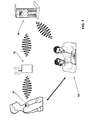
- the exemplary system for patient monitoring in FIG. 1 shows a patient with an implantable medical device 10 in the form of a pacemaker.
- This has a telemetry unit for wirelessly communicating with an external device 80, typically located near the patient.
- the external device 80 in turn can wirelessly or by way of a second interface, for example via telephone connections, to a central server 90 in a central service center communicate.
- a central service center Via the central service center, it is again possible to inform a doctor or a medical team 100 if, for example, the implantable medical device detects a critical condition and signals a central server 90 via the external device 80.
- the medical team 100 can then make direct contact with the patient.
- a typical implantable medical device is a pacemaker 10, as in US Pat FIG. 1 is shown. This is implanted under the skin of the patient and is located in a so-called pacemaker bag. After implantation of the pacemaker, the tissue forming the pacemaker pocket must heal. This can lead to local edematous water accumulation as part of an inflammatory reaction in the pacemaker pocket. However, in advanced stages of the inflammatory response, other diseased tissue changes, such as bagging of the pouch and, in the worst case, necrosis or disintegration of the tissue of the pacemaker pocket may occur so that the implant changes its original position. For this reason, it is important to recognize inflammatory reactions as early as possible. The investigation of these inflammatory reactions is nowadays usually carried out in the context of direct medical check-ups of a doctor.
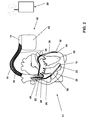
- FIG. 2 again shows the pacemaker 10 from the outside, and typical electrode lines 14, 16 and 30, via which the pacemaker 10 with electrodes 18, 20, 22, 24, 32, 34, 36, 38 and 40 is connected to the heart 12 of a patient and at least one of the four chambers of the heart 12, such as the right atrium 26 or the right ventricle 28, which are particularly important for the oxygenation of a patient, via these electrodes 18, 20, 22, 24, 32, 34, 36, 38, and can stimulate 40.
- the pacemaker 10 has a housing 40, usually made of a biocompatible material such as titanium, which includes electronic components. On the housing 42, a so-called header 11 is mounted, the contact sockets for connecting the electrode lines 14, 16 and 30 has.
- the header is often made of transparent plastic.
- FIG. 3 is a block diagram of the pacemaker 10 off FIG. 2 .
- the pacemaker 10 is not only a pure pacemaker, but simultaneously also a defibrillator, which can deliver defibrillation shocks to the heart via shock electrodes 36, 38, and 40.
- the pacemaker 10 is adapted to stimulate both the right ventricle 28 and the left ventricle 29 of the heart 12. For this purpose, the pacemaker 10 in FIG.
- ra-stim right-atrial stimulation unit
- ra-sens atrial sensing unit
- rv-stim right ventricular stimulation unit
- Iv-stim left ventricular pacing unit
- Ivsens left ventricle sensing unit
- a right ventricular shock unit 62 and a left ventricular shock unit 64 are provided, which are respectively connected to corresponding terminals for the connection of the corresponding electrode lines.
- a central control unit CTRL 54 which is connected on the one hand to a memory unit MEM 56 and on the other hand to a telemetry unit TEL 58.
- the control unit CTRL 54 is connected to a series of sensors with which parameters can be determined which give an indication of the state of health of the body tissue surrounding the pacemaker 10.
- a sensor is a position sensor 60 that is capable of detecting the direction of gravity with respect to the pacemaker 10, for example, by means of piezoelectric elements. At the same time, the position sensor 60 can also detect changes in position and accelerations of the cardiac pacemaker 10 and thus also supply characteristic sensor output signals for the activity of the patient. These sensor output signals are supplied to the control unit CTRL 54 and processed in the manner described above.
- Another sensor is an impedance sensor 70, which has a constant current source 72, and a voltage measuring unit 74, which are both connected to an impedance measuring unit 76.
- the constant current source 72 generates pairwise constant current pulses with alternating polarity and emits them via two electrodes, one of which is formed by the housing 42 of the cardiac pacemaker itself and the second electrode 80 is arranged in isolation on the housing 42 of the pacemaker 10.
- the impedance measuring unit 76 is connected to the control unit 54 and supplies thereto a sensor output signal which reflects the impedance of the tissue surrounding the pacemaker 10. This impedance is the lower, the greater the proportion of tissue fluid in the body tissue surrounding the pacemaker 10. The evaluation of this impedance sensor output signal by the control unit 54 is carried out in the manner described above.
- the tissue fluid of the body tissue surrounding the pacemaker 10 can also be detected with an ultrasound sensor 82 which has an ultrasound transducer for this purpose - for example in the form of a piezoelectric element - which can emit and receive ultrasound signals.
- an ultrasound sensor 82 which has an ultrasound transducer for this purpose - for example in the form of a piezoelectric element - which can emit and receive ultrasound signals.
- a reoccurrence of free fluid or an increase in tissue fluid at the end of 7 days after implantation of the cardiac pacemaker 10 is an indicator of a disorder in the wound healing process. This can be detected by evaluating the respective sensor output signal of the impedance sensor 70 or the ultrasonic sensor 82 in the manner described above.
- Another sensor is a pH sensor 78 with which the pH of the body tissue surrounding the pacemaker 10 can be determined.
- This pH is between 7.0 and 8.0 for normal tissue.
- Sensor 78 may also be detected by control unit 54 and interpreted as indicative of inflammation of the body tissue.
- the telemetry unit 58 itself can be used to obtain an output signal characterizing the state of health of the body tissue surrounding the pacemaker 10 by determining the permittivity of the body tissue surrounding the pacemaker 10 with the aid of the high-frequency transmitter and receiver provided in the telemetry unit 58 becomes. This is already described at the beginning.
- a particularly important sensor is a temperature sensor 79 which senses the temperature of the body tissue surrounding the pacemaker 10. This temperature is in the order of 36.5 ° C in healthy people. Increasing this temperature permanently by more than 1 ° C, so over 37.5 ° C, this is an indication of an inflammatory process, unless the patient has fever, for example. Therefore, the sensor output signal of the temperature sensor 79 can be used in the manner described above for the detection of an inflammatory tissue condition.
- control unit 54 is designed not only to evaluate a single sensor output signal to determine the state of health of the body tissue, but to evaluate a plurality of sensor output signals in combination with one another.
- the control unit 54 detects inflamed body tissue that the sensor output signal of the temperature sensor 79 indicates a body temperature increased by at least 1 ° C for several hours, the sensor output signal of the tissue fluid sensor indicates an increased tissue fluid content of the body tissue surrounding the pacemaker 10 and the sensor output signal of the pH value. Sensor indicates a pH below 7.
- control unit 54 If the control unit 54 detects such a parameter constellation and thus detects a potentially pathological body tissue condition, it triggers the sending of a warning signal via the telemetry unit 58. This is ultimately delivered via the external device 80 to the central server 90.
- the central server 90 can forward a warning to a respective physician looking after the patient, for example by text message or e-mail.
- the pacemaker 10 a drug depot 83, in which an anti-inflammatory drug from the group of steroids such as Dexamethasone and / or prednisolone is located.
- the drug depot 83 is connected to the control unit 54 in such a way that, as a result of a corresponding control signal of the control unit 54, it delivers the medicament to the environment of the pacemaker 10.
- the control unit 54 outputs this control signal when, as described above, it has detected a diseased tissue condition.
Landscapes
- Health & Medical Sciences (AREA)
- Life Sciences & Earth Sciences (AREA)
- Engineering & Computer Science (AREA)
- Heart & Thoracic Surgery (AREA)
- Molecular Biology (AREA)
- Biophysics (AREA)
- Pathology (AREA)
- Biomedical Technology (AREA)
- Veterinary Medicine (AREA)
- Medical Informatics (AREA)
- Physics & Mathematics (AREA)
- Surgery (AREA)
- Animal Behavior & Ethology (AREA)
- General Health & Medical Sciences (AREA)
- Public Health (AREA)
- Computer Networks & Wireless Communication (AREA)
- Measuring And Recording Apparatus For Diagnosis (AREA)
- Electrotherapy Devices (AREA)
Applications Claiming Priority (1)
| Application Number | Priority Date | Filing Date | Title |
|---|---|---|---|
| DE102007034042A DE102007034042A1 (de) | 2007-07-20 | 2007-07-20 | Implantierbares medizinisches Gerät |
Publications (1)
| Publication Number | Publication Date |
|---|---|
| EP2016892A1 true EP2016892A1 (fr) | 2009-01-21 |
Family
ID=39752381
Family Applications (1)
| Application Number | Title | Priority Date | Filing Date |
|---|---|---|---|
| EP08158972A Withdrawn EP2016892A1 (fr) | 2007-07-20 | 2008-06-25 | Appareil médical implantable |
Country Status (3)
| Country | Link |
|---|---|
| US (1) | US20090024054A1 (fr) |
| EP (1) | EP2016892A1 (fr) |
| DE (1) | DE102007034042A1 (fr) |
Cited By (2)
| Publication number | Priority date | Publication date | Assignee | Title |
|---|---|---|---|---|
| CN105962969A (zh) * | 2015-03-13 | 2016-09-28 | 百多力欧洲股份两合公司 | 错位感应器 |
| EP3815649A1 (fr) * | 2019-10-28 | 2021-05-05 | Klinikum rechts der Isar der Technischen Universität München | Espaceur endoprothétique de théragnostic |
Families Citing this family (15)
| Publication number | Priority date | Publication date | Assignee | Title |
|---|---|---|---|---|
| US8882759B2 (en) * | 2009-12-18 | 2014-11-11 | Covidien Lp | Microwave ablation system with dielectric temperature probe |
| US20120165636A1 (en) * | 2010-07-22 | 2012-06-28 | Feldman Benjamin J | Systems and Methods for Improved In Vivo Analyte Sensor Function |
| US9480807B2 (en) | 2013-10-02 | 2016-11-01 | Elwha Llc | Device and method for detection and treatment of ventilator associated pneumonia in a mammalian subject |
| US20150090269A1 (en) * | 2013-10-02 | 2015-04-02 | Elwha Llc | Device and Method for Detection and Treatment of Ventilator Associated Pneumonia in a Mammalian Subject |
| CN106667437B (zh) * | 2016-12-22 | 2023-05-26 | 北京品驰医疗设备有限公司 | 一种预测植入式医疗设备手术后并发症的系统 |
| CN106725434A (zh) * | 2016-12-30 | 2017-05-31 | 北京品驰医疗设备有限公司 | 一种基于温度反馈的远程监测定位系统 |
| CN106510645A (zh) * | 2016-12-31 | 2017-03-22 | 北京品驰医疗设备有限公司 | 一种快速闭环充电的组织破溃监测系统 |
| CN106667440B (zh) * | 2016-12-31 | 2023-05-30 | 北京品驰医疗设备有限公司 | 一种充电的组织病变检测系统 |
| CN106621045B (zh) * | 2016-12-31 | 2023-07-04 | 北京品驰医疗设备有限公司 | 一种充电控制的组织病变检测系统 |
| CN106510768B (zh) * | 2016-12-31 | 2023-05-30 | 北京品驰医疗设备有限公司 | 一种温控充电的组织病变检测系统 |
| DE102018204949A1 (de) | 2018-03-30 | 2019-10-02 | Bernhard Clasbrummel | Implantat und Verfahren zur Diagnose und/oder Behandlung entzündlicher Gewebezustände |
| AU2020204711A1 (en) | 2019-01-04 | 2021-07-08 | Iota Biosciences, Inc. | Power controls for an implantable device powered using ultrasonic waves |
| CN113226455A (zh) * | 2019-01-04 | 2021-08-06 | 艾奧塔生物科技公司 | 用于操作可植入设备的基于超声的协议 |
| US11896403B2 (en) | 2020-01-24 | 2024-02-13 | Medtronic, Inc. | Implantable medical device using temperature sensor to determine infection status of patient |
| CN113729623B (zh) * | 2020-05-30 | 2023-03-03 | 深圳硅基传感科技有限公司 | 生理参数监测仪的批量植入装置 |
Citations (5)
| Publication number | Priority date | Publication date | Assignee | Title |
|---|---|---|---|---|
| WO2000059376A1 (fr) | 1999-04-07 | 2000-10-12 | Endonetics, Inc. | Sonde de surveillance implantable |
| US20050012610A1 (en) | 2003-07-11 | 2005-01-20 | Yen-Shuo Liao | Joint endoprosthesis with ambient condition sensing |
| EP1611835A2 (fr) | 2004-06-29 | 2006-01-04 | Depuy Products, Inc. | Système de communication bidirectionelle avec un dispositif médical implantable |
| EP1665983A2 (fr) | 2004-12-02 | 2006-06-07 | BIOTRONIK CRM Patent AG | Appareil de détermination de l'impédance du thorax |
| US20060149330A1 (en) | 2004-12-30 | 2006-07-06 | Brian Mann | Digitally controlled cardiac rhythm management |
Family Cites Families (13)
| Publication number | Priority date | Publication date | Assignee | Title |
|---|---|---|---|---|
| DE3601730A1 (de) * | 1985-01-23 | 1986-09-11 | Horst 2000 Hamburg Mau | Verfahren und vorrichtung zur erkennung und regulierung von koerperfluessigkeitswerten |
| DE19638585A1 (de) * | 1996-09-20 | 1998-03-26 | Biotronik Mess & Therapieg | Vorrichtung zur Rejektionsdiagnostik nach Organtransplantationen |
| US5957861A (en) * | 1997-01-31 | 1999-09-28 | Medtronic, Inc. | Impedance monitor for discerning edema through evaluation of respiratory rate |
| US6117643A (en) * | 1997-11-25 | 2000-09-12 | Ut Battelle, Llc | Bioluminescent bioreporter integrated circuit |
| US6045513A (en) * | 1998-05-13 | 2000-04-04 | Medtronic, Inc. | Implantable medical device for tracking patient functional status |
| US6092530A (en) * | 1999-03-24 | 2000-07-25 | The B.F. Goodrich Company | Remotely interrogated implant device with sensor for detecting accretion of biological matter |
| DE10103503A1 (de) * | 2001-01-26 | 2002-08-14 | Fraunhofer Ges Forschung | Endoluminales expandierbares Implantat mit integrierter Sensorik |
| US6963772B2 (en) * | 2002-04-17 | 2005-11-08 | The Board Of Trustees Of The Leland Stanford Junior University | User-retainable temperature and impedance monitoring methods and devices |
| US20030229274A1 (en) * | 2002-06-07 | 2003-12-11 | Barnes-Jewish Hospital | Electromyograph having telemetry |
| ES2237317B1 (es) * | 2003-11-07 | 2006-11-01 | Universitat Politecnica De Catalunya | Sistema multiparametrico para el diagnostico de rechazo post-trasplante e inflamacion basado en la temperatura y la impedancia electrica tisular. |
| JP4874970B2 (ja) * | 2004-06-07 | 2012-02-15 | ジンテス ゲゼルシャフト ミット ベシュレンクテル ハフツング | センサ付き整形外科用インプラント |
| WO2008017042A1 (fr) * | 2006-08-03 | 2008-02-07 | Microchips, Inc. | dispositifs et procédés biodétecteurs cardiaques |
| US7604629B2 (en) * | 2007-04-19 | 2009-10-20 | Medtronic Inc. | Multi-parameter infection monitoring |
-
2007
- 2007-07-20 DE DE102007034042A patent/DE102007034042A1/de not_active Withdrawn
-
2008
- 2008-06-25 EP EP08158972A patent/EP2016892A1/fr not_active Withdrawn
- 2008-07-10 US US12/170,868 patent/US20090024054A1/en not_active Abandoned
Patent Citations (5)
| Publication number | Priority date | Publication date | Assignee | Title |
|---|---|---|---|---|
| WO2000059376A1 (fr) | 1999-04-07 | 2000-10-12 | Endonetics, Inc. | Sonde de surveillance implantable |
| US20050012610A1 (en) | 2003-07-11 | 2005-01-20 | Yen-Shuo Liao | Joint endoprosthesis with ambient condition sensing |
| EP1611835A2 (fr) | 2004-06-29 | 2006-01-04 | Depuy Products, Inc. | Système de communication bidirectionelle avec un dispositif médical implantable |
| EP1665983A2 (fr) | 2004-12-02 | 2006-06-07 | BIOTRONIK CRM Patent AG | Appareil de détermination de l'impédance du thorax |
| US20060149330A1 (en) | 2004-12-30 | 2006-07-06 | Brian Mann | Digitally controlled cardiac rhythm management |
Cited By (3)
| Publication number | Priority date | Publication date | Assignee | Title |
|---|---|---|---|---|
| CN105962969A (zh) * | 2015-03-13 | 2016-09-28 | 百多力欧洲股份两合公司 | 错位感应器 |
| EP3815649A1 (fr) * | 2019-10-28 | 2021-05-05 | Klinikum rechts der Isar der Technischen Universität München | Espaceur endoprothétique de théragnostic |
| WO2021083963A1 (fr) * | 2019-10-28 | 2021-05-06 | Klinikum Rechts Der Isar Der Technischen Universität München | Espaceur endoprothétique théragnostique |
Also Published As
| Publication number | Publication date |
|---|---|
| US20090024054A1 (en) | 2009-01-22 |
| DE102007034042A1 (de) | 2009-01-22 |
Similar Documents
| Publication | Publication Date | Title |
|---|---|---|
| EP2016892A1 (fr) | Appareil médical implantable | |
| DE60110024T2 (de) | Implantierbarer telemetrischer medizinischer Sensor | |
| DE60012905T2 (de) | Peripheres speicherpflaster und zugriffsverfahren zur verwendung mit einer implantierbaren medizinischen vorrichtung | |
| EP1586348B1 (fr) | Dispositif d'électrothérapie | |
| DE69918071T2 (de) | System zur Ableitung relativer physiologischer Signale | |
| DE68922362T2 (de) | Körperleitungspfad in einem Kommunikationssystem einer medizinischen Vorrichtung. | |
| DE69331961T2 (de) | Frequenzadaptiver Herzschrittmacher gesteuert mittels unipolar gemessener Impedanz | |
| DE60223146T2 (de) | Automatische erkennung und konfiguration implantierbarer medizinischer leitungen | |
| EP1665983B1 (fr) | Appareil de détermination de l'impédance du thorax | |
| DE69929448T2 (de) | Implantierbarer sensor mit drahtloser kommunikation | |
| DE60106645T2 (de) | Apparat zur messung des mittleren blutdruckes in der lungenarterie von der herzkammer aus mit einem mobilen überwachungsgerät | |
| DE69417609T2 (de) | Räumlich getrennte Kontrollvorrichtung für einen implantierbaren Stimulator für das Gewebewachstum | |
| DE60129101T2 (de) | Telemetrisches medizinisches System | |
| DE60035719T2 (de) | Vorrichtung zum Überwachen der Herzfrequenz und einer abnormalen Beatmung | |
| DE69119242T2 (de) | Medizinisches stimulationsgerät mit einer operationverstärker-ausgangschaltung | |
| EP1955650B1 (fr) | Appareil médical implantable | |
| DE102008010651B4 (de) | System und Verfahren zur Auswertung eines Impedanzverlaufs | |
| DE69901296T2 (de) | Implantat enthaltend ein piezoelektrisches material | |
| EP2502646B1 (fr) | Appareil implantable | |
| EP2364643B1 (fr) | Implant électromédical et système de surveillance doté de cet implant électromédical | |
| DE602007000008T2 (de) | Aktives medizinisches Implantat zur Herzstimulation, Resynchronisation, Kardioversion und/oder Defibrillation, das Mittel zum Erfassen eines Sondenbruchs umfasst | |
| DE69725330T2 (de) | Herzschrittmacher | |
| EP3025757B1 (fr) | Appareil actif implantable pour mrt | |
| DE602005000554T2 (de) | Implantable cardiac stimulation device with automatic detection of the installation of a probe and of the implantation of the housing | |
| EP2422843B1 (fr) | Appareil de thérapie électronique implantable |
Legal Events
| Date | Code | Title | Description |
|---|---|---|---|
| PUAI | Public reference made under article 153(3) epc to a published international application that has entered the european phase |
Free format text: ORIGINAL CODE: 0009012 |
|
| AK | Designated contracting states |
Kind code of ref document: A1 Designated state(s): AT BE BG CH CY CZ DE DK EE ES FI FR GB GR HR HU IE IS IT LI LT LU LV MC MT NL NO PL PT RO SE SI SK TR |
|
| AX | Request for extension of the european patent |
Extension state: AL BA MK RS |
|
| 17P | Request for examination filed |
Effective date: 20090710 |
|
| 17Q | First examination report despatched |
Effective date: 20090807 |
|
| AKX | Designation fees paid |
Designated state(s): AT BE BG CH CY CZ DE DK EE ES FI FR GB GR HR HU IE IS IT LI LT LU LV MC MT NL NO PL PT RO SE SI SK TR |
|
| STAA | Information on the status of an ep patent application or granted ep patent |
Free format text: STATUS: THE APPLICATION IS DEEMED TO BE WITHDRAWN |
|
| 18D | Application deemed to be withdrawn |
Effective date: 20120803 |