EP1669526A2 - Serrure de véhicule automobile - Google Patents
Serrure de véhicule automobile Download PDFInfo
- Publication number
- EP1669526A2 EP1669526A2 EP05024171A EP05024171A EP1669526A2 EP 1669526 A2 EP1669526 A2 EP 1669526A2 EP 05024171 A EP05024171 A EP 05024171A EP 05024171 A EP05024171 A EP 05024171A EP 1669526 A2 EP1669526 A2 EP 1669526A2
- Authority
- EP
- European Patent Office
- Prior art keywords
- pawl
- storage lever
- lever
- latch
- engagement
- Prior art date
- Legal status (The legal status is an assumption and is not a legal conclusion. Google has not performed a legal analysis and makes no representation as to the accuracy of the status listed.)
- Granted
Links
- 230000003213 activating effect Effects 0.000 claims 1
- 238000002347 injection Methods 0.000 claims 1
- 239000007924 injection Substances 0.000 claims 1
- 238000000034 method Methods 0.000 description 15
- 230000008569 process Effects 0.000 description 15
- 230000004913 activation Effects 0.000 description 14
- 230000001133 acceleration Effects 0.000 description 10
- 230000006870 function Effects 0.000 description 8
- 230000000295 complement effect Effects 0.000 description 5
- 230000007257 malfunction Effects 0.000 description 5
- 230000008878 coupling Effects 0.000 description 3
- 238000010168 coupling process Methods 0.000 description 3
- 238000005859 coupling reaction Methods 0.000 description 3
- 238000004519 manufacturing process Methods 0.000 description 3
- 230000003111 delayed effect Effects 0.000 description 1
- 238000005516 engineering process Methods 0.000 description 1
- 230000002093 peripheral effect Effects 0.000 description 1
- 230000009467 reduction Effects 0.000 description 1
Images


Classifications
-
- E—FIXED CONSTRUCTIONS
- E05—LOCKS; KEYS; WINDOW OR DOOR FITTINGS; SAFES
- E05B—LOCKS; ACCESSORIES THEREFOR; HANDCUFFS
- E05B81/00—Power-actuated vehicle locks
- E05B81/12—Power-actuated vehicle locks characterised by the function or purpose of the powered actuators
- E05B81/14—Power-actuated vehicle locks characterised by the function or purpose of the powered actuators operating on bolt detents, e.g. for unlatching the bolt
- E05B81/15—Power-actuated vehicle locks characterised by the function or purpose of the powered actuators operating on bolt detents, e.g. for unlatching the bolt with means preventing the detent to return to its latching position before the bolt has moved to the unlatched position
Definitions
- the invention relates to a motor vehicle lock having the features of the preamble of claim 1.
- the motor vehicle lock in question in the present case comprises all types of motor vehicle locks, for example side door locks, hood locks, rear door locks and, in particular, tailgate locks.
- the well-known motor vehicle lock (DE 101 58 733 A1), from which the invention proceeds, is equipped with the usual closing elements latch and pawl, the latch in one embodiment in an open position, a main closed position and a Vorsch practitioner can be brought.
- the pawl can be brought and biased into an incidence position in which it holds the latch in the main closed position.
- the latch has a main catch and a pre-rest.
- the pawl In order to release the latch, the pawl can be lifted in a Aushebegna.
- the latch located in the main closed position and in the prelocking position is in holding engagement with a normally arranged on the bodywork of the motor vehicle closing wedge.
- a storage lever which can be brought and biased into an incidence position in which he holds the pawl in its Aushebegna.
- the storage lever is also brought against its bias in a release position, whereby the pawl is releasable again. If the pawl is now dug out of its sinking position when the lock catch is in the main closing position, the storage lever falls into its sinking position and holds the pawl in its release position until the latch reaches its open position. This ensures that in the event of any delay in the opening of the motor vehicle door or flap, the repeated engagement of the pawl and thus an undesired interruption of the opening process is avoided.
- Such a delay of the opening of the vehicle door or flap may be caused, for example, by frozen door seals or the like.
- Another example is a snow covered tailgate, where the weight of the snow is opening the flap is delayed or even prevented.
- the above storage lever is therefore also called “snow load lever”. Accordingly, the described function of holding the pawl in the Aushebehyroid is also called “snow load function”.
- the snow load function guarantees optimum comfort during the opening process, it often causes malfunctions during the closing process.
- An example of this is the unintentional collapse of the memory lever during powerful slamming the vehicle door or flap.
- the locking wedge engages with the latch and brings them from the open position on the prelocking in the main closed position.
- the pawl slides with a latching lug along the back of the latch and initially falls to the latch in the direction of their Einfall ein.
- the locking lug of the pawl then slides along the latch along and is raised against its bias again until it finally falls into the main catch in their incident position.
- the acceleration ramp can be flattened, which possibly leads to a reduction in the depth of the main load.
- the pawl is here in return to provide a higher bias. This is disadvantageous in that the falling back of the pawl is connected to the back of the latch after opening the vehicle door or door with a higher noise. This is seen by the operator of the motor vehicle as a loss of comfort. Furthermore, the lifting of the pawl with a larger Connected force, which is disadvantageous both manual and motorized lifting.
- the storage lever occurs only when the pawl has been excavated particularly far. This reduces the likelihood of accidental collapse of the storage lever during the closing process. However, even with this variant, an increased noise level is expected when the pawl falls back.
- the invention is based on the problem, the known motor vehicle lock in such a way and further develop that the risk of caused by the storage lever malfunction of the motor vehicle lock is reduced with little effort and no loss of comfort.
- the opening process is characterized in that the pawl is initially in its position of incidence. This makes use of the proposed solution.
- the excavated storage lever is in fact activated by the adjustment of the pawl in its Einfallwolf, with only the memory lever located in the activated state can fall by its bias in its incident position.
- the latch is preferably additionally brought into a prelocking position, in which it is held by the located in a Vorschstedence position pawl. If the pre-closing incidence position is identical to the (main-closing) incidence position, there is theoretically the danger of activation of the storage lever when the locking lug of the pawl during the closing process, the pre-rest of the latch happens and falls accordingly. The probability of such - unwanted - activation of the memory lever is, however, only small, since the locking lug of the pawl during closing usually in a range between the pre-rest and the main load - acceleration ramp - impinges on the latch and the pre-closing position in the conventional closing operation usually not achieved.
- the depth of incidence of the pre-closing incidence position is less than the depth of incidence of the (main closing) incidence position. Since activation of the storage lever only by an adjustment of the pawl in the (main closing) Einfall ein is possible, an unwanted activation of the storage lever during the closing process is now completely excluded.
- the preferred embodiment according to claim 6 leads to a compact and overall cost to manufacture variant.
- the embodiment proposed according to claim 7 has manufacturing advantages.
- an opening auxiliary drive is provided, through which the pawl is raised by a motor.
- the opening auxiliary drive can be designed comparatively weak here, as can be dispensed with the proposed solution to a particularly high bias of the pawl to avoid the unwanted incidence of the storage lever during the closing process.
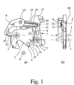
- the motor vehicle lock shown is equipped with the closing elements latch 1 and pawl 2, wherein the latch 1 is pivotable about a latch axis 3 and in an open position (Fig. 1), a main closing position (Fig. 2) and in a Vorsch practitioner not shown brought.
- the latch 1 has a main catch 4 and a pre-rest 5.
- the latch 1 When in the main locking position and in the prelocking located latch 1, the latch 1 is in holding engagement with a usually arranged on the body of the motor vehicle locking wedge 6.
- the latch 1 is preferably biased in its open position.
- the pawl 2 is pivotable about a pawl axis 7 and brought into an incidence position and biased in which it holds the latch 1 in the main closed position.
- the pawl 2 is equipped with a locking lug 8.
- the bias of the latch 1 on the one hand and the pawl 2 on the other hand can be preferably by a leg spring, not shown o. The like. Realize.
- the pawl 2 can be brought against its bias in a Aushebegna (Fig. 3), whereby the latch 1 is releasable.
- the latch 1 can then pivot by their bias and by acting on the latch bolt 1 by the closing wedge 6 in its open position. This will be referred to as an opening operation in the following.
- the pivoting of the latch 1 from the open position to the main closing position with a subsequent collapse of the pawl 2 in its incident position is hereinafter referred to as the closing operation.
- the motor vehicle lock is further equipped with a storage lever 9 which is pivotable about a memory lever axis 10 and in an incident position (Fig. 3) and biased in which he holds the pawl 2 in its Aushebewolf.
- the bias of the storage lever 9 is realized by a leg spring 11 shown in FIG.
- the storage lever 9 is further brought against its bias in a release position, whereby the pawl 2 is releasable and can pivot in the direction of their Einfall ein.
- the excavated storage lever 9 can be activated by the adjustment of the pawl 2 in its incident position and that only the memory lever 9 located in the activated state falls when lifting the pawl 2 by its bias in its incident position.
- a special coupling between the pawl 2 and the storage lever 9 is provided.
- the pawl 2 is preferably provided with a contour 12, with which a arranged on the storage lever 9 engaging element 13 corresponds.
- the pawl 2 blocked via the contour 12 and the corresponding engaging element 13, a first adjustment of the excavated storage lever 9 until the pawl 2 reaches its position of incidence for activation of the storage lever 9. It should be noted that the removal of this blockage, ie the activation of the storage lever 9, here only a necessary, but not yet sufficient condition for the collapse of the storage lever 9 represents. Only the subsequent lifting of the pawl 2 leads namely to the collapse of the storage lever 9 in the position of incidence.
- the contour 12 and the engagement member 13 may each be arranged alternately on the pawl 2 or the storage lever 9.
- the pawl 2 can be brought into a pre-closing incidence position, not shown, in which it holds the latch 1 in the prelocking position.
- a pre-closing incidence position not shown, in which it holds the latch 1 in the prelocking position.
- This area is referred to below as acceleration ramp 15, since the pawl 2 slides along in the further pivoting of the latch 1 on the acceleration ramp 15 and is thereby accelerated in the direction of their Aushebewolf.
- this acceleration can cause the pawl 2 to reach its picking position or even an overstroke position. Since, in this state, the storage lever 9 has not been activated according to the proposal, this acceleration of the pawl 2 does not cause the unintentional collapse of the storage lever 9.
- the locking lug 8 passes on further pivoting of the latch 1, the main catch 4 and falls into their position of incidence (Fig. 2).
- the pre-closing incidence position is identical to the (main-closing) incidence position, so that during slow closing movement the incidence of the pawl 2 in its position of incidence on the pre-restraint 5 can not be completely excluded.
- the unwanted activation of the storage lever 9 would be the result.
- the depth of incidence of the pre-closing incidence position is less than the depth of incidence of the (main) recessed position. Then an activation of the storage lever 9 also certainly does not occur when reaching the pre-rest 5.
- incident position basically meant the (main closing) incidence position of the pawl 2.
- the storage lever 9 is initially held by the latch 1 in a raised position. Strictly speaking, this is a Uberhub ein assigned to the Aushebeloid.
- the latch 1 pivots in the direction of its main closing position and comes out of engagement with the storage lever 9, wherein the storage lever 9 comes into contact with the contour 12 by its bias with the engagement member 13.
- the storage lever 9 is then held by the contour 12 of the pawl 2. Now, if the latch 1 reaches its main closed position (or one of the main closing position associated overstroke position), the pawl falls 2 in the incidence position shown in Fig. 2 a. It can be seen from the combination of FIGS.
- the contour 12 first slides along the engagement element 13 until the contour 12 finally comes out of engagement with the engagement element 13. Then pass through the bias of the storage lever 9, the engagement element 13 and the contour 12 each other and the storage lever 9 comes into contact with a contact surface 16 of the pawl 2 - the storage lever 9 is activated. In a subsequent lifting of the pawl 2, the storage lever 9 finally passes the contact surface 16 and falls into its Einfallwolf. This is shown in FIG. In this incident position, the storage lever 9 is engaged with a further contact surface 17 of the pawl 2.
- the above contour 12 is aligned substantially circular arc around the pawl axis 7.
- a corresponding orientation of the contour is meant in befindlichem in the raising position memory lever 9.
- the contour 12 can also be designed straight, possibly even have kinks.
- the configuration of the contour is also advantageous insofar as it extends far enough - in Fig. 1a) to the left - to exclude the unwanted activation of the storage lever 9 even with a particularly wide lifting of the pawl 2.
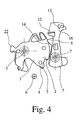
- the contour 12 is formed as a web with a height extension in the direction of the pawl axis 7. This can be seen in FIGS. 1 to 3 in the illustration b). Fig. 4, the shape of the web formed as a contour 12 can be particularly good.
- the contour 12 may be designed as a slot in a wall segment, as an edge or as a shoulder.
- contour 12 and engagement element 13 makes it necessary that when the storage lever 9 is raised from the incidence position, the engagement element 13 changes from one side of the contour 12 to the other side of the contour 12. At the same time, the contour 12 must prevent a deferral of the storage lever 9 in this state, since the pawl 2 is not here in the lowered position and activation of the storage lever 9 is not desired.
- the storage lever 9 When lifting the storage lever 9, a passing over of the contour 12 and a subsequent engagement of the storage lever 9 behind the contour 12 is provided in a preferred embodiment.
- the storage lever 9 is designed at least partially elastic. In principle, however, it may also be provided that, alternatively or additionally, the pawl 2 is designed to be elastic according to the part.
- locking of the storage lever 9 is not necessarily meant a frictional connection between the engagement member 13 and the contour 12. It is essential here only that after returning the contour 12, a provision of the storage lever 9 is prevented by the contour 12.
- This resilient arrangement of the engagement element 13 can be ensured, for example, by a separate spring element.
- the engagement member 13 is disposed on a resilient tongue 18 of the storage lever 9 or, in complementary arrangement, the pawl 2, wherein in a particularly preferred embodiment of the storage lever 9 or, in a complementary arrangement, the pawl 2, designed as a plastic part and in particular as a one-piece injection-molded part.
- both the pawl 2 and the storage lever 9 can be made as a plastic part and in particular as a one-piece injection-molded part.
- FIGS. 1 to 3 An above-described, resilient tongue 18 on the storage lever 9 can be seen in FIGS. 1 to 3.
- the storage lever 9 is designed as a one-piece injection-molded part, wherein the tongue 18 is arranged with a peripheral edge 19 within the storage lever 9.
- the engagement element 13 has a first engagement surface 20 which can be brought into engagement with the contour 12 when the storage lever 9 is raised.
- the engagement element 13 also has a second engagement surface 21 which comes into engagement with the contour 12 during the opening movement of the lock catch 1, and thus when the contour 12 is passed over.
- the first engagement surface 20 extends substantially in the direction of the memory lever axis 10
- the second engagement surface 21 extends substantially obliquely to the direction of the memory lever axis 10.
- the engagement element 13 is thus designed in the manner of a ratchet. Depending on the application, other configurations and arrangements of the engagement member 13 may be provided.
- a guide surface 22 is provided on the latch 1 and a corresponding guide surface 23 is provided on the storage lever 9.
- a guide surface 22 is provided on the latch 1 and a corresponding guide surface 23 is provided on the storage lever 9.
- an unillustrated opening auxiliary drive is provided, through which the pawl 2 can be raised by a motor.
Landscapes
- Lock And Its Accessories (AREA)
- Vehicle Body Suspensions (AREA)
Applications Claiming Priority (1)
| Application Number | Priority Date | Filing Date | Title |
|---|---|---|---|
| DE202004019060U DE202004019060U1 (de) | 2004-12-08 | 2004-12-08 | Kraftfahrzeugschloß |
Publications (3)
| Publication Number | Publication Date |
|---|---|
| EP1669526A2 true EP1669526A2 (fr) | 2006-06-14 |
| EP1669526A3 EP1669526A3 (fr) | 2006-07-26 |
| EP1669526B1 EP1669526B1 (fr) | 2009-04-15 |
Family
ID=36102983
Family Applications (1)
| Application Number | Title | Priority Date | Filing Date |
|---|---|---|---|
| EP05024171A Expired - Lifetime EP1669526B1 (fr) | 2004-12-08 | 2005-11-05 | Serrure de véhicule automobile |
Country Status (4)
| Country | Link |
|---|---|
| EP (1) | EP1669526B1 (fr) |
| AT (1) | ATE428835T1 (fr) |
| DE (2) | DE202004019060U1 (fr) |
| ES (1) | ES2323076T3 (fr) |
Cited By (6)
| Publication number | Priority date | Publication date | Assignee | Title |
|---|---|---|---|---|
| DE102008046931A1 (de) * | 2008-09-12 | 2010-03-18 | Kiekert Ag | Kraftfahrzeugschloss mit Geräuschminderung beim Schließvorgang |
| DE102009042061A1 (de) * | 2009-09-17 | 2011-04-21 | GM Global Technology Operations, Inc., Detroit | Sicherheitsrastschloss eines Kraftfahrzeuges, Kraftfahrzeug |
| ITAN20100156A1 (it) * | 2010-09-27 | 2012-03-28 | So Ge Mi Spa | Serratura perfezionata per il portellone posteriore delle automobili. |
| EP2476830A3 (fr) * | 2011-01-14 | 2015-10-28 | Magna Closures SpA | Loquet de porte avec ouverture de fonction de mémoire |
| WO2018115949A1 (fr) * | 2016-12-19 | 2018-06-28 | Kiekert Aktiengesellschaft | Verrou de portière de véhicule automobile |
| US20230349203A1 (en) * | 2020-09-15 | 2023-11-02 | Kiekert Ag | Motor vehicle lock, in particular motor vehicle door lock |
Families Citing this family (3)
| Publication number | Priority date | Publication date | Assignee | Title |
|---|---|---|---|---|
| DE102008061524A1 (de) * | 2008-12-10 | 2010-06-17 | Kiekert Ag | Mehrklinken-Gesperre mit Rasthaken |
| DE102012017677A1 (de) | 2012-09-07 | 2014-03-13 | Kiekert Aktiengesellschaft | Kraftfahrzeugtürschloss |
| DE102012024689A1 (de) | 2012-12-18 | 2014-06-18 | BROSE SCHLIEßSYSTEME GMBH & CO. KG | Kraftfahrzeugschloss |
Citations (2)
| Publication number | Priority date | Publication date | Assignee | Title |
|---|---|---|---|---|
| DE19617428C2 (de) | 1996-05-01 | 1998-06-10 | Kiekert Ag | Kraftfahrzeug-Türverschluß mit elektrischem Türschloß und elektrische Zuziehhilfe für die zugeordnete Kraftfahrzeugtür |
| DE10158733A1 (de) | 2001-01-30 | 2003-02-20 | Bosch Gmbh Robert | Kraftfahrzeug-Klappenschloss-Anordnung |
Family Cites Families (5)
| Publication number | Priority date | Publication date | Assignee | Title |
|---|---|---|---|---|
| DE4033271C2 (de) * | 1990-07-25 | 1997-11-20 | Kiekert Ag | Kraftfahrzeug-Türverschluß mit Speichereinrichtung für eine Öffnungsbedienung |
| DE19520359A1 (de) * | 1995-06-07 | 1996-12-12 | Bocklenberg & Motte Bomoro | Kraftfahrzeug-Hauben- oder Türverschluß |
| FR2804713A1 (fr) * | 2000-02-08 | 2001-08-10 | Valeo Securite Habitacle | Serrure electrique a contacteur de serrure ouverte et systeme d'une gache mobile et d'une telle serrure |
| DE10208813B4 (de) * | 2002-03-01 | 2004-06-17 | R-R-R Transportgeräte-Fabrik GmbH | Hubroller |
| EP1457625A3 (fr) * | 2003-03-08 | 2008-08-27 | Brose Schliesssysteme GmbH & Co. KG | Serrure pour véhicule à ouverture assistée électriquement |
-
2004
- 2004-12-08 DE DE202004019060U patent/DE202004019060U1/de not_active Expired - Lifetime
-
2005
- 2005-11-05 ES ES05024171T patent/ES2323076T3/es not_active Expired - Lifetime
- 2005-11-05 DE DE502005007083T patent/DE502005007083D1/de not_active Expired - Lifetime
- 2005-11-05 EP EP05024171A patent/EP1669526B1/fr not_active Expired - Lifetime
- 2005-11-05 AT AT05024171T patent/ATE428835T1/de not_active IP Right Cessation
Patent Citations (2)
| Publication number | Priority date | Publication date | Assignee | Title |
|---|---|---|---|---|
| DE19617428C2 (de) | 1996-05-01 | 1998-06-10 | Kiekert Ag | Kraftfahrzeug-Türverschluß mit elektrischem Türschloß und elektrische Zuziehhilfe für die zugeordnete Kraftfahrzeugtür |
| DE10158733A1 (de) | 2001-01-30 | 2003-02-20 | Bosch Gmbh Robert | Kraftfahrzeug-Klappenschloss-Anordnung |
Cited By (11)
| Publication number | Priority date | Publication date | Assignee | Title |
|---|---|---|---|---|
| DE102008046931A1 (de) * | 2008-09-12 | 2010-03-18 | Kiekert Ag | Kraftfahrzeugschloss mit Geräuschminderung beim Schließvorgang |
| DE102008046931B4 (de) | 2008-09-12 | 2022-12-29 | Kiekert Aktiengesellschaft | Kraftfahrzeugschloss mit Geräuschminderung beim Schließvorgang |
| DE102009042061A1 (de) * | 2009-09-17 | 2011-04-21 | GM Global Technology Operations, Inc., Detroit | Sicherheitsrastschloss eines Kraftfahrzeuges, Kraftfahrzeug |
| ITAN20100156A1 (it) * | 2010-09-27 | 2012-03-28 | So Ge Mi Spa | Serratura perfezionata per il portellone posteriore delle automobili. |
| EP2434077A1 (fr) * | 2010-09-27 | 2012-03-28 | SO.GE.MI. S.p.A. | Verrou amélioré pour porte arrière de véhicule |
| EP2476830A3 (fr) * | 2011-01-14 | 2015-10-28 | Magna Closures SpA | Loquet de porte avec ouverture de fonction de mémoire |
| US10352070B2 (en) | 2011-01-14 | 2019-07-16 | Magna Closures Inc. | Door latch with opening memory feature |
| WO2018115949A1 (fr) * | 2016-12-19 | 2018-06-28 | Kiekert Aktiengesellschaft | Verrou de portière de véhicule automobile |
| US10865589B2 (en) | 2016-12-19 | 2020-12-15 | Kiekert Ag | Motor vehicle door latch |
| US20230349203A1 (en) * | 2020-09-15 | 2023-11-02 | Kiekert Ag | Motor vehicle lock, in particular motor vehicle door lock |
| US12338664B2 (en) * | 2020-09-15 | 2025-06-24 | Kiekert Ag | Motor vehicle lock, in particular motor vehicle door lock |
Also Published As
| Publication number | Publication date |
|---|---|
| ATE428835T1 (de) | 2009-05-15 |
| EP1669526B1 (fr) | 2009-04-15 |
| EP1669526A3 (fr) | 2006-07-26 |
| DE202004019060U1 (de) | 2006-04-20 |
| DE502005007083D1 (de) | 2009-05-28 |
| ES2323076T3 (es) | 2009-07-06 |
Similar Documents
| Publication | Publication Date | Title |
|---|---|---|
| EP2304139B1 (fr) | Serrure a levier de blocage et centre de gravite reequilibre | |
| EP2440730B1 (fr) | Serrure avec guidage forcé du cliquet | |
| DE10312304B4 (de) | Kraftffahrzeugschloß | |
| DE102016210596A1 (de) | Fahrzeug-Haubenverriegelung und Verfahren zum Entriegeln einer Fahrzeughaube | |
| DE102007003948A1 (de) | Schlosseinheit mit mehrteiliger Sperrklinke | |
| DE102009026921A1 (de) | Kraftfahrzeugschloss mit Zuziehhilfe | |
| EP0083752A2 (fr) | Boucle pour ceintures de sécurité | |
| DE102010049393A1 (de) | Kraftfahrzeugtürverschluss | |
| DE102013211050A1 (de) | Schloss für ein Kraftfahrzeug | |
| DE2034388A1 (de) | Schloß | |
| EP1632626B1 (fr) | Serrure pour véhicule automobile | |
| DE102019100169A1 (de) | Doppelzug-Hauben-Verriegelungsanordnung | |
| DE102019134659A1 (de) | Intelligente verriegelungsvorrichtung mit doppelklinken-verriegelungsmechanismus mit flexibler verbindung zu einem lösemechanismus | |
| DE102012203734A1 (de) | Schloss für eine Klappe oder Tür | |
| DE10361168B4 (de) | Kraftfahrzeugschloß, insbesondere für Hauben oder Klappen | |
| EP1669526B1 (fr) | Serrure de véhicule automobile | |
| DE102016224299A1 (de) | Verriegelung mit Zuschlag-Stoppmerkmal | |
| DE102009046880A1 (de) | Kraftfahrzeugschloss | |
| DE102017113880A1 (de) | Kraftfahrzeugschloss | |
| DE102009026919A1 (de) | Schloss mit steuerbarer Vorspannung | |
| DE102004032147A1 (de) | Schloss eines bewegbaren Elements einer Fahrzeugkarosserie | |
| EP3374582B1 (fr) | Dispositif de verrouillage d'un véhicule automobile | |
| EP1267023B1 (fr) | Dispositif de fermeture assisté pour une porte de véhicule | |
| DE102018128420A1 (de) | Kraftfahrzeugschloss | |
| DE3006151C2 (fr) |
Legal Events
| Date | Code | Title | Description |
|---|---|---|---|
| PUAI | Public reference made under article 153(3) epc to a published international application that has entered the european phase |
Free format text: ORIGINAL CODE: 0009012 |
|
| AK | Designated contracting states |
Kind code of ref document: A2 Designated state(s): AT BE BG CH CY CZ DE DK EE ES FI FR GB GR HU IE IS IT LI LT LU LV MC NL PL PT RO SE SI SK TR |
|
| AX | Request for extension of the european patent |
Extension state: AL BA HR MK YU |
|
| PUAL | Search report despatched |
Free format text: ORIGINAL CODE: 0009013 |
|
| AK | Designated contracting states |
Kind code of ref document: A3 Designated state(s): AT BE BG CH CY CZ DE DK EE ES FI FR GB GR HU IE IS IT LI LT LU LV MC NL PL PT RO SE SI SK TR |
|
| AX | Request for extension of the european patent |
Extension state: AL BA HR MK YU |
|
| 17P | Request for examination filed |
Effective date: 20070126 |
|
| AKX | Designation fees paid |
Designated state(s): AT BE BG CH CY CZ DE DK EE ES FI FR GB GR HU IE IS IT LI LT LU LV MC NL PL PT RO SE SI SK TR |
|
| 17Q | First examination report despatched |
Effective date: 20070327 |
|
| GRAP | Despatch of communication of intention to grant a patent |
Free format text: ORIGINAL CODE: EPIDOSNIGR1 |
|
| GRAS | Grant fee paid |
Free format text: ORIGINAL CODE: EPIDOSNIGR3 |
|
| GRAA | (expected) grant |
Free format text: ORIGINAL CODE: 0009210 |
|
| AK | Designated contracting states |
Kind code of ref document: B1 Designated state(s): AT BE BG CH CY CZ DE DK EE ES FI FR GB GR HU IE IS IT LI LT LU LV MC NL PL PT RO SE SI SK TR |
|
| REG | Reference to a national code |
Ref country code: GB Ref legal event code: FG4D Free format text: NOT ENGLISH Ref country code: CH Ref legal event code: EP |
|
| REG | Reference to a national code |
Ref country code: IE Ref legal event code: FG4D |
|
| REF | Corresponds to: |
Ref document number: 502005007083 Country of ref document: DE Date of ref document: 20090528 Kind code of ref document: P |
|
| REG | Reference to a national code |
Ref country code: ES Ref legal event code: FG2A Ref document number: 2323076 Country of ref document: ES Kind code of ref document: T3 |
|
| NLV1 | Nl: lapsed or annulled due to failure to fulfill the requirements of art. 29p and 29m of the patents act | ||
| PG25 | Lapsed in a contracting state [announced via postgrant information from national office to epo] |
Ref country code: FI Free format text: LAPSE BECAUSE OF FAILURE TO SUBMIT A TRANSLATION OF THE DESCRIPTION OR TO PAY THE FEE WITHIN THE PRESCRIBED TIME-LIMIT Effective date: 20090415 Ref country code: LT Free format text: LAPSE BECAUSE OF FAILURE TO SUBMIT A TRANSLATION OF THE DESCRIPTION OR TO PAY THE FEE WITHIN THE PRESCRIBED TIME-LIMIT Effective date: 20090415 |
|
| PG25 | Lapsed in a contracting state [announced via postgrant information from national office to epo] |
Ref country code: IS Free format text: LAPSE BECAUSE OF FAILURE TO SUBMIT A TRANSLATION OF THE DESCRIPTION OR TO PAY THE FEE WITHIN THE PRESCRIBED TIME-LIMIT Effective date: 20090815 Ref country code: SI Free format text: LAPSE BECAUSE OF FAILURE TO SUBMIT A TRANSLATION OF THE DESCRIPTION OR TO PAY THE FEE WITHIN THE PRESCRIBED TIME-LIMIT Effective date: 20090415 Ref country code: PL Free format text: LAPSE BECAUSE OF FAILURE TO SUBMIT A TRANSLATION OF THE DESCRIPTION OR TO PAY THE FEE WITHIN THE PRESCRIBED TIME-LIMIT Effective date: 20090415 Ref country code: LV Free format text: LAPSE BECAUSE OF FAILURE TO SUBMIT A TRANSLATION OF THE DESCRIPTION OR TO PAY THE FEE WITHIN THE PRESCRIBED TIME-LIMIT Effective date: 20090415 Ref country code: NL Free format text: LAPSE BECAUSE OF FAILURE TO SUBMIT A TRANSLATION OF THE DESCRIPTION OR TO PAY THE FEE WITHIN THE PRESCRIBED TIME-LIMIT Effective date: 20090415 Ref country code: SE Free format text: LAPSE BECAUSE OF FAILURE TO SUBMIT A TRANSLATION OF THE DESCRIPTION OR TO PAY THE FEE WITHIN THE PRESCRIBED TIME-LIMIT Effective date: 20090715 |
|
| REG | Reference to a national code |
Ref country code: IE Ref legal event code: FD4D |
|
| PG25 | Lapsed in a contracting state [announced via postgrant information from national office to epo] |
Ref country code: EE Free format text: LAPSE BECAUSE OF FAILURE TO SUBMIT A TRANSLATION OF THE DESCRIPTION OR TO PAY THE FEE WITHIN THE PRESCRIBED TIME-LIMIT Effective date: 20090415 Ref country code: IE Free format text: LAPSE BECAUSE OF FAILURE TO SUBMIT A TRANSLATION OF THE DESCRIPTION OR TO PAY THE FEE WITHIN THE PRESCRIBED TIME-LIMIT Effective date: 20090415 Ref country code: RO Free format text: LAPSE BECAUSE OF FAILURE TO SUBMIT A TRANSLATION OF THE DESCRIPTION OR TO PAY THE FEE WITHIN THE PRESCRIBED TIME-LIMIT Effective date: 20090415 Ref country code: DK Free format text: LAPSE BECAUSE OF FAILURE TO SUBMIT A TRANSLATION OF THE DESCRIPTION OR TO PAY THE FEE WITHIN THE PRESCRIBED TIME-LIMIT Effective date: 20090415 |
|
| PLBE | No opposition filed within time limit |
Free format text: ORIGINAL CODE: 0009261 |
|
| STAA | Information on the status of an ep patent application or granted ep patent |
Free format text: STATUS: NO OPPOSITION FILED WITHIN TIME LIMIT |
|
| PG25 | Lapsed in a contracting state [announced via postgrant information from national office to epo] |
Ref country code: SK Free format text: LAPSE BECAUSE OF FAILURE TO SUBMIT A TRANSLATION OF THE DESCRIPTION OR TO PAY THE FEE WITHIN THE PRESCRIBED TIME-LIMIT Effective date: 20090415 |
|
| 26N | No opposition filed |
Effective date: 20100118 |
|
| PG25 | Lapsed in a contracting state [announced via postgrant information from national office to epo] |
Ref country code: BG Free format text: LAPSE BECAUSE OF FAILURE TO SUBMIT A TRANSLATION OF THE DESCRIPTION OR TO PAY THE FEE WITHIN THE PRESCRIBED TIME-LIMIT Effective date: 20090715 |
|
| BERE | Be: lapsed |
Owner name: BROSE SCHLIESSSYSTEME G.M.B.H. & CO. KG Effective date: 20091130 |
|
| PG25 | Lapsed in a contracting state [announced via postgrant information from national office to epo] |
Ref country code: MC Free format text: LAPSE BECAUSE OF NON-PAYMENT OF DUE FEES Effective date: 20091130 |
|
| REG | Reference to a national code |
Ref country code: CH Ref legal event code: PL |
|
| PG25 | Lapsed in a contracting state [announced via postgrant information from national office to epo] |
Ref country code: BE Free format text: LAPSE BECAUSE OF NON-PAYMENT OF DUE FEES Effective date: 20091130 Ref country code: CH Free format text: LAPSE BECAUSE OF NON-PAYMENT OF DUE FEES Effective date: 20091130 Ref country code: GR Free format text: LAPSE BECAUSE OF FAILURE TO SUBMIT A TRANSLATION OF THE DESCRIPTION OR TO PAY THE FEE WITHIN THE PRESCRIBED TIME-LIMIT Effective date: 20090716 Ref country code: LI Free format text: LAPSE BECAUSE OF NON-PAYMENT OF DUE FEES Effective date: 20091130 |
|
| PG25 | Lapsed in a contracting state [announced via postgrant information from national office to epo] |
Ref country code: AT Free format text: LAPSE BECAUSE OF NON-PAYMENT OF DUE FEES Effective date: 20091105 |
|
| PG25 | Lapsed in a contracting state [announced via postgrant information from national office to epo] |
Ref country code: LU Free format text: LAPSE BECAUSE OF NON-PAYMENT OF DUE FEES Effective date: 20091105 |
|
| PG25 | Lapsed in a contracting state [announced via postgrant information from national office to epo] |
Ref country code: HU Free format text: LAPSE BECAUSE OF FAILURE TO SUBMIT A TRANSLATION OF THE DESCRIPTION OR TO PAY THE FEE WITHIN THE PRESCRIBED TIME-LIMIT Effective date: 20091016 |
|
| PG25 | Lapsed in a contracting state [announced via postgrant information from national office to epo] |
Ref country code: TR Free format text: LAPSE BECAUSE OF FAILURE TO SUBMIT A TRANSLATION OF THE DESCRIPTION OR TO PAY THE FEE WITHIN THE PRESCRIBED TIME-LIMIT Effective date: 20090415 |
|
| PG25 | Lapsed in a contracting state [announced via postgrant information from national office to epo] |
Ref country code: CY Free format text: LAPSE BECAUSE OF FAILURE TO SUBMIT A TRANSLATION OF THE DESCRIPTION OR TO PAY THE FEE WITHIN THE PRESCRIBED TIME-LIMIT Effective date: 20090415 |
|
| REG | Reference to a national code |
Ref country code: DE Ref legal event code: R082 Ref document number: 502005007083 Country of ref document: DE Representative=s name: GOTTSCHALD PATENTANWALTSKANZLEI, DE Ref country code: DE Ref legal event code: R082 Ref document number: 502005007083 Country of ref document: DE Representative=s name: GOTTSCHALD PATENTANWAELTE PARTNERSCHAFT MBB, DE |
|
| PG25 | Lapsed in a contracting state [announced via postgrant information from national office to epo] |
Ref country code: PT Free format text: LAPSE BECAUSE OF FAILURE TO SUBMIT A TRANSLATION OF THE DESCRIPTION OR TO PAY THE FEE WITHIN THE PRESCRIBED TIME-LIMIT Effective date: 20090915 |
|
| REG | Reference to a national code |
Ref country code: FR Ref legal event code: PLFP Year of fee payment: 11 |
|
| REG | Reference to a national code |
Ref country code: FR Ref legal event code: PLFP Year of fee payment: 12 |
|
| REG | Reference to a national code |
Ref country code: FR Ref legal event code: PLFP Year of fee payment: 13 |
|
| REG | Reference to a national code |
Ref country code: FR Ref legal event code: PLFP Year of fee payment: 14 |
|
| PGFP | Annual fee paid to national office [announced via postgrant information from national office to epo] |
Ref country code: TR Payment date: 20181127 Year of fee payment: 15 Ref country code: ES Payment date: 20181203 Year of fee payment: 14 Ref country code: IT Payment date: 20181122 Year of fee payment: 14 |
|
| PGFP | Annual fee paid to national office [announced via postgrant information from national office to epo] |
Ref country code: CZ Payment date: 20191029 Year of fee payment: 15 |
|
| PGFP | Annual fee paid to national office [announced via postgrant information from national office to epo] |
Ref country code: FR Payment date: 20191014 Year of fee payment: 15 |
|
| REG | Reference to a national code |
Ref country code: DE Ref legal event code: R119 Ref document number: 502005007083 Country of ref document: DE |
|
| GBPC | Gb: european patent ceased through non-payment of renewal fee |
Effective date: 20191105 |
|
| PG25 | Lapsed in a contracting state [announced via postgrant information from national office to epo] |
Ref country code: DE Free format text: LAPSE BECAUSE OF NON-PAYMENT OF DUE FEES Effective date: 20200603 Ref country code: IT Free format text: LAPSE BECAUSE OF NON-PAYMENT OF DUE FEES Effective date: 20191105 Ref country code: GB Free format text: LAPSE BECAUSE OF NON-PAYMENT OF DUE FEES Effective date: 20191105 |
|
| REG | Reference to a national code |
Ref country code: ES Ref legal event code: FD2A Effective date: 20210414 |
|
| PG25 | Lapsed in a contracting state [announced via postgrant information from national office to epo] |
Ref country code: CZ Free format text: LAPSE BECAUSE OF NON-PAYMENT OF DUE FEES Effective date: 20201105 |
|
| PG25 | Lapsed in a contracting state [announced via postgrant information from national office to epo] |
Ref country code: ES Free format text: LAPSE BECAUSE OF NON-PAYMENT OF DUE FEES Effective date: 20191106 |
|
| PG25 | Lapsed in a contracting state [announced via postgrant information from national office to epo] |
Ref country code: FR Free format text: LAPSE BECAUSE OF NON-PAYMENT OF DUE FEES Effective date: 20201130 |