EP1669612A2 - Linearzylindereinheit mit Verriegelung - Google Patents
Linearzylindereinheit mit Verriegelung Download PDFInfo
- Publication number
- EP1669612A2 EP1669612A2 EP05111866A EP05111866A EP1669612A2 EP 1669612 A2 EP1669612 A2 EP 1669612A2 EP 05111866 A EP05111866 A EP 05111866A EP 05111866 A EP05111866 A EP 05111866A EP 1669612 A2 EP1669612 A2 EP 1669612A2
- Authority
- EP
- European Patent Office
- Prior art keywords
- piston
- locking
- piston rod
- locking element
- unit
- Prior art date
- Legal status (The legal status is an assumption and is not a legal conclusion. Google has not performed a legal analysis and makes no representation as to the accuracy of the status listed.)
- Withdrawn
Links
- 230000006835 compression Effects 0.000 claims description 3
- 238000007906 compression Methods 0.000 claims description 3
- 230000005540 biological transmission Effects 0.000 abstract description 8
- 230000000903 blocking effect Effects 0.000 abstract description 6
- 238000010276 construction Methods 0.000 description 7
- 239000012530 fluid Substances 0.000 description 4
- 238000005452 bending Methods 0.000 description 2
- 230000015556 catabolic process Effects 0.000 description 2
- 230000008878 coupling Effects 0.000 description 2
- 238000010168 coupling process Methods 0.000 description 2
- 238000005859 coupling reaction Methods 0.000 description 2
- 238000012423 maintenance Methods 0.000 description 2
- 230000003213 activating effect Effects 0.000 description 1
- 230000000694 effects Effects 0.000 description 1
- 238000000034 method Methods 0.000 description 1
- 230000002093 peripheral effect Effects 0.000 description 1
- 230000003252 repetitive effect Effects 0.000 description 1
- 238000007493 shaping process Methods 0.000 description 1
Images
Classifications
-
- F—MECHANICAL ENGINEERING; LIGHTING; HEATING; WEAPONS; BLASTING
- F15—FLUID-PRESSURE ACTUATORS; HYDRAULICS OR PNEUMATICS IN GENERAL
- F15B—SYSTEMS ACTING BY MEANS OF FLUIDS IN GENERAL; FLUID-PRESSURE ACTUATORS, e.g. SERVOMOTORS; DETAILS OF FLUID-PRESSURE SYSTEMS, NOT OTHERWISE PROVIDED FOR
- F15B15/00—Fluid-actuated devices for displacing a member from one position to another; Gearing associated therewith
- F15B15/20—Other details, e.g. assembly with regulating devices
- F15B15/26—Locking mechanisms
- F15B15/261—Locking mechanisms using positive interengagement, e.g. balls and grooves, for locking in the end positions
Definitions
- Linear cylinder unit in particular a pressure cylinder, comprising a cylinder tube, at least one end cover member, a piston, which is axial displaceable within said cylinder tube, a piston rod, which is connected to said piston and at least one piston locking unit, whereas said piston locking unit is arranged on at least one end of the body of the said pressure cylinder, whereas the piston locking unit comprises a locking element, which is linear movable in a perpendicularly direction to the piston rod, in order to achieve a form- fitted connection between the piston rod and the locking element.
- a locking unit is used in combination with a pressure cylinder, in order to block the movement of a piston rod, so as to fix the piston respectively the piston rod against the pressure cylinder.
- the piston rod is free movable by pressurising the corresponding chambers of the cylinder, but in case of an inactive condition of the cylinder in many applications the piston has to be blocked, in order to keep an unchanged position of the piston and the corresponding mechanism to be moved.
- the blocking effect can not be realised by the fluid system supplying the pressure cylinder, because the resilience of the fluid is too high. Therefore a direct mechanical locking system is necessary.
- Another security feature is the blocking position of the locking unit in a bleed status of each pressure chamber, which is normally connected to a central pressure medium supply, because in case of a system breakdown the piston rod is blocked and no further, uncontrolled movement of the linear system is possible.
- the blocking effect of the locking element is realised by a spring element.
- a cylinder apparatus comprising a cylinder tube which is connected between a first cover member and a second cover member each having a cylindrical configuration, an axial displaceable piston which inscribes the cylinder tube, a piston rod which is connected to the piston, an intermediate member which is connected between the cylinder tube and the second cover member, an axially movable member which inscribes the intermediate member, a first spring member which is connected between the second cover member and the movable member, and a piston pin mechanism which is inserted into a recess of the piston rod in a direction perpendicular to the axis.
- WO 0192732A1 is disclosed a pneumatic or hydraulic cylinder, having a bore cooperating with a piston. Extending from the piston is a piston rod. There is further provided a pawl which is engageable with the piston to retain the piston at a desired location. The pawl is moved from engagement with the piston upon fluid under pressure being delivered to one end of the cylinder.
- the locking mechanism between the piston or the piston rod, respectively, and the engaging locking element is form- fitted.
- the contact area between the locking element and the shoulder and accordingly the recess in the moved part like the piston or the piston rod is small and not sufficient.
- the transmittable forces are limited due to the asymmetrically and angular transmission of the force into the piston rod or the piston itself.
- the invention discloses, that the said locking element features a plane profile including a bore, where the piston rod is guided through, whereas the edge of the bore engages in at least one recess arranged in the said piston rod, in order to block the movement of the piston rod.
- the contact elements for the force transmission in between the locking element and the piston rod feature a large contact area.
- locking element design the engagement of the bore edge in the recess shows a save and tough clamping method.
- the plane profile of the locking element offers a space- minimal construction, whereby the contact area is not punctual or linear transmitting, but rather plane.
- the edge of the bore, engaging in the said recess of the piston rod is shaped in a manner, that the area of contact between the edge of the bore and the shoulder of the recess is crescent-shaped. Due to the engaging mechanism with a crescent- shaped contact area, the transmittable blocking force is higher, primarily due to the plane contact and therefore due to the improved force condition of transmission. Additionally the force is transmitted into the piston rod more centrically due to the contact against the shoulder of the recess.
- the locking element features a piston on at least one end section, which is axially displaceable in a pressure chamber of the housing of the locking unit, in order to cause a releasing movement of the locking element by pressurising the piston and the locking position of the locking element is effected by a spring element, whereas the spring element is a compression spring.
- the construction comprises a security feature due to the fact, that the releasing of the piston rod is exclusively possible by pressurising the piston of the locking element. If the chamber in the piston locking unit is vented, the spring element, placed in the opposite direction, moves the locking element into the locking position. Therewith the locking effect is guaranteed, e.g. in case of a breakdown of the external pressure supply.
- the locking element is guided in the housing of the piston locking unit in at least two guiding sections, whereas the at least two guiding sections are arranged on both sides of the piston rod. Due to the demand of high holding forces, the stability and the maximum load is higher, if the locking element is guided in at least two guiding sections.
- the loading case on the locking element is improved, if the locking element is guided on both sides of the piston rod, because the bending moment in the case of a single ⁇ edge clamping case would be much higher and the stability of the general system and the stiffness would be lower.
- a different embodiment shows the advantage, that the locking element can be displaced in the housing of the piston locking unit by a manual override.
- the advantage of a manual override is the possibility to displace the locking element by hand or by an external mechanical device. Only with that device the release position or locking position can be changed, e.g. if the pressure supply is broken down or in case of the need of a manual operated locking element movement the manual override is necessary.
- the end of the piston rod features a taper leading shape, in order to enable the piston rod to move through the bore in the locking element.
- This feature ensures a save snap in of the locking element in the recess of the piston rod.
- the locking element In the case of a vented pressure chamber in the locking unit, the locking element is in the locking position, whereas the piston rod moves through the bore of the locking element. Otherwise the piston rod only can be moved into the snap in position, when the locking element is in the released position.
- a detecting device is comprised in the housing of the piston locking unit, whereby the possibility of detecting the releasing position and/or the locking position of the locking element is given.
- the detecting device can be carried out as an electromagnetic device, which detects a magnet washer, couplet to the locking element.
- the detecting device can easily be integrated in a control unit to use the information of the locking unit position for the control of the linear cylinder unit.
- the detecting device can likewise be based on a mechanical detector which is able to detect the position of the locking device and be coupled to an external electrical switch or for instance a valve control for the air supply of the linear cylinder unit.
- the bore comprises at least two sections, whereas a releasing section features a large diameter for releasing the piston rod and a locking section features a small diameter, in order to engage in the shoulder of the recess and the crescent-shaped contact area between the edge of the bore of the locking element and the shoulder of the recess is the edge of the locking section.
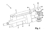
- a linear cylinder unit 1 comprising a pressure cylinder 2 with a cylinder tube 3.
- the end section of the pressure cylinder 2 is sealed up with an end cover member 4.
- a piston 5 is axial displaceable fitted in the cylinder tube 3, whereas a piston rod 6 is connected to the piston 5.
- the piston rod 6 consists of a first part, which is guided through the end cover member 4 to be connected at a peripheral mechanical part and a second part, which extents to the other side of the piston 5 to protrude into the piston locking unit 7.
- the end of the second part of the piston rod features a taper leading shape 9, in order to snap into a bore 10, arranged in a locking element 8, when the piston 5 moves in the direction to the piston locking unit 7.
- the piston locking unit 7 is removable mounted to the rear end of the pressure cylinder 2, and comprises a locking element 8, which is linear movable in a perpendicularly direction to the piston rod 6.
- the locking element 8 comprises a bore 10, whereby the end of the piston rod 6 protrudes through the bore 10 in the shown end position of the piston 5.
- the upper end section of the locking element 8 features a piston 11, which is axially displaceable in a pressure chamber 12 in the housing 13 of the piston locking unit 7.
- the pressure chamber 12 can be pressurised by a pressure medium, in order to cause an axial movement of the locking element 8, whereby in the pressurised condition of the piston 11 the position of the locking element 8, and the bore 10, respectively, releases the piston rod 6.
- a spring element 14 placed in an opposite direction, resets the locking element 8 into a locking position, whereby the spring element 14 is designed as a compression spring.
- the pressure medium is supplied by an external pressure medium, whereby the feed line is not shown in the drawing in fig. 1.
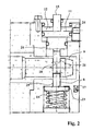
- fig. 2 is shown a detailed view of the piston locking unit 8 with an engaged locking element in the recess of the piston rod.
- the force transmission happens through the shoulder 21 of the recess 18, whereby the shown position of the locking element 8 is the locking position.
- the detecting device 17 is carried out as an electromagnetic sensor, which detects a magnet washer 23, arranged on the locking unit 8 next to the spring 14.
- the pressure port 24 is performed as the pressure connection to the pressure chamber 12.
- a manual override 15 is performed on the side of the piston 11 of the locking unit 8, which provides a mechanical coupling of the locking unit 8 with an external mechanical device. By this coupling the locking unit 8 can be moved in its linear direction by a thrust into the manual override 15, in particular for a manual releasing of the piston rod 6.
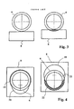
- the contact area is small, because the shape of the locking element 8 is not adapted to the contact area of the shoulder of the recess 18. Therefore the contact area is limited by the diameter of the piston rod and the depth of the recess, and is formed like a section of a circle.
- the contact area related to the invention is shown in fig. 4.
- the bore 10 consists of a releasing section 19 and a locking section 20.
- the left part of fig. 4 shows the piston locking unit 7 in a non locking condition, because the releasing section 19 of the bore 10 features a larger diameter as than the piston rod 6, whereby the piston rod 6 runs through the locking element 8 unaffected.
- the right part of fig. 4 shows the piston locking unit 7 in a locking condition, because the locking section 20 of the bore 10 features a smaller diameter as than the piston rod 6.
- the diameter of the locking section 20 agrees with the inner diameter of the recess 18.
- the contact area 22 is crescent - shaped, by what the contact area in between the shoulder 21 of the recess 18 in the piston rod 6 and the edge of the locking element 8 is as large as possible.
Landscapes
- Engineering & Computer Science (AREA)
- Physics & Mathematics (AREA)
- Fluid Mechanics (AREA)
- Mechanical Engineering (AREA)
- General Engineering & Computer Science (AREA)
- Actuator (AREA)
Applications Claiming Priority (1)
| Application Number | Priority Date | Filing Date | Title |
|---|---|---|---|
| DE102004059201A DE102004059201A1 (de) | 2004-12-09 | 2004-12-09 | Linearzylindereinheit |
Publications (2)
| Publication Number | Publication Date |
|---|---|
| EP1669612A2 true EP1669612A2 (de) | 2006-06-14 |
| EP1669612A3 EP1669612A3 (de) | 2008-01-23 |
Family
ID=35849557
Family Applications (1)
| Application Number | Title | Priority Date | Filing Date |
|---|---|---|---|
| EP05111866A Withdrawn EP1669612A3 (de) | 2004-12-09 | 2005-12-08 | Linearzylindereinheit mit Verriegelung |
Country Status (2)
| Country | Link |
|---|---|
| EP (1) | EP1669612A3 (de) |
| DE (1) | DE102004059201A1 (de) |
Cited By (12)
| Publication number | Priority date | Publication date | Assignee | Title |
|---|---|---|---|---|
| WO2009005361A1 (en) * | 2007-07-03 | 2009-01-08 | National Oilwell Norway As | Lock for axial locking of a piston rod coupling of a hydraulic ram to the body of the hydraulic ram |
| CN102011764A (zh) * | 2010-06-05 | 2011-04-13 | 常州液压成套设备厂有限公司 | 液压油缸锁定装置 |
| CN101725590B (zh) * | 2009-11-30 | 2011-11-16 | 南京康尼机电股份有限公司 | 一种带锁闭单元的气驱动装置 |
| CN103148050A (zh) * | 2011-12-06 | 2013-06-12 | 北京市三一重机有限公司 | 一种液压油缸及液压系统 |
| CN104006022A (zh) * | 2014-05-29 | 2014-08-27 | 芜湖市银鸿液压件有限公司 | 自动往复机械定位升降坝液压缸 |
| CN105114396A (zh) * | 2015-09-18 | 2015-12-02 | 常州液压成套设备厂有限公司 | 液压启闭机液压油缸的锁定装置 |
| CN105422548A (zh) * | 2015-12-29 | 2016-03-23 | 常州液压成套设备厂有限公司 | 液压启闭机油缸旋转式锁定装置 |
| CN109798280A (zh) * | 2019-01-25 | 2019-05-24 | 新昌县三特自动化科技有限公司 | 伺服油缸的自动锁紧机构 |
| IT201900006566A1 (it) * | 2019-05-06 | 2020-11-06 | Camozzi Automation S P A | Cilindro con dispositivo bloccastelo |
| CN113294402A (zh) * | 2021-06-23 | 2021-08-24 | 乐清市恒一气动有限公司 | 一种自锁气缸 |
| IT202100004592A1 (it) * | 2021-02-26 | 2022-08-26 | Camozzi Automation S P A | Cilindro con dispositivo bloccastelo |
| IT202100007511A1 (it) * | 2021-03-26 | 2022-09-26 | Pneumax S P A | Unita’ di attuazione del tipo a leva articolata o a camma con gruppo di auto-ritenuta integrato |
Citations (2)
| Publication number | Priority date | Publication date | Assignee | Title |
|---|---|---|---|---|
| WO2001092732A1 (en) | 2000-05-31 | 2001-12-06 | Razorback Vehicles Corporation Limited | A hydraulic or pneumatic cylinder |
| US6598513B2 (en) | 2000-12-11 | 2003-07-29 | Smc Kabushiki Kaisha | Cylinder apparatus |
Family Cites Families (5)
| Publication number | Priority date | Publication date | Assignee | Title |
|---|---|---|---|---|
| US3453937A (en) * | 1967-09-14 | 1969-07-08 | Lionel Pacific Inc | Hydraulic actuator with proximity sensor of locked condition |
| JPS52154976A (en) * | 1976-06-18 | 1977-12-23 | Teijin Seiki Co Ltd | Actuator |
| DE4016632A1 (de) * | 1990-05-23 | 1991-11-28 | Knorr Bremse Ag | Betaetigungszylinder, insbesondere doppelt wirkender tuerschliesszylinder fuer schienenfahrzeuge |
| DE19521783B4 (de) * | 1994-07-13 | 2004-07-29 | Hoerbiger Hydraulik Gmbh | Druckmittelbetätigbarer Arbeitszylinder |
| DE4427734C2 (de) * | 1994-08-05 | 1996-11-07 | Wolfgang Dipl Ing Niemann | Antriebszylinder für Pressen, Stanzen, Prägemaschinen oder dergleichen |
-
2004
- 2004-12-09 DE DE102004059201A patent/DE102004059201A1/de not_active Ceased
-
2005
- 2005-12-08 EP EP05111866A patent/EP1669612A3/de not_active Withdrawn
Patent Citations (2)
| Publication number | Priority date | Publication date | Assignee | Title |
|---|---|---|---|---|
| WO2001092732A1 (en) | 2000-05-31 | 2001-12-06 | Razorback Vehicles Corporation Limited | A hydraulic or pneumatic cylinder |
| US6598513B2 (en) | 2000-12-11 | 2003-07-29 | Smc Kabushiki Kaisha | Cylinder apparatus |
Cited By (14)
| Publication number | Priority date | Publication date | Assignee | Title |
|---|---|---|---|---|
| WO2009005361A1 (en) * | 2007-07-03 | 2009-01-08 | National Oilwell Norway As | Lock for axial locking of a piston rod coupling of a hydraulic ram to the body of the hydraulic ram |
| CN101725590B (zh) * | 2009-11-30 | 2011-11-16 | 南京康尼机电股份有限公司 | 一种带锁闭单元的气驱动装置 |
| CN102011764A (zh) * | 2010-06-05 | 2011-04-13 | 常州液压成套设备厂有限公司 | 液压油缸锁定装置 |
| CN103148050A (zh) * | 2011-12-06 | 2013-06-12 | 北京市三一重机有限公司 | 一种液压油缸及液压系统 |
| CN104006022A (zh) * | 2014-05-29 | 2014-08-27 | 芜湖市银鸿液压件有限公司 | 自动往复机械定位升降坝液压缸 |
| CN105114396A (zh) * | 2015-09-18 | 2015-12-02 | 常州液压成套设备厂有限公司 | 液压启闭机液压油缸的锁定装置 |
| CN105422548A (zh) * | 2015-12-29 | 2016-03-23 | 常州液压成套设备厂有限公司 | 液压启闭机油缸旋转式锁定装置 |
| CN109798280A (zh) * | 2019-01-25 | 2019-05-24 | 新昌县三特自动化科技有限公司 | 伺服油缸的自动锁紧机构 |
| IT201900006566A1 (it) * | 2019-05-06 | 2020-11-06 | Camozzi Automation S P A | Cilindro con dispositivo bloccastelo |
| EP3736453A1 (de) * | 2019-05-06 | 2020-11-11 | Camozzi Automation S.p.A. | Zylinder mit stangenverrieglungsvorrichtung |
| IT202100004592A1 (it) * | 2021-02-26 | 2022-08-26 | Camozzi Automation S P A | Cilindro con dispositivo bloccastelo |
| IT202100007511A1 (it) * | 2021-03-26 | 2022-09-26 | Pneumax S P A | Unita’ di attuazione del tipo a leva articolata o a camma con gruppo di auto-ritenuta integrato |
| EP4063071A1 (de) * | 2021-03-26 | 2022-09-28 | Pneumax S.p.A. | Betätigungseinheit |
| CN113294402A (zh) * | 2021-06-23 | 2021-08-24 | 乐清市恒一气动有限公司 | 一种自锁气缸 |
Also Published As
| Publication number | Publication date |
|---|---|
| DE102004059201A1 (de) | 2006-06-22 |
| EP1669612A3 (de) | 2008-01-23 |
Similar Documents
| Publication | Publication Date | Title |
|---|---|---|
| EP1669612A2 (de) | Linearzylindereinheit mit Verriegelung | |
| JP5337045B2 (ja) | ピンチ弁 | |
| CN100402229C (zh) | 转动夹具 | |
| TWI533967B (zh) | Clamping device | |
| KR102029325B1 (ko) | 유체압 실린더 | |
| JP4989525B2 (ja) | ロボットハンド | |
| EP2303505B1 (de) | Abstreifstiftklemme | |
| EP3791096B1 (de) | Durchflussregelventilanordnung und zugehöriges einstellwerkzeugset | |
| KR20180097650A (ko) | 밸브, 특히 4/2 방향 슬라이드 밸브 | |
| US10400921B2 (en) | Axial swage tool | |
| US8033025B2 (en) | Shearing tool with device for detecting conclusion of action | |
| EP3603905A1 (de) | Greifvorrichtung | |
| US6308613B1 (en) | Fluid pressure cylinder having lock mechanism | |
| EP4050224B1 (de) | Kopplungsvorrichtung | |
| CN112703323A (zh) | 流体压力缸 | |
| CA2409557A1 (en) | Spring brake cylinder with an emergency release device | |
| ES2527247T3 (es) | Sistema de sujeción universal para sujetar una pieza de trabajo | |
| JP4174670B2 (ja) | パイロット式電磁弁 | |
| EP1165967B1 (de) | Kolben- zylinder- vorrichtung mit mittel zur verriegelung der kolbenstange | |
| EP4063071B1 (de) | Betätigungseinheit | |
| EP0648942B1 (de) | Lineares pneumatisches Stellorgan mit einer umorientierbaren Verriegelungseinrichtung | |
| CZ2000638A3 (cs) | Uvolňovací jednotka zařízení pro ovládání upínací hlavy | |
| JP2009196080A (ja) | ワン・フィンガー・グリッパー装置 | |
| JP7300342B2 (ja) | ケーブルチェンのガイド機構 | |
| US6595104B2 (en) | Pilot control for a hoist and balancing apparatus |
Legal Events
| Date | Code | Title | Description |
|---|---|---|---|
| PUAI | Public reference made under article 153(3) epc to a published international application that has entered the european phase |
Free format text: ORIGINAL CODE: 0009012 |
|
| AK | Designated contracting states |
Kind code of ref document: A2 Designated state(s): AT BE BG CH CY CZ DE DK EE ES FI FR GB GR HU IE IS IT LI LT LU LV MC NL PL PT RO SE SI SK TR |
|
| AX | Request for extension of the european patent |
Extension state: AL BA HR MK YU |
|
| PUAL | Search report despatched |
Free format text: ORIGINAL CODE: 0009013 |
|
| AK | Designated contracting states |
Kind code of ref document: A3 Designated state(s): AT BE BG CH CY CZ DE DK EE ES FI FR GB GR HU IE IS IT LI LT LU LV MC NL PL PT RO SE SI SK TR |
|
| AX | Request for extension of the european patent |
Extension state: AL BA HR MK YU |
|
| AKX | Designation fees paid | ||
| STAA | Information on the status of an ep patent application or granted ep patent |
Free format text: STATUS: THE APPLICATION IS DEEMED TO BE WITHDRAWN |
|
| 18D | Application deemed to be withdrawn |
Effective date: 20080724 |
|
| REG | Reference to a national code |
Ref country code: DE Ref legal event code: 8566 |