EP1669655A1 - Raccord fluide avec bague de retenue à double fonction - Google Patents
Raccord fluide avec bague de retenue à double fonction Download PDFInfo
- Publication number
- EP1669655A1 EP1669655A1 EP05026468A EP05026468A EP1669655A1 EP 1669655 A1 EP1669655 A1 EP 1669655A1 EP 05026468 A EP05026468 A EP 05026468A EP 05026468 A EP05026468 A EP 05026468A EP 1669655 A1 EP1669655 A1 EP 1669655A1
- Authority
- EP
- European Patent Office
- Prior art keywords
- carrier
- fluid coupling
- bore
- extending
- retention ring
- Prior art date
- Legal status (The legal status is an assumption and is not a legal conclusion. Google has not performed a legal analysis and makes no representation as to the accuracy of the status listed.)
- Withdrawn
Links
- 239000012530 fluid Substances 0.000 title claims abstract description 90
- 230000008878 coupling Effects 0.000 title claims abstract description 61
- 238000010168 coupling process Methods 0.000 title claims abstract description 61
- 238000005859 coupling reaction Methods 0.000 title claims abstract description 61
- 230000014759 maintenance of location Effects 0.000 title claims abstract description 51
- 230000009977 dual effect Effects 0.000 title description 3
- 238000000465 moulding Methods 0.000 claims description 4
- 239000007787 solid Substances 0.000 claims description 4
- 238000007789 sealing Methods 0.000 claims 3
- 230000007704 transition Effects 0.000 description 16
- 238000003780 insertion Methods 0.000 description 15
- 230000037431 insertion Effects 0.000 description 15
- 239000000463 material Substances 0.000 description 9
- 229920003023 plastic Polymers 0.000 description 7
- 239000004033 plastic Substances 0.000 description 7
- 238000000034 method Methods 0.000 description 6
- 239000002184 metal Substances 0.000 description 4
- 229920003020 cross-linked polyethylene Polymers 0.000 description 2
- 239000004703 cross-linked polyethylene Substances 0.000 description 2
- 230000008569 process Effects 0.000 description 2
- 238000013459 approach Methods 0.000 description 1
- 238000005452 bending Methods 0.000 description 1
- 230000002950 deficient Effects 0.000 description 1
- 230000001788 irregular Effects 0.000 description 1
- 230000013011 mating Effects 0.000 description 1
- 238000002844 melting Methods 0.000 description 1
- 230000008018 melting Effects 0.000 description 1
- 230000002093 peripheral effect Effects 0.000 description 1
- 238000000926 separation method Methods 0.000 description 1
- 238000003466 welding Methods 0.000 description 1
Images




Classifications
-
- F—MECHANICAL ENGINEERING; LIGHTING; HEATING; WEAPONS; BLASTING
- F16—ENGINEERING ELEMENTS AND UNITS; GENERAL MEASURES FOR PRODUCING AND MAINTAINING EFFECTIVE FUNCTIONING OF MACHINES OR INSTALLATIONS; THERMAL INSULATION IN GENERAL
- F16L—PIPES; JOINTS OR FITTINGS FOR PIPES; SUPPORTS FOR PIPES, CABLES OR PROTECTIVE TUBING; MEANS FOR THERMAL INSULATION IN GENERAL
- F16L37/00—Couplings of the quick-acting type
- F16L37/08—Couplings of the quick-acting type in which the connection between abutting or axially overlapping ends is maintained by locking members
- F16L37/084—Couplings of the quick-acting type in which the connection between abutting or axially overlapping ends is maintained by locking members combined with automatic locking
- F16L37/091—Couplings of the quick-acting type in which the connection between abutting or axially overlapping ends is maintained by locking members combined with automatic locking by means of a ring provided with teeth or fingers
Definitions
- the present invention relates, in general, to fluid couplings for joining fluid carrying components.
- Fluid connections or couplings are known for interconnecting metal or plastic tubes to each other.
- One of the tubes can also be a fluid operative component, such as a valve, manifold, pump, etc.
- Such fluid connectors typically employ a retainer in the form of a ring with radially inward extending, flexible, spring-like fingers which bite into the smooth, constant diameter, tip end of the tube.
- the fingers allow removal of the tube by means of a release tool which is inserted into engagement with the inner surface of the fingers to deflect the fingers away from the tube.
- the retainer fingers can scratch the surface of the tube during insertion of the tube into the housing carrying the retainer or upon removal of the tube from the housing. These scratches can form leak paths through the seal elements or O-rings mounted on the tube or can damage the seal elements, again leading to fluid leak paths and a defective fluid coupling.
- an end flange on the coupling is non-removably joined to the fluid use component or housing by sonic or heat welding which forces the use of like materials with like melt temperatures, i.e., plastics, that would bond together.
- the present invention is a fluid coupling for joining two fluid use or fluid operative elements, such as conduits, valves, pumps, etc.
- the fluid coupling includes a fluid use element having a bore extending from an open end.
- the bore has an inner surface.
- a carrier has a bore extending between first and second ends, with at least one aperture formed in the carrier intersecting the bore.
- a retention ring is mounted on the carrier and has at least one inward extending finger with the tip end extending through the aperture into the bore in the carrier, and at least one outward extending finger having a tip end extending outward from the carrier.
- the tip end of the outward extending finger engages the inner surface of the bore in the fluid use element to fix the carrier to the fluid use element.
- the tip end of the inward extending finger on the retention ring engages the endform to fix the endform to the carrier.
- Inner and outer seals are disposed on the carrier.
- the seals can be separate O-rings or integrally carried on the carrier through a double shot molding process with the carrier.
- the inner seal which seals an endform to a fluid use element to an endform inserted into the bore in the carrier with the carrier is disposed axially from the tip end of the inward extending fingers on the retention ring such that any portion of the service of the endform which is contacted by the inward extending fingers does not contact the seal element.
- a plurality of inward extending fingers or a plurality of outwardly extending fingers are provided with a helical pitch by helically varying the length of the fingers about the circumference of the retention ring. This enables, in the case of a helical pitch formed on the inward extending fingers, for the endform to be unthreaded from the joined carrier and housing. In the case of a helical pitch on the outward extending fingers, the entire carrier and endform can be unthreaded from the housing.
- the present fluid coupling provides improvements over existing fluid couplings by utilizing the same retainer to removably join the connector components to the fluid use element or outer housing as well as to join the endform or tube to the connector.
- the connector components of the present fluid coupling may also be assembled in two different ways, including fixed insertion in the fluid use element or housing prior to insertion of the endform into the housing or on the endform prior to joined insertion into the housing.
- the present fluid coupling also spaces the seal elements axially from the retainer so as so prevent any scratches which may be formed in the surface of the endform by the retainer during endform insertion or removal from contacting the seal elements and damaging the seal elements or otherwise forming leak paths through the seal elements.
- the present fluid coupling also has a configuration which enable easy removal of the entire connector components from the fluid use element or housing.
- Fig. 1 is an exploded, perspective view of one aspect of a fluid coupling
- Fig. 2 is a perspective view of the fluid coupling shown in Fig. 1;
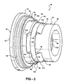
- Fig. 3 is a perspective view of the carrier and the retention ring shown in Figs. 1 and 2;
- Fig. 4 is a longitudinal, cross sectional view of the carrier and retention ring shown in Fig. 3;
- Fig. 5 is a perspective view of the retention ring shown in Figs. 1-4;
- Fig. 6 is a perspective view of another aspect of a fluid coupling
- Fig. 7 is an exploded, perspective view of the fluid coupling shown in Fig. 6;
- Fig. 8 is a perspective view of the carrier, the retention ring and the seal element of the fluid coupling shown in Figs. 6 and 7;
- Fig. 9 is a side elevational view of the carrier, the retention ring and the seal elements shown in Fig. 8;
- Fig. 10 is a left end view of the carrier, the retention ring and the seal element shown in Fig. 9;
- Fig. 11 is a longitudinal cross sectional view of the fluid coupling shown in Fig. 6.
- a fluid coupling is formed between two components, such as an endform and a fluid use element.
- the fluid use element can be any fluid carrying or fluid operative element, including a tube or conduit, a housing having a through bore, an endform, a valve, pump, or manifold, etc.
- An endform is defined as the geometry or shape on the end of a tubular member or fluid use element, typically having a through bore extending from an open end.
- the geometry or shape on the end of a tubular member which is defined by the term "endform” is meant to include any geometry or shape, including a smooth, constant diameter end, such as a straight, round tube end, as well as a tube end which has an irregular shape or profile other than a constant, smooth diameter.
- a fluid coupling 20 fluidically and sealingly couples an endform 22 to a fluid use element, hereafter defined as a housing 24.
- the endform 22 has a tubular, cylindrical shape with a bore 26 extending from an open first end 28.
- the endform 22 may be formed of any suitable material, such as metal, plastic, etc.
- the housing 24 also has an open first end 30.
- a bore 32 extends through the housing 24 from the first end 30.
- the bore 32 is a stepped bore formed of a first large diameter bore 34 extending from the first end 30, a second smaller diameter bore 36 extending axially from the first bore 34, a third bore 38 extending axially from the second bore 36, and a fourth bore 40 extending axially from the third bore 38.
- a fifth bore 42 is shown in Fig. 1 by way of example only extending from the fourth bore 40.
- the first and second bores 34 and 36 are separated by a surface 44 generally in the form of a shoulder extending perpendicularly from an outer surface 46 of the housing 24.
- the second and third bores 36 and 38, respectively, are separated by a surface 48.
- the surface 48 defines a ramp or angled surface with respect to the outer surface 46 or a longitudinal axis of the housing 24.
- the third and forth bores 38 and 40, respectively, are likewise separated by a surface 50 which is also angled or ramped with respect to the outer surface 46 ro longitudinal axis of the housing 24.
- the angled or ramped surfaces 48 and 50 define support surfaces for finger portions of the retention ring or retainer as described hereafter.
- the fluid coupling 20 also includes a carrier 60 which may be in the form of a one-piece molded or machined body 62.
- the body 62 may be formed of a suitable material, such as metal, plastic, etc.
- the body 62 has a first end 64 and an opposed second end 66.
- a bore 68 extends between the first and second ends 64 and 66.
- the outer surface of the body 62 has a stepped configuration formed of an end flange 70 adjacent the first end 64.
- a shoulder 72 defines an angled or generally perpendicular transition from the flange 70 to a reduced diameter ring 74.
- the ring 74 forms a seat for an outer seal element 76.
- a shoulder 78 extending by way of example only, perpendicularly to the major surface of the ring 74, forms a transition between the ring 74 and a second ring 80.
- a generally cylindrical, constant diameter sleeve 82 is connected to the second ring 80 by a transition surface 84.
- the sleeve 82 extends from the transition surface 84 to the second end 66 of the body 62.
- the transition surface 84 includes a generally perpendicular wall 86 extending from one end of the sleeve 82. The radially outer end of the wall 86 transitions into an angled or ramped surface 88 extending to one end of the second ring 80.
- a plurality of notches 90 are formed in the transition surface 84 and extend between the sleeve 82 and the second ring 80. The notches 90 are equidistantly spaced and provided at the same spacing and in the same number as the number of outer fingers on the retention ring as described hereafter. The notches 90 form a seat or bearing surface for the outer fingers on the retention ring.
- a plurality of apertures such as three, by way of example only, for a retention ring having three radially inward extending fingers are formed in the sleeve 82 intermediate the second end 66 and the transition surface 84.
- the apertures or windows 92 open to the bore 68 in the body 62 as shown in Figs. 2 and 3.
- An angled surface 94 is formed through the sleeve 82 and forms one portion of each aperture 92.
- the surface 94 forms a support or bearing surface for the radially inward extending fingers, as described hereafter.
- the bore 68 has, by way of example only, a stepped configuration formed of a first diameter bore 96 extending from the first end 64 of the body 62, a second bore 98 extending axially from a shoulder 100 extending perpendicular from one end of the first bore 96, and a third bore 102 extending from a generally perpendicular shoulder 104 projecting from one end of the bore 98.
- a retainer or retention ring 110 is mounted on the carrier body 62 and serves the dual function of fixing the endform 22 to the carrier 60 as well as fixing the carrier 60 in the housing 24.
- the retention ring 110 which may be formed of a suitable material, typically metal or high strength plastic having resilient and spring characteristics, has an annular band or ring 112 with a diameter to seat on the sleeve 82 of the carrier body 62 as shown in Figs. 2-4.
- At least one or a plurality of radially inward and angularly extending latch members or fingers extend from the band 112.
- three latch fingers 114, 116 and 118 extend from one edge of the band 112.
- the fingers 114, 116 and 118 are supported by the surface 94 in each aperture 92.
- each latch finger 114, 116 118 has an inner tip end, all denoted generally by reference number 120, which extends through each aperture 92 and into the bore 98. This positions the tip ends 120 for fixed engagement with the first endform 22 as shown in Fig. 1.
- the inward extending latch fingers 114, 116 and 118 bend outwards along the surface of the sleeve 82 until the retention ring 110 seats against the surface 86 as shown in Figs. 1 and 3.
- the tip ends 120 of the inner latch fingers 114, 116 and 118 are aligned with the apertures 92 and snap back to their normal, radially inward, angled position shown in Figs. 2-6. This places the tip ends 120 of the each the latch fingers 114, 116 and 118 in an interference position with respect to the outer surface of the endform 22.
- the tip ends 120 of the latch fingers 114, 116 and 118 will engage and dig into the outer surface of the endform 22. Due to the radially inward extending, angular position of each latch finger 114, 116 and 118, reverse movement in a direction to separate the endform 22 from the carrier body 62 is resisted by the inner latch fingers 114, 116 and 118.
- the retention ring 110 includes a plurality of radially outward, angled latch fingers, with three outer latch fingers 122, 124 and 126 being shown by way of example.
- the outer latch fingers 112, 124 and 126 extend from the opposite side edge of the band 112 in a radially outward, angled direction opposite from the radially inward, angled direction of extent of the inner latch fingers 114, 116 and 118.
- Each outer latch finger 122, 124 and 126 is supported on the surface 90 on the carrier body 62 and is disposed within one of the notches 90. This maintains the retention ring 110 in position on the carrier body 62 and, in conjunction with the disposition of the inner fingers 114, 116 and 118 in the apertures 92 in the carrier body 62, resists rotation and separation of the retention ring 110 from the carrier body 62.
- each outer latch finger 122, 124 and 126 has an outer tip end 128 which is disposed in an interference position with the inner surface of the bore 36 in the housing 24.
- the tip ends 128 of each of the outer latch fingers 122, 124 and 126 will engage and dig into the inner surface of the bore 36.
- the angular position of each of the outer latch fingers 122, 124 and 126 resists movement of the carrier 62 in an opposite direction from the insertion direction so as to fixedly hold the carrier 60 in the housing 24.
- Each of the inner latch fingers 114, 116 and 118 is formed of a generally planar, solid member. It will be understood that each of the inner latch fingers 114, 116 and 118 can be formed of a plurality of separately movable, cantilevered fingers.
- Each of the outer latch fingers 122, 124 and 126 is formed, by example only, of a planar, solid member. It will be understood that each of the outer latch fingers 122, 124 and 126 can be formed of a plurality of separately movable, cantilevered fingers.
- the angled or ramped surface 50 in the housing 24 opposes and is generally parallel to the angled surface 94 in the carrier body 62. This provides an opening for one of the inner latch fingers 114, 116 or 118.
- the angled surface 48 in the housing 24 opposes and is generally parallel to the angled or ramped surface 90 on the carrier body 60 to form a slot for receiving one of the outer latch fingers 122, 124 and 126
- a plurality of seal elements are formed or disposed on the carrier 60 to seal the carrier to the housing 24 and to the endform 22.
- the seal elements include an outer seal element 72 and the inner seal element 106.
- the outer and inner seal elements 72 and 106 may be formed as separate members from the carrier 60, in one aspect, the inner and outer seal elements 72 and 74 are integrally and fixedly joined to the carrier body 62 by a double shot molding process. This requires that the seal elements 72 and 106 be formed of a material compatible with the molding temperature of the material forming the carrier body 62.
- each inner and outer seal element 72 and 106 is formed with one or more lobes, such as lobes 130 and 132 for the outer seal elements 72 and lobes 134 and 136 for the inner seal element 106.
- the outer seal element 72 seats on the first ring surface 74 on the carrier body 62.
- the inner seal element 106 seats on the inner surface of the bore 96 and substantially abuts the shoulder 100 in the carrier body 62.
- the fluid coupling 20 can be assembled in two different methods. Both methods start with the seal elements 72 and 106 formed on or otherwise disposed on the carrier body 62.
- the retention ring 110 is also mounted on the carrier body 62 as described above.
- the carrier body 62 is inserted through the open first end 30 of the housing 24 as shown in Fig. 2 until the shoulder 78 on the carrier body 62 abuts the shoulder 44 in the housing 24. At this time, the tip ends 128 of the outer latch fingers 122, 124 and 126 engage and dig into the inner surface of the bore 36 in the housing 24 to fixedly latch the carrier 60 to the housing 24.
- the lobes 130 and 32 of the outer seal element 72 are compressed to fluidically seal the carrier body 62 to the housing 24.
- the tip end of the endform 22 is inserted through the open end 64 of the carrier 60 as shown in Fig. 1. During this insertion, the outer surface of the tip end 22 first sealingly engages the with lobes 134 and 136 of the inner seal element 106. Insertion of the endform 22 continues until the first end 28 abuts the shoulder 104 at the end of the inner bore 98 and the beginning of the bore 102. As the first end 28 of the endform 22 approaches the shoulder 104, the tip ends 120 of the inner latch fingers 114, 116 and 118 engage and dig into the outer surface of the endform 22.
- the carrier 60, retention ring 110, and inner and outer seals 72 and 106 are assembled as described above.
- the first end 28 of the endform 22 is then inserted into the bore 68 of the carrier 60 through the open first end 64 as described above.
- the inner latch fingers 114, 116 and 118 retain the carrier 60 on the end of the endform 22.
- the assembled endform 22 and carrier 60 are then inserted as a unit through the open first end 30 of the housing 20. Due to the different diameter and tapered surface of the bores 36, 38 and 46, respectively, the tip ends 128 of the outer latch fingers 122, 124 and 126 do not engage the inner surface of the bore 36 until the carrier 60 is substantially fully inserted into the bore 32 in the housing 24. At this time, the tip ends 128 of the outer latch fingers 122, 124 and 126 engage the inner surface of the bore 36 in the housing 24 to fix the carrier 60 and the attached endform 22 in the housing 24.
- outer seal element 72 is axially spaced on the carrier body 62 from the tip ends 28 of the outer latch fingers 122, 124 and 126 and is disposed within a different bore 34 than the bore 36 engaged by the outer latch fingers 122, 124 and 126 so as to prevent any scrapping or surface disruptions of the bore 34 which will be engaged by the outer seal element 72.
- FIG. 6-11 there is depicted another aspect of a fluid coupling 150 which is used to fluidically couple an endform, such as the endform 22 described above and shown in Figs. 1-3 to a fluid use element 152 depicted in Fig. 11 as being in the form of a housing.
- the fluid coupling 150 includes a carrier 160 formed of a carrier body 162, an outer seal element, such as an O-ring 164, an inner seal element or O-ring 166, a retainer or retention ring 168, and a top hat 170.
- an outer seal element such as an O-ring 164, an inner seal element or O-ring 166, a retainer or retention ring 168, and a top hat 170.
- the carrier body 162 may be a one-piece body formed of a molded or machined plastic.
- the carrier body 162 includes an end flange 172 which extends from a first end 174 of the carrier body 162.
- the peripheral surface of the end flange 172 may be formed with a plurality of flats 176, such as hex flats, which provide a tool engagement surface for receiving a wrench or socket to facilitate removal of the carrier 162 from the housing 152, as described hereafter.
- a first annular ring 178 projects at a smaller diameter from one end of the end flange 172.
- the first ring 178 forms a support surface or seat for the first outer seal element or O-ring 164.
- a shoulder 180 forms a transition between the first ring 178 and a second ring 182 which has a smaller diameter than the first ring 178.
- a transition surface 184 which is disposed at a non-perpendicular angle from the second ring 182, extends from one end of the second ring 182 and transitions into a generally perpendicularly extending flat 186.
- a generally cylindrical sleeve 188 extends axially from the flat 186.
- a plurality of apertures or windows are formed in and through the sleeve 188 generally adjacent to the flat 186.
- Each of the apertures or windows 190, 192 and 194 opens to the interior bore extending through the carrier body 162.
- a plurality of notches such as three notches 196, 198 and 200, for example only, are formed in the sleeve 188 and extend from a second end 202 of the carrier body 162 to each of the apertures 190, 192 and 194, respectively.
- Each of the notches 196, 198 and 200 forms a reduced diameter portion, aligned with one of the windows 190, 192 and 194 ,to orient the inner latch fingers of the retention ring 168 and to prevent over bending of the inner latch fingers beyond their normal capacity to resiliently return to a nominal position during insertion of the retention ring 168 on the sleeve 188.
- each notch 196, 198 and 200 is angled from the second end 202 of the carrier body 162 to form a ramp surface for the inner latch fingers of the retainer 168 during mounting of the retainer 168 on the sleeve 188 of the carrier body 162, as described hereafter.
- the carrier body 162 has a first bore 210 extending from the first end 174.
- the first bore 128 ends at a shoulder 212 which extends generally perpendicular from the bore 210 to a second smaller diameter bore 214.
- the second bore 214 extends co-axially from the first bore 210 and terminates in an angular shoulder 216 which is generally perpendicular to a longitudinal axis through the carrier body 162.
- the shoulder 216 transitions to a third bore 218 which extends to an end shoulder 220.
- the end shoulder 220 also disposed generally perpendicular to a longitudinal axis through the carrier body 162, transitions into a fourth bore 222 at the second end 202 of the carrier body 160.
- the shoulder 220 forms an insertion limit or stop for receiving the first inserted end of an endform 230, shown in phantom in Fig. 10.
- the shoulder 216 forms a seat for the inner seal element or O-ring 166.
- the second bore 214 is sized to slidably receive a sleeve 232 of the top hat 170.
- a flange 234 at one end of the sleeve 232 of the top hat 170 seats within the first bore 210 against the shoulder 212.
- the top hat 170 functions to hold the second seal element 166 in the carrier body 160.
- the retainer 168 includes a central ring 240.
- the retainer 168 When the retainer 168 is mounted on the sleeve 188 of the carrier body 162, the generally flat ring 240 seats against the flat 188 on the carrier body 162. This places the major surfaces of the ring or band 240 at an angle, typically perpendicular, to the longitudinal axis of the carrier body 162 thereby increasing the pullout resistance provided by the retention ring between the carrier body 162, the endform 23 0 and the housing 152.
- the retention ring 168 also includes at least one or more inner latch fingers, each denoted by reference number 242.
- the inner latch fingers are arranged in three equi-circumferentially spaced groups of inner latch fingers 244, 246 and 248, each formed of at least one and, typically, more than one latch finger, with three latch fingers 242 forming each of the groups 244, 246 and 248.
- Each of the latch fingers 242 in each group 244, 246 and 248 is also equally spaced from adjacent latch fingers 242 in each group 244, 246 and 248.
- the latch fingers 242 extends through the apertures 190, 192 and 194 in the sleeve 188 of the carrier body 162 and have a tip end 250 which projects radially inward of the inner surface of the bore 218 so as to be disposed in an interference position with the outer surface of the endform 230.
- the latch fingers 242 in each group of latch fingers 244, 246 and 248 slide along the ramp surface on the end of the notches 196, 198 and 200 and bend radially outward until the ring 240 of the retention ring 168 is inserted sufficiently far enough over the sleeve 188 to enable the tips ends 250 of the latch fingers 244 to snap back to their nominal position shown in Fig. 10.
- the retention ring 168 also includes at least one or more outer latch fingers 254.
- the plurality of latch fingers 254 are equi-circumferentially spaced about the entire periphery of the ring 240.
- the outer latch fingers 254 may be provided in more or less numbers than that illustrated in Figs. 6-9 as well as being provided in circumferentially spaced groups skin to the groups 244, 246, 248 of the inner latch fingers 242.
- Each of the outer latch fingers 254 terminates in a radially outer tip 256 which is disposed radially and angularly outward from one edge of the ring 240 of the retention ring 268.
- the tip 256 of each outer latch finger 254 is disposed in an interference position with respect to an inner surface of the housing 152.
- the housing 152 includes a first end 260 and an opposed second end 262.
- a bore means extends between the first and second ends 260 and 262.
- the bore means includes a first bore 264 extending from the first end 260 which terminates in a perpendicularly extending shoulder 266.
- a second bore 268 extends from a radially inner edge of the shoulder 266 to a transition surface which forms a ramp or angled surface 270 with respect to a longitudinal axis extending through the housing 162.
- a third bore 272 extends from the transition surface 270 to an end shoulder 274.
- the end shoulder 274 transitions into a fourth bore 276.
- the carrier body 160 carrying the seals 164 and 166, the retention ring 168 and the top hat 170, after preassembly, may be mounted on the end of the endform 230 prior to insertion of the carrier 160 and endform 230 into the housing 252.
- the carrier 260 may be pre-mounted in the housing 152 and then the endform 230 inserted and latched to the carrier 160.
- the outer or first seal 164 seats between the first ring 178 of the carrier 160 and the spaced inner bore 164 of the housing 152 to seal the carrier 160 to the housing 162.
- the second seal element 166 seats against the shoulder 216 and the carrier 160 and is held in the carrier 160 by the top hat 170.
- the inner or second seal element 166 is axially spaced outward with respect to the insertion direction of the endform 230 into the carrier 160. In this manner, any portion of the outer surface of the endform 230 which is engaged and which may be scratched by the tip ends 250 of the inner latch fingers 242 does not come into contact with the inner surface of the second seal element 166.
- the ring 240 extends generally perpendicularly with respect to the longitudinal axis of the coupling 150. This provides a stronger seat or mount of the retainer 168 between the carrier 160 and the housing 152 than the generally horizontal disposition of the band 112 of the retention ring 110 in the first aspect of the fluid coupling 20.
- the inner latch fingers 242 or the outer latch fingers 254 may be provided with a helical or spiral configuration about the circumference of the retention ring 168. This can be achieved by varying the length of each inner latch finger 244 or each outer latch finger 254 starting with a first shortest length inner latch finger 242 or outer latch finger 254 and gradually increasing the length of each adjacent inner latch finger 242 or outer latch finger 254 going about the circumference of the retainer 168 to a longest length inner latch finger 242 or outer latch finger 244. This creates a helical arrangement of the tip ends 250 of the inner latch fingers 242 or the tip ends 256 of the outer latch fingers 254.
- the endform 230 may be unthreaded by applying a rotative unthreading force to the endform 230 or to the joined carrier 160 and housing 152 to separate the housing 152 and carrier 160 from the endform 230.
- the joined endform 230 and carrier 160 may be unthreaded relative to the housing 152 as a complete assembly.
- a single retention ring serves the dual function of latching an endform to a carrier as well as latching the carrier to a mating housing or fluid element.
- the single retention ring enables dissimilar materials with different melt temperatures to be used to construct the quick connect and to join the quick connect to an endform since the endform and the quick connect components are not sonic or heat welded together.
Landscapes
- Engineering & Computer Science (AREA)
- General Engineering & Computer Science (AREA)
- Mechanical Engineering (AREA)
- Quick-Acting Or Multi-Walled Pipe Joints (AREA)
Applications Claiming Priority (1)
| Application Number | Priority Date | Filing Date | Title |
|---|---|---|---|
| US11/008,388 US7341286B2 (en) | 2004-12-09 | 2004-12-09 | Fluid coupling with dual function retention ring |
Publications (1)
| Publication Number | Publication Date |
|---|---|
| EP1669655A1 true EP1669655A1 (fr) | 2006-06-14 |
Family
ID=36024318
Family Applications (1)
| Application Number | Title | Priority Date | Filing Date |
|---|---|---|---|
| EP05026468A Withdrawn EP1669655A1 (fr) | 2004-12-09 | 2005-12-05 | Raccord fluide avec bague de retenue à double fonction |
Country Status (3)
| Country | Link |
|---|---|
| US (1) | US7341286B2 (fr) |
| EP (1) | EP1669655A1 (fr) |
| JP (1) | JP2006242375A (fr) |
Cited By (5)
| Publication number | Priority date | Publication date | Assignee | Title |
|---|---|---|---|---|
| US8342579B2 (en) | 2009-02-03 | 2013-01-01 | Hennemann Thomas L | Push lock pipe connection system |
| US8814219B2 (en) | 2009-02-03 | 2014-08-26 | Bilfinger Water Technologies, Inc. | Push lock pipe connection system and disconnection tool |
| US9810358B2 (en) | 2009-02-03 | 2017-11-07 | Aqseptence Group, Inc. | Male push lock pipe connection system |
| US10221977B2 (en) | 2009-02-03 | 2019-03-05 | Aqseptence Group, Inc. | Pipe coupling |
| US20230265953A1 (en) * | 2020-10-13 | 2023-08-24 | Tyco Fire Products Lp | Push-to-connect fitting systems and methods |
Families Citing this family (34)
| Publication number | Priority date | Publication date | Assignee | Title |
|---|---|---|---|---|
| EP1642058B1 (fr) * | 2003-07-04 | 2007-11-14 | Friatec Aktiengesellschaft | Accouplement enfichable |
| EP1783415B1 (fr) * | 2005-11-04 | 2013-04-17 | Pres-Block S.P.A. | Raccord rapide pour un système de circulation de fluide |
| FR2896572B1 (fr) * | 2006-01-23 | 2009-07-03 | Saint Gobain Pam Sa | Jonction tubulaire |
| PL1962009T3 (pl) * | 2007-02-01 | 2012-05-31 | Conex Uniwersal Ltd | Zespół łącznika rurowego i sposób jego wykonania |
| US7490865B1 (en) * | 2007-07-30 | 2009-02-17 | Tzu Liang Tsai | Quick connector |
| US20090278346A1 (en) * | 2008-05-07 | 2009-11-12 | O'brien Kevin | Connector |
| US8469405B2 (en) * | 2009-10-20 | 2013-06-25 | Dave Wheatley Enterprises, Inc. | Securing mechanism for a coupling device |
| US20110214886A1 (en) * | 2010-03-05 | 2011-09-08 | The Viking Corporation | Push On Threadless Sprinkler And Fitting |
| USD715902S1 (en) | 2012-07-19 | 2014-10-21 | Homewerks Worldwide, LLC | Plumbing fastener |
| USD717408S1 (en) | 2012-07-19 | 2014-11-11 | Homewerks Worldwide, LLC | Plumbing fastener |
| USD702543S1 (en) * | 2012-09-13 | 2014-04-15 | Mueller Industries, Inc. | Swivel nut |
| DE102012108791A1 (de) * | 2012-09-18 | 2014-03-20 | Voss Automotive Gmbh | Bausystem für eine Anschlussvorrichtung für Medienleitungen |
| US8801048B2 (en) | 2012-11-27 | 2014-08-12 | Charlotte Pipe And Foundry Company | Mechanical pipe coupling assembly without adhesive or bonding agent |
| US10006575B2 (en) | 2013-12-11 | 2018-06-26 | Nibco Inc. | Modular push-to-connect assembly |
| US9541228B2 (en) | 2013-12-11 | 2017-01-10 | Nibco Inc. | Push-to-connect fitting |
| US9447906B2 (en) * | 2013-12-11 | 2016-09-20 | Nibco Inc. | Self-locking push-to-connect insert |
| US9777875B2 (en) | 2014-02-26 | 2017-10-03 | Nibco Inc. | Clam shell push-to-connect assembly |
| USD815516S1 (en) * | 2014-09-02 | 2018-04-17 | General Electric Company | Connector joint |
| MX387265B (es) * | 2015-10-16 | 2025-03-18 | Ppc Broadband Inc | Conectores para su uso en la inyección de núcleos de cable coaxial a alta presión e inyección de cables de fibra óptica. |
| ITUA20161872A1 (it) * | 2016-03-21 | 2017-09-21 | Zorsol S R L | Connettore maschio e relativo assieme di connessione perfezionati per il collegamento rimovibile di un gruppo frigorifero ad una piastra di raffreddamento ad uso funerario |
| US10563385B1 (en) * | 2016-05-17 | 2020-02-18 | Wcm Industries, Inc. | Overflow cover interconnection system |
| US10443220B2 (en) | 2016-08-12 | 2019-10-15 | Wcm Industries, Inc. | Device for providing improved drainage |
| US11614191B2 (en) | 2017-09-08 | 2023-03-28 | Tyco Fire Products Lp | Push-to-connect-rotate-to-release sprinkler assembly and fitting with helical gripper ring |
| DE102017123539B3 (de) * | 2017-10-10 | 2019-01-03 | HARTING Electronics GmbH | Leiterkartensteckverbinder mit einem Schirmelement |
| US10962123B2 (en) | 2018-04-23 | 2021-03-30 | Sioux Chief Mfg. Co., Inc. | Push-fit spigot |
| DE102018109998B4 (de) * | 2018-04-25 | 2025-04-17 | Pipe-Aqua-Tec Gmbh & Co.Kg | Rohranschlusssystem |
| US11079055B2 (en) * | 2018-10-30 | 2021-08-03 | Ina Acquisition Corp. | Fitting for connecting a main pipe liner to a branch conduit |
| CA3118286A1 (fr) * | 2018-10-30 | 2020-05-07 | Ina Acquisition Corp. | Raccord pour le raccordement d'un chemisage de tuyau principal a un conduit de derivation |
| EP3951231B1 (fr) * | 2019-03-29 | 2024-01-31 | Proterial, Ltd. | Élément de retenue et raccord de tuyau l'utilisant |
| IT201900005616A1 (it) * | 2019-04-11 | 2020-10-11 | Camozzi Automation S P A | Elemento di raccordo |
| US11149426B2 (en) | 2019-06-12 | 2021-10-19 | Charlotte Pipe And Foundry Company | Toilet assembly having improved closet flange |
| US11814832B2 (en) | 2020-03-13 | 2023-11-14 | Wcm Industries, Inc. | Overflow covers and overflow systems for bathtubs |
| USD1003406S1 (en) | 2020-03-13 | 2023-10-31 | Wcm Industries, Inc. | Cover for a bathtub overflow system |
| KR102833219B1 (ko) * | 2020-05-15 | 2025-07-10 | 현대모비스 주식회사 | 차량의 전장부품으로부터 커넥터 탈거를 방지하기 위한 구조체 |
Citations (4)
| Publication number | Priority date | Publication date | Assignee | Title |
|---|---|---|---|---|
| DE7936914U1 (de) * | 1979-06-06 | 1980-11-06 | Armaturenfabrik Hermann Voss Gmbh + Co, 5272 Wipperfuerth | Verbindungsvorrichtung fuer druckleitungen |
| WO1997003314A1 (fr) * | 1995-07-07 | 1997-01-30 | Marley Tile Ag | Accouplements de tubes par montage a frottement doux |
| DE19800050A1 (de) * | 1997-01-24 | 1998-07-30 | Helmut Feldhoff | Steckvorrichtung für Rohrleitungen |
| EP0972981A2 (fr) * | 1994-09-14 | 2000-01-19 | John Derek Guest | Anneau de retenue |
Family Cites Families (28)
| Publication number | Priority date | Publication date | Assignee | Title |
|---|---|---|---|---|
| US3922011A (en) * | 1973-12-11 | 1975-11-25 | Tom Walters | Hose coupling |
| DD154393A1 (de) | 1980-12-11 | 1982-03-17 | Rudi Schmidt | Steckkupplung fuer gasleitungen |
| US4586734A (en) * | 1982-12-08 | 1986-05-06 | General Industries, Inc. | Pipe joint assembly |
| DE3514018A1 (de) * | 1985-04-18 | 1986-10-23 | Rubber- En Kunststoffabriek Enbi B.V., Nuth | Haltering |
| DE3710852C1 (de) * | 1987-04-01 | 1988-03-10 | Rasmussen Gmbh | Rohrkupplung |
| US4889368A (en) * | 1988-12-12 | 1989-12-26 | Aeroquip Corporation | Combination quick-connect and thread-disconnect tube connector |
| US4911406A (en) * | 1989-01-11 | 1990-03-27 | Accor Technology, Inc. | Fluid conduit coupling apparatus |
| US5022687A (en) * | 1989-09-18 | 1991-06-11 | Yokohama Aeroquip Corporation | Pipe coupling |
| JPH073119Y2 (ja) * | 1989-11-20 | 1995-01-30 | シーケーディ株式会社 | 管継手 |
| JPH0439492A (ja) * | 1990-05-31 | 1992-02-10 | Tokai Rubber Ind Ltd | クイックコネクタ |
| GB9115850D0 (en) * | 1991-07-23 | 1991-09-04 | Univ Manchester | Coupling |
| US5366262A (en) * | 1992-07-23 | 1994-11-22 | Furnas Electric Co. | Quick connect fluid fitting |
| US5443289A (en) * | 1992-11-11 | 1995-08-22 | Guest; John D. | Tube couplings |
| US5573279A (en) * | 1994-01-03 | 1996-11-12 | Form Rite Corporation | Quick connect coupling |
| US5542717A (en) * | 1994-01-03 | 1996-08-06 | Form Rite, Corporation | Quick connect coupling |
| US5662359A (en) * | 1995-08-28 | 1997-09-02 | Form Rite | Quick connect coupling with lock ring and indicator |
| US6347815B1 (en) * | 1995-08-31 | 2002-02-19 | Cooper Technology Services, Llc | Quick connect fluid coupling with components positioned to provide continuous insertion resistance |
| US5730475A (en) * | 1995-10-13 | 1998-03-24 | Form Rite | Quick connect fluid coupling with collet retainer |
| US5887911A (en) * | 1995-10-13 | 1999-03-30 | Form Rite | Quick connect fluid coupling with a self-contained releasable collet retainer |
| JP4511738B2 (ja) * | 1998-12-18 | 2010-07-28 | アコー テクノロジー インコーポレーテッド | チューブカップリング |
| CA2258413A1 (fr) * | 1999-01-12 | 2000-07-12 | Che-Hsiung Yang | Dispositif de couplage pour tuyaux metalliques dote d'une structure d'etancheite innovatrice |
| US6378912B1 (en) * | 1999-07-23 | 2002-04-30 | Sioux Chief Manufacturing Co., Inc. | Apparatus and method for connecting shower heads and tub spouts to a stub out |
| US6488319B2 (en) * | 2001-04-26 | 2002-12-03 | Jim Jones | Self restrained pressure gasket |
| DE10162657B4 (de) * | 2001-12-20 | 2004-06-17 | Festo Ag & Co. | Anschlussstück für Fluidleitungen sowie damit ausgestattetes fluidtechnisches Gerät |
| US6905143B2 (en) * | 2002-03-22 | 2005-06-14 | Itt Manufacturing Enterprises, Inc. | Fluid conduit quick connector and stuffer pack |
| US6942255B2 (en) * | 2002-04-23 | 2005-09-13 | Q3Jmc, Inc. | Twist fitting for air tank connections |
| JP4110520B2 (ja) * | 2002-10-23 | 2008-07-02 | Smc株式会社 | 管継手 |
| US20050040650A1 (en) * | 2003-08-18 | 2005-02-24 | Chang Tuan Hsu | Easy assembled tube connector |
-
2004
- 2004-12-09 US US11/008,388 patent/US7341286B2/en not_active Expired - Fee Related
-
2005
- 2005-12-05 EP EP05026468A patent/EP1669655A1/fr not_active Withdrawn
- 2005-12-06 JP JP2005351996A patent/JP2006242375A/ja not_active Withdrawn
Patent Citations (4)
| Publication number | Priority date | Publication date | Assignee | Title |
|---|---|---|---|---|
| DE7936914U1 (de) * | 1979-06-06 | 1980-11-06 | Armaturenfabrik Hermann Voss Gmbh + Co, 5272 Wipperfuerth | Verbindungsvorrichtung fuer druckleitungen |
| EP0972981A2 (fr) * | 1994-09-14 | 2000-01-19 | John Derek Guest | Anneau de retenue |
| WO1997003314A1 (fr) * | 1995-07-07 | 1997-01-30 | Marley Tile Ag | Accouplements de tubes par montage a frottement doux |
| DE19800050A1 (de) * | 1997-01-24 | 1998-07-30 | Helmut Feldhoff | Steckvorrichtung für Rohrleitungen |
Cited By (9)
| Publication number | Priority date | Publication date | Assignee | Title |
|---|---|---|---|---|
| US8342579B2 (en) | 2009-02-03 | 2013-01-01 | Hennemann Thomas L | Push lock pipe connection system |
| US8516678B2 (en) | 2009-02-03 | 2013-08-27 | Bilfinger Water Technologies Inc. | Push lock pipe connection system |
| US8814219B2 (en) | 2009-02-03 | 2014-08-26 | Bilfinger Water Technologies, Inc. | Push lock pipe connection system and disconnection tool |
| US9810358B2 (en) | 2009-02-03 | 2017-11-07 | Aqseptence Group, Inc. | Male push lock pipe connection system |
| US10221977B2 (en) | 2009-02-03 | 2019-03-05 | Aqseptence Group, Inc. | Pipe coupling |
| US10883639B2 (en) | 2009-02-03 | 2021-01-05 | Aqseptence Group, Inc. | Male push lock pipe connection system |
| US10914414B2 (en) | 2009-02-03 | 2021-02-09 | Aqseptence Group, Inc. | Pipe coupling |
| US20230265953A1 (en) * | 2020-10-13 | 2023-08-24 | Tyco Fire Products Lp | Push-to-connect fitting systems and methods |
| US12215812B2 (en) * | 2020-10-13 | 2025-02-04 | Tyco Fire Products Lp | Push-to-connect fitting systems and methods |
Also Published As
| Publication number | Publication date |
|---|---|
| US20060125235A1 (en) | 2006-06-15 |
| US7341286B2 (en) | 2008-03-11 |
| JP2006242375A (ja) | 2006-09-14 |
Similar Documents
| Publication | Publication Date | Title |
|---|---|---|
| US7341286B2 (en) | Fluid coupling with dual function retention ring | |
| CN109642688B (zh) | 混合推入连接式配合装置和组件 | |
| CN109073117B (zh) | 混合推入式连接配合装置、布置和方法 | |
| CN100458257C (zh) | 插入式管接头 | |
| US11686413B2 (en) | Push-to-connect joint assembly and device | |
| US4775172A (en) | Hose coupling | |
| EP3771855B1 (fr) | Dispositif de raccord pour tuyauterie | |
| US6231085B1 (en) | Tubing coupling and hose end combination, and related method | |
| US7467813B2 (en) | Quick connector | |
| EP2224155B1 (fr) | Structure de liaison d'élément de liaison tubulaire et élément de raccord | |
| US7891380B2 (en) | Protective cap for quick connector | |
| KR101227251B1 (ko) | 급속 커넥터 | |
| US20060143915A1 (en) | Brazeless connector for fluid transfer assemblies | |
| US20040021318A1 (en) | Tubing attachment | |
| US20070152442A1 (en) | Brazeless connector for fluid transfer assemblies | |
| WO2018182953A1 (fr) | Appareil et procédés de raccord de tuyaux | |
| US20060082145A1 (en) | Quick connector with disk retention retainer | |
| JP7628605B2 (ja) | 流体接続アセンブリ | |
| US20090102181A1 (en) | Plug-in connection on pipes and hoses with a pipe detent ring | |
| EP1677042A1 (fr) | Raccord rapide pour fluides avec un fil de retenue | |
| EP1106897B1 (fr) | Raccord rapide haute pression et procédé d'assemblage | |
| CN105570585A (zh) | 带有连接器的管道总成 | |
| CN216643433U (zh) | 一种无o型环的管道接头 | |
| US12345362B2 (en) | Hose coupling and method for use in analysis systems | |
| US20070126232A1 (en) | Fluid coupling with non-protective coated endform tip |
Legal Events
| Date | Code | Title | Description |
|---|---|---|---|
| PUAI | Public reference made under article 153(3) epc to a published international application that has entered the european phase |
Free format text: ORIGINAL CODE: 0009012 |
|
| AK | Designated contracting states |
Kind code of ref document: A1 Designated state(s): AT BE BG CH CY CZ DE DK EE ES FI FR GB GR HU IE IS IT LI LT LU LV MC NL PL PT RO SE SI SK TR |
|
| AX | Request for extension of the european patent |
Extension state: AL BA HR MK YU |
|
| 17P | Request for examination filed |
Effective date: 20061012 |
|
| 17Q | First examination report despatched |
Effective date: 20061113 |
|
| AKX | Designation fees paid |
Designated state(s): DE FR GB |
|
| STAA | Information on the status of an ep patent application or granted ep patent |
Free format text: STATUS: THE APPLICATION IS DEEMED TO BE WITHDRAWN |
|
| 18D | Application deemed to be withdrawn |
Effective date: 20080701 |