EP1669873A2 - Dispositif de commande de disque de stockage à distance avec fonction de transfert des commandes vers des dispositifs de stockage à distance - Google Patents
Dispositif de commande de disque de stockage à distance avec fonction de transfert des commandes vers des dispositifs de stockage à distance Download PDFInfo
- Publication number
- EP1669873A2 EP1669873A2 EP06005247A EP06005247A EP1669873A2 EP 1669873 A2 EP1669873 A2 EP 1669873A2 EP 06005247 A EP06005247 A EP 06005247A EP 06005247 A EP06005247 A EP 06005247A EP 1669873 A2 EP1669873 A2 EP 1669873A2
- Authority
- EP
- European Patent Office
- Prior art keywords
- storage device
- data
- volume
- logical volume
- storage
- Prior art date
- Legal status (The legal status is an assumption and is not a legal conclusion. Google has not performed a legal analysis and makes no representation as to the accuracy of the status listed.)
- Granted
Links
Images


Classifications
-
- G—PHYSICS
- G06—COMPUTING OR CALCULATING; COUNTING
- G06F—ELECTRIC DIGITAL DATA PROCESSING
- G06F11/00—Error detection; Error correction; Monitoring
- G06F11/07—Responding to the occurrence of a fault, e.g. fault tolerance
- G06F11/16—Error detection or correction of the data by redundancy in hardware
- G06F11/20—Error detection or correction of the data by redundancy in hardware using active fault-masking, e.g. by switching out faulty elements or by switching in spare elements
- G06F11/2053—Error detection or correction of the data by redundancy in hardware using active fault-masking, e.g. by switching out faulty elements or by switching in spare elements where persistent mass storage functionality or persistent mass storage control functionality is redundant
- G06F11/2056—Error detection or correction of the data by redundancy in hardware using active fault-masking, e.g. by switching out faulty elements or by switching in spare elements where persistent mass storage functionality or persistent mass storage control functionality is redundant by mirroring
- G06F11/2082—Data synchronisation
-
- G—PHYSICS
- G06—COMPUTING OR CALCULATING; COUNTING
- G06F—ELECTRIC DIGITAL DATA PROCESSING
- G06F11/00—Error detection; Error correction; Monitoring
- G06F11/07—Responding to the occurrence of a fault, e.g. fault tolerance
- G06F11/16—Error detection or correction of the data by redundancy in hardware
- G06F11/20—Error detection or correction of the data by redundancy in hardware using active fault-masking, e.g. by switching out faulty elements or by switching in spare elements
- G06F11/2053—Error detection or correction of the data by redundancy in hardware using active fault-masking, e.g. by switching out faulty elements or by switching in spare elements where persistent mass storage functionality or persistent mass storage control functionality is redundant
- G06F11/2056—Error detection or correction of the data by redundancy in hardware using active fault-masking, e.g. by switching out faulty elements or by switching in spare elements where persistent mass storage functionality or persistent mass storage control functionality is redundant by mirroring
- G06F11/2058—Error detection or correction of the data by redundancy in hardware using active fault-masking, e.g. by switching out faulty elements or by switching in spare elements where persistent mass storage functionality or persistent mass storage control functionality is redundant by mirroring using more than 2 mirrored copies
-
- G—PHYSICS
- G06—COMPUTING OR CALCULATING; COUNTING
- G06F—ELECTRIC DIGITAL DATA PROCESSING
- G06F11/00—Error detection; Error correction; Monitoring
- G06F11/07—Responding to the occurrence of a fault, e.g. fault tolerance
- G06F11/16—Error detection or correction of the data by redundancy in hardware
- G06F11/20—Error detection or correction of the data by redundancy in hardware using active fault-masking, e.g. by switching out faulty elements or by switching in spare elements
- G06F11/2053—Error detection or correction of the data by redundancy in hardware using active fault-masking, e.g. by switching out faulty elements or by switching in spare elements where persistent mass storage functionality or persistent mass storage control functionality is redundant
- G06F11/2056—Error detection or correction of the data by redundancy in hardware using active fault-masking, e.g. by switching out faulty elements or by switching in spare elements where persistent mass storage functionality or persistent mass storage control functionality is redundant by mirroring
- G06F11/2069—Management of state, configuration or failover
-
- G—PHYSICS
- G06—COMPUTING OR CALCULATING; COUNTING
- G06F—ELECTRIC DIGITAL DATA PROCESSING
- G06F11/00—Error detection; Error correction; Monitoring
- G06F11/07—Responding to the occurrence of a fault, e.g. fault tolerance
- G06F11/16—Error detection or correction of the data by redundancy in hardware
- G06F11/20—Error detection or correction of the data by redundancy in hardware using active fault-masking, e.g. by switching out faulty elements or by switching in spare elements
- G06F11/2053—Error detection or correction of the data by redundancy in hardware using active fault-masking, e.g. by switching out faulty elements or by switching in spare elements where persistent mass storage functionality or persistent mass storage control functionality is redundant
- G06F11/2056—Error detection or correction of the data by redundancy in hardware using active fault-masking, e.g. by switching out faulty elements or by switching in spare elements where persistent mass storage functionality or persistent mass storage control functionality is redundant by mirroring
- G06F11/2071—Error detection or correction of the data by redundancy in hardware using active fault-masking, e.g. by switching out faulty elements or by switching in spare elements where persistent mass storage functionality or persistent mass storage control functionality is redundant by mirroring using a plurality of controllers
- G06F11/2074—Asynchronous techniques
-
- G—PHYSICS
- G06—COMPUTING OR CALCULATING; COUNTING
- G06F—ELECTRIC DIGITAL DATA PROCESSING
- G06F3/00—Input arrangements for transferring data to be processed into a form capable of being handled by the computer; Output arrangements for transferring data from processing unit to output unit, e.g. interface arrangements
- G06F3/06—Digital input from, or digital output to, record carriers, e.g. RAID, emulated record carriers or networked record carriers
- G06F3/0601—Interfaces specially adapted for storage systems
- G06F3/0602—Interfaces specially adapted for storage systems specifically adapted to achieve a particular effect
- G06F3/0604—Improving or facilitating administration, e.g. storage management
- G06F3/0607—Improving or facilitating administration, e.g. storage management by facilitating the process of upgrading existing storage systems, e.g. for improving compatibility between host and storage device
-
- G—PHYSICS
- G06—COMPUTING OR CALCULATING; COUNTING
- G06F—ELECTRIC DIGITAL DATA PROCESSING
- G06F3/00—Input arrangements for transferring data to be processed into a form capable of being handled by the computer; Output arrangements for transferring data from processing unit to output unit, e.g. interface arrangements
- G06F3/06—Digital input from, or digital output to, record carriers, e.g. RAID, emulated record carriers or networked record carriers
- G06F3/0601—Interfaces specially adapted for storage systems
- G06F3/0602—Interfaces specially adapted for storage systems specifically adapted to achieve a particular effect
- G06F3/0614—Improving the reliability of storage systems
- G06F3/0617—Improving the reliability of storage systems in relation to availability
-
- G—PHYSICS
- G06—COMPUTING OR CALCULATING; COUNTING
- G06F—ELECTRIC DIGITAL DATA PROCESSING
- G06F3/00—Input arrangements for transferring data to be processed into a form capable of being handled by the computer; Output arrangements for transferring data from processing unit to output unit, e.g. interface arrangements
- G06F3/06—Digital input from, or digital output to, record carriers, e.g. RAID, emulated record carriers or networked record carriers
- G06F3/0601—Interfaces specially adapted for storage systems
- G06F3/0628—Interfaces specially adapted for storage systems making use of a particular technique
- G06F3/0629—Configuration or reconfiguration of storage systems
- G06F3/0635—Configuration or reconfiguration of storage systems by changing the path, e.g. traffic rerouting, path reconfiguration
-
- G—PHYSICS
- G06—COMPUTING OR CALCULATING; COUNTING
- G06F—ELECTRIC DIGITAL DATA PROCESSING
- G06F3/00—Input arrangements for transferring data to be processed into a form capable of being handled by the computer; Output arrangements for transferring data from processing unit to output unit, e.g. interface arrangements
- G06F3/06—Digital input from, or digital output to, record carriers, e.g. RAID, emulated record carriers or networked record carriers
- G06F3/0601—Interfaces specially adapted for storage systems
- G06F3/0628—Interfaces specially adapted for storage systems making use of a particular technique
- G06F3/0646—Horizontal data movement in storage systems, i.e. moving data in between storage devices or systems
-
- G—PHYSICS
- G06—COMPUTING OR CALCULATING; COUNTING
- G06F—ELECTRIC DIGITAL DATA PROCESSING
- G06F3/00—Input arrangements for transferring data to be processed into a form capable of being handled by the computer; Output arrangements for transferring data from processing unit to output unit, e.g. interface arrangements
- G06F3/06—Digital input from, or digital output to, record carriers, e.g. RAID, emulated record carriers or networked record carriers
- G06F3/0601—Interfaces specially adapted for storage systems
- G06F3/0628—Interfaces specially adapted for storage systems making use of a particular technique
- G06F3/0655—Vertical data movement, i.e. input-output transfer; data movement between one or more hosts and one or more storage devices
- G06F3/0659—Command handling arrangements, e.g. command buffers, queues, command scheduling
-
- G—PHYSICS
- G06—COMPUTING OR CALCULATING; COUNTING
- G06F—ELECTRIC DIGITAL DATA PROCESSING
- G06F3/00—Input arrangements for transferring data to be processed into a form capable of being handled by the computer; Output arrangements for transferring data from processing unit to output unit, e.g. interface arrangements
- G06F3/06—Digital input from, or digital output to, record carriers, e.g. RAID, emulated record carriers or networked record carriers
- G06F3/0601—Interfaces specially adapted for storage systems
- G06F3/0668—Interfaces specially adapted for storage systems adopting a particular infrastructure
- G06F3/067—Distributed or networked storage systems, e.g. storage area networks [SAN], network attached storage [NAS]
-
- G—PHYSICS
- G06—COMPUTING OR CALCULATING; COUNTING
- G06F—ELECTRIC DIGITAL DATA PROCESSING
- G06F11/00—Error detection; Error correction; Monitoring
- G06F11/07—Responding to the occurrence of a fault, e.g. fault tolerance
- G06F11/16—Error detection or correction of the data by redundancy in hardware
- G06F11/20—Error detection or correction of the data by redundancy in hardware using active fault-masking, e.g. by switching out faulty elements or by switching in spare elements
- G06F11/2053—Error detection or correction of the data by redundancy in hardware using active fault-masking, e.g. by switching out faulty elements or by switching in spare elements where persistent mass storage functionality or persistent mass storage control functionality is redundant
- G06F11/2056—Error detection or correction of the data by redundancy in hardware using active fault-masking, e.g. by switching out faulty elements or by switching in spare elements where persistent mass storage functionality or persistent mass storage control functionality is redundant by mirroring
- G06F11/2064—Error detection or correction of the data by redundancy in hardware using active fault-masking, e.g. by switching out faulty elements or by switching in spare elements where persistent mass storage functionality or persistent mass storage control functionality is redundant by mirroring while ensuring consistency
-
- G—PHYSICS
- G06—COMPUTING OR CALCULATING; COUNTING
- G06F—ELECTRIC DIGITAL DATA PROCESSING
- G06F2201/00—Indexing scheme relating to error detection, to error correction, and to monitoring
- G06F2201/855—Details of asynchronous mirroring using a journal to transfer not-yet-mirrored changes
Definitions
- the present invention relates to a method for controlling a storage device system, a storage device system, and a storage device.
- Disaster recovery in information processing systems is attracting attention.
- a technology to realize such disaster recovery a technology in which a copy of data stored in a storage device that is installed in a primary site is also managed by a storage device that is installed in a remote site located away from the primary site is known.
- processings that are performed at the primary site can be continued at the remote site.
- a method in which data is exchanged between an information processing device at the primary site and an information processing device at the remote site is known.
- the information processing device at the primary site transfers a copy of data that is written in the storage device at the primary site to the information processing device at the remote site.
- the information processing device at the remote site that has received the copy of data sends a request to write the data in the storage device at the remote site.
- the present invention has been made in view of the problems described above, and relates to a storage device system, a storage device and a method for controlling a storage device system.
- a method for controlling a storage device system that includes: at least one information processing device, a first storage device equipped with a first storage volume, and a second storage device equipped with a second storage volume, wherein the information processing device and the first storage device are communicatively connected to one another, the first storage device and the second storage device are communicatively connected to one another, the information processing device is equipped with a first write request section that requests to write data in the first storage device according to a first communications protocol, and the first storage device is equipped with a second write request section that requests to write data in the second storage device according to a second communications protocol.
- the method preferably comprises: a step in which the information processing device sets a first instruction to be executed at the second storage device as first data; a step in which the information processing device sends a request to write the first data in the first storage volume to the first write request section; a step in which, when the first data written in the first storage volume is an instruction to the second storage device, the first storage device sends a request to write the first data in the second storage volume to the second write request section; and a step in which the second storage device executes the first instruction that is set as the first data written in the second storage volume.
- the information processing device may be, for example, a personal computer, a work station or a mainframe computer.
- the storage device may be, for example, a disk array device or a semiconductor storage device.
- the storage volume may be a storage resource that includes a physical volume that is a physical storage region provided by a disk drive, and a logical volume that is a storage region logically set on the physical volume.
- the communications protocol may be, for example, a WRITE command stipulated by a SCSI (Small Computer System Interface) standard.
- the second storage device can have a copy of the data of the first storage device according to an instruction from the information processing device. Therefore the present method can reduce the amount of data communicated between the information processing devices in the data backup management. Also, software for controlling data backup does not have to be installed on all of the information processing devices that are performing data backup, which lowers the management costs.
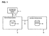
- FIG. 1 schematically shows an overall structure of an information processing system including a storage device system in accordance with an embodiment of the present invention.
- the information processing system of the present embodiment includes an information processing device 11, and at least a first storage device 10 and a second storage device 20.
- the first storage device 10 is equipped with a logical volume(s) 30 on which the first storage device performs data input/output processings (hereafter referred to as a "first logical volume(s)”)
- the second storage device 20 is equipped with a logical volume(s) 40 on which the second storage device performs data input/output processings (hereafter referred to as a "second logical volume(s)").
- the information processing device 11 and the first storage device 10 are communicatively connected to each other via a first network 50.
- the first network 50 may be, for example, a LAN (Local Area Network), a SAN (Storage Area Network), an iSCSI (Internet Small Computer System Interface), an ESCON (Enterprise Systems Connection) ®, or a FICON (Fibre Connection) ®.
- the first storage device 10 and the second storage device 20 are communicatively connected to each other via a second network 60.
- the second network 60 may be, for example, a Gigabit Ether Net ®, an ATM (Asynchronous Transfer Mode), or a public telephone line.
- the information processing device 11 may be a computer that is equipped with a CPU (Central Processing Unit), memories, and other devices.
- the information processing device 11 may be a personal computer, a work station or a mainframe computer.
- the information processing device 11 may be composed of a plurality of computers that are mutually connected.
- An operating system is operating on the information processing device 11, and application software is operating on the operating system.
- FIG. 2 shows a structure of a disk array device, which is described as an example of the first storage device 10 and the second and 20.
- the first and second storage devices 10 and 20 may be any appropriate devices, such as, for example, semiconductor storage devices.
- the disk array device 10 is equipped with various components including a channel control section 201, a remote communications interface 202, disk control sections 203, a shared memory 204, a cache memory 205, a switching control section 206 that is composed of cross bus switches that communicatively connect the components described above, a management terminal 207, and memory devices 208.
- the first and second storage devices 10 and 20 may have the same structure.
- the cache memory 205 is used to temporarily store data that is exchanged mainly between the channel control section 201 and the disk control sections 203. For example, when a data input/output command which the channel control section 201 receives from the information processing device 11 is a write command, the channel control section 201 writes in the cache memory 205 write data received from the information processing device 11. Also, an appropriate one of the disk control devices 203 reads the data written in the cache memory 205, and writes the same in the memory devices 208.
- the disk control section 203 reads a data I/O request stored in the shared memory 204 written by the channel control section 201, and executes data writing processing or data reading processing with respect to the memory devices 208 according to a command set at the data I/O request (for example, a command according to a SCSI standard).
- the disk control section 203 writes in the cache memory 205 data that has been read out from the memory devices 208.
- the disk control section 203 transmits to the channel control section 201 notifications, such as, for example, a data write completion notification and a data read completion notification.
- the disk control section 203 may be equipped with a function to control the memory devices 208 with RAID levels (for example, 0, 1, 5) stipulated in the so-called RAID (Redundant Array of Inexpensive Disks) method.
- the memory devices 208 may be, for example, hard disk devices.
- the memory devices 208 may be provided in one piece with or separately as independent devices from the disk array device.
- Storage regions provided by the memory devices 208 at each site are managed in units of logical volumes 209, which are volumes that are logically set on the storage regions. Data can be written in or read from the memory devices 208 by designating LUNs (Logical Unit Numbers) that are identifiers appended to the corresponding logical volumes 209.
- the logical volumes 209 are managed in units of a predetermined data amount such as units of 512 Kb, such that input and output of data in this predetermined unit are conducted.
- Each of the units is called a logical block, and each of the logical blocks is appended with a logical block address (hereafter referred to as a "LBA") that indicates positional information of the logical block.
- LBA logical block address
- the management terminal 207 may be a computer for maintaining and managing the disk array device and the memory devices 208. Changes in the software and parameters to be executed by the channel control section 201 and the disk control section 203 can be conducted by giving instructions from the management terminal 207.
- the management terminal 207 can be in a form that is built in the disk array device, or can be provided independently from the disk array device.
- the remote communications interface 202 is a communications interface (i.e., a channel extender) that is used for data transfer to another storage device. A copy of data is transferred in a remote copy operation to be descried below through this remote communications interface 202.
- the remote communications interface 202 converts the interface of the channel control section 201 (for example, an interface such as an ESCON ® interface or a FICON ® interface) to a communications method of the second network 60, whereby data transfer with the other storage device can be realized.
- the disk array device may have a structure that functions as a NAS (Network Attached Storage) configured to accept data input/output requests through designating file names from the information processing device 11 according to a relevant protocol such as a NFS (Network File System).
- NAS Network Attached Storage
- NFS Network File System
- the shared memory 204 can be accessed from both of the channel control section 201 and the disk control section 203.
- the shared memory 204 is used for delivering data input/output request commands, as well as for storing management information for the storage devices 10 and 20, and the memory devices 208.
- the shared memory 204 stores a LUN map information table 301 shown in FIG. 3, a command device management table 501 shown in FIG. 5, and a pair management table 1001 shown in FIG. 10.
- the logical volumes 209 are storage regions that are logically set on the physical volumes. Also, by using "virtual volumes” as logical volumes, the storage devices 10 and 20 on which the logical volumes 209 are set can be differentiated from other storage devices that are equipped with physical volumes correlated with the logical volumes 209.
- the first storage device 10 stores a LUN map information table 301 shown in FIG. 3.
- the LUN map information table 301 describes information relating to the logical volumes 209 that are handled by the first storage device 10.
- the LUN map information table 301 includes entries of "LUN,” “Target” and "Mapping LUN.”
- Each entry at "LUN” describes a LUN for each of the logical volumes.
- a logical volume 209 is a virtual volume
- a storage device that is equipped with the logical volume 209 correlated with the virtual volume is set at "Target.”
- a LUN of the logical volume 209 correlated with the virtual volume is set at "Mapping LUN.”
- Mapping LUN when there is a description at "Mapping LUN,” it means that the corresponding logical volume is a virtual volume.
- LUN map information table 301 may be registered, for example, by an operator through the management terminal 207 that is connected to the first storage device 10.
- the first storage device 10 uses the LUN map information table 301 described above and provides the second logical volume 40 of the second storage device 20 to the information processing device 11 by a mechanism to be described below as if the second logical volume 40 were the first logical volume 30 of the storage device 10.
- the information processing device 11 can make data input/output requests, which are to be issued to the logical volume 209 of the second storage device 20, to the first storage device 10.
- the information processing device 11 is equipped with a first write request section 401 that writes data in the first storage device 10 according to a first communications protocol. Upon receiving a data write request from the first write request section 401 (S401), the first storage device 10 writes in the cache memory 205 data to be written that has been received with the data write request.
- a data transfer section 402 of the first storage device 10 refers to the LUN map information table 301, and confirms as to whether or not a mapping LUN is set for a first logical volume 30 that is set in the data write request. If a second logical volume 40 is set as the mapping LUN, the data transfer section 402 transfers to a second write request section 403 a request to write the data in the second logical volume 40 according to a second communications protocol. In this embodiment, the second write request section 403 makes data write requests to the second storage device 20 according to the second communications protocol. The second storage device 20 receives the data write request from the second write request section 403, and writes the data in the second logical volume 40 (S402).
- first communications protocol and the second communications protocol are for example WRITE commands stipulated by a SCSI standard. Accordingly, the data write interfaces at the first storage device 10 and the second storage device 20 do not need to be changed.
- the information processing device 11 accesses the second logical volume as if the second logical volume were a logical volume on the first storage device 10.
- Each of the storage devices 10 and 20 is equipped with a "command device" for controlling special commands.
- the command device is used to convey commands from the information processing device 11 to the storage devices 10 and 20, and the storage devices 10 and 20 can execute commands that are stored in the command devices. What makes the special commands different from ordinary commands is that the command devices are the logical volumes 209. Functions of the command device will be described below.
- FIG. 5 shows a command device management table 501 that is stored in each of the storage devices 10 and 20.
- the command device management table 501 contains entries such as "Device” and "Command Device LUN.” Entries at "Device” indicate as to which of the storage devices 10 and 20 correspond to which of the command devices. Each entry at "Command Device LUN” sets a LUN of each logical volume 209 which expresses the entity of the corresponding command device.
- the command device management table 501 may be registered, for example, by an operator through the management terminal 207 that is connected to each of the storage devices 10 and 20.
- the command device management table 501 of each of the storage devices 10 and 20 can register command devices of other storage devices (that may be similar to the storage device 10 or 20).
- LUNs of virtual volumes which correspond to the LUNs of the command devices of the other storage devices are registered at the entries "Command Device LUN.”
- FIG. 6 shows an example of a command device interface 601, which is a data format of data that is written in a command device.
- the command device interface 601 is composed of a control parameter, an input parameter, and edited data.
- the control parameter is composed of a "process number" that indicates a command to be executed by a relevant storage device, and a "presence or absence of edited data” that indicates whether or not data is outputted as a result of the execution of the command.
- the input parameter sets parameter information that is used when executing the command.
- the edited data sets data that is outputted as a result of executing the command.
- the information processing device 11 is equipped with a command setting section 701 and a command transmission section 702.
- the command setting section 701 generates data that sets in a command interface 601 a "process number" of a command to be executed by the first storage device 10 and its "presence or absence of edited data.”
- the command transmission section 702 transmits to the first write request section 401 a request to write the data in a first logical volume, which is a command device of the first storage device 10, according to a first communications protocol.
- the first storage device 10 is equipped with a command execution section 703.
- the command execution section 703 is equipped with a pair management section 704, a copy forming section 705, a restore section 706, a journal storing section 707, a journal acquisition section 708 and a journal stop section 709, which control pairs of the logical volumes 209 to be described below.
- the command execution section 703 refers to a command device management table 501, and obtains a LUN of a command device that corresponds to the first storage device 10 (S701).
- the command execution section 703 refers to the command device (S702) and, if data in the form of the command device interface 601 exists, executes a command designated by a process number indicated in the data.
- the information processing device 11 sets a "process number" and a "presence or absence of edited data" in first data in the form of the command device interface 601 (S801). Then, the information processing device 11 refers to a command device management table 501 stored in the storage device 10, and obtains a LUN of a relevant command device of a storage device which executes the command. In order to write the created first data at the LUN obtained, the information processing device 11 transmits to the storage device 10 a write request designating the LUN (S802).
- the storage device 10 Upon receiving the write request, the storage device 10 writes the first data in the command device at the designated LUN.
- command devices are logical devices that are defined on storage areas of a plurality of storage devices, like the logical volumes 209, and write requests to the command devices are transmitted based on the same communications protocol as that for write requests transmitted to the logical volumes 209.
- the storage device 10 refers to the command device management table 501, to specify LUNs of command devices that the storage device 10 itself should refers to, and monitors whether or not the command devices have data written therein (S901).
- the storage device 10 executes the command designated by the process number in the first data (S902).
- the storage device 10 confirms whether edited data of the first data is present or absent (S903).
- edited data is absent, the storage device 10 deletes the first data from the command device (S906).
- the storage device 10 sets data outputted as a result of execution of the command as edited data (S904).
- the information processing device 11 confirms whether edited data for the command is present or absent (S803); and transmits to the storage device 10 a read request to read the edited data of the first data when the edited data is present (S804). Upon receiving the edited data from the storage device 10 (Yes at S805), the information processing device 11 completes the processing. It is noted that the read request is transmitted based on the same communications protocol for read requests for the logical volumes 209 other than the command device.
- the storage device 10 deletes the first data from the command device (S906).
- the information processing device 11 can transfer commands to the storage device 10.
- the information processing device 11 can transfer commands to the second storage device 20 through the first storage device 10, such that the second storage device 20 can execute the commands.
- the information processing device 11 when the information processing device 11 requests the storage device 10 and 20 to execute a "pair formation,” “journal acquisition,” “acquisition of processing state of journal,” “restore” or “swap” processing to be described below, the information processing device 11 uses the virtual volumes and command devices.
- FIG. 10 shows a pair management table 1001.
- a column of "COPY SOURCE DEVICE” indicates storage devices (10 or 20) to which those of the logical volumes of copy sources belong (hereafter referred to as "primary volumes”).
- a column of "COPY DESTIANTION DEVICE” indicates storage devices (10 or 20) to which those of the logical volumes of copy destinations belong (hereafter referred to as "auxiliary volumes”).
- a column of "PRIMARY LUN” indicates LUNs of the corresponding primary volumes
- a column of "AUXILIARY LUN” indicates LUNs of the corresponding auxiliary volumes.
- Each correspondence between a primary volume and an auxiliary volume is called a "pair.”
- Those of the logical volumes 209 for storing journals are assigned to the primary volumes and auxiliary volumes.
- a column of "PRIMARY JOURNAL LUN” sets LUNs of the logical volumes 209 of the journals assigned for the primary volumes (hereafter referred to as “primary journals”).
- a column of "AUXILIARY JOURNAL LUN” sets LUNs of the logical volumes 209 of the journals assigned for the auxiliary volumes (hereafter referred to as "auxiliary journals”).
- Any one of appropriate methods for assigning the logical volumes 209 for storing the journals can be used.
- the user himself/herself may designate those of the logical volumes 209 to be used as the journals, or the information processing device 11 may select appropriate unused ones of the logical volumes 209.
- the first storage device 10 is equipped with a third logical volume and a fifth logical volume
- the second storage device 20 is equipped with a fourth logical volume and a sixth logical volume.
- the information processing device 11 transmits a command to the first storage device 10 and the second storage device 20 for forming a pair of the third logical volume as being a primary volume and the fourth logical volume as being an auxiliary volume, and a pair of the fifth logical volume as being a primary journal and the sixth logical volume as being an auxiliary journal (S1101, S1102).
- the pair management sections 704 of the first and second storage devices 10 and 20 store information indicating the states of the pairs in the pair management tables 1001 of the respective storage devices 10 and 20.
- the copy forming section 705 of the second storage device 20 transmits to the first storage device 10 a read request to read data in the primary volume; and upon receiving from the first storage device 10 a copy of the data in the primary volume, the second storage device 20 writes the data in the auxiliary volume (S1103).
- the data in the primary volume and the data in the auxiliary volume can be matched with each other.
- a processing that brings the primary volume in conformity with the auxiliary volume by a pair forming instruction is called a "initial copy" processing.
- journal storage section 707 of the first storage device 10 starts a processing to obtain a copy of the data written in the primary volume and its positional information in the primary journal.
- the correlation between the primary volume and the primary journal is described hereunder with reference to FIG. 12.
- the primary journal is composed of a meta data region 1201 and a journal data region 1202.
- the journal storage section 707 of the first storage device 10 stores a copy of the data written in the primary volume (hereafter referred to as "journal data") in the journal data region 1202.
- journal storage section 707 of the first storage device 10 stores in the meta data region 1201 the time when data 1203 is updated in the primary volume, LBA(s) 1204 of the data 1203, LBA(s) 1206 of the corresponding journal data region, and the data length of the updated data.
- the auxiliary journal is composed of a meta data region 1201 and a journal data region 1202 like the primary journal.
- a copy of data in the logical volume 209 of the second storage device 20 can be stored in the logical volume 209 of the first storage device 10 by an instruction from the information processing device 11.
- a storage device at a remote site transmits a read request to a storage device at a primary site to thereby perform a copy forming processing.
- the storage device at the primary site needs to write the data in the storage device at the remote site after it confirms that the storage device at the remote site is ready for forming a pair. For this reason, the processing load on the storage device at the primary site becomes heavier, which would affect the overall performance of the primary site that is performing other primary processings.
- the processing load at the storage device at the primary site can be alleviated.
- the first storage device 10 accepts write requests from the information processing device 11, and updates the data in the primary volumes. For this reason, the data in the primary volumes becomes inconsistent with the data in the auxiliary volumes.
- the primary journal stores journal data for executions performed even after the copy forming processing took place.
- the second storage device 20 copies data stored in the primary journal into the auxiliary journal, and writes the data stored in the auxiliary journal into the auxiliary volumes, such that updates of the data on the primary volumes can be likewise performed on the auxiliary volumes.
- a processing to copy data stored in the primary journal into the auxiliary journal by the second storage device 20 is referred to as a "journal acquisition” processing
- a processing to write journal data stored in the auxiliary journal into the auxiliary volume is referred to as a "restoration” processing.
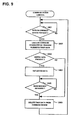
- FIG. 13 shows a flowchart of the journal acquisition processing.
- the information processing device 11 transmits a journal acquisition instruction to the second storage device 20 (S1301).
- the journal acquisition section 708 of the second storage device 20 refers to the pair management table 1001, and obtains a primary journal LUN of the corresponding pair.
- the journal acquisition section 708 of the second storage device 20 transmits to the first storage device 10 a read request to read the primary journal.
- the journal acquisition section 708 of the second storage device 20 writes the data in the auxiliary journal (S1302).
- the information processing device 11 transmits to the second storage device 20 a restore instruction to restore data in the auxiliary journal onto the auxiliary volumes (S1401).
- the restore section 706 of the second storage device 20 writes journal data stored in the auxiliary journal into the auxiliary volumes (S1402).
- FIG. 15 shows journal data regions 1202 for the primary journal and the auxiliary journal.
- the journal data regions for the primary journal and the auxiliary journal are defined by the same head LBA and end LBA, respectively.
- the journal data region 1202 for the primary journal is composed of journal storage completed regions 1502, 1503 and 1504 which store journal data, and purge completed regions 1501 which do not store journal data.
- the journal data region 1202 of the auxiliary journal is composed of restoration completed regions 1521 that store journal data that have already been used for restoration in the auxiliary volumes, restore in-progress region 1522 that stores journal data that are designated for restoration, read completed region 1523 that stores journal data that are not designated for restoration, and read in-progress region 1524 that stores journal data that are being read from the primary journal in response to a journal acquisition instruction.
- Each of the storage devices 10 and 20 stores journal data in the journal data region 1202 from the head LBA to the end LBA in a chronological order as the journal data is created.
- each of the storage devices 10 and 20 returns to the head LBA again, and stores journal data from there.
- the storage devices 10 and 20 use the journal data regions cyclically between the head LBA and the end LBA.
- the first storage device 10 that is equipped with the primary journal stores a journal-out LBA 1511 which is a head LBA of the journal storage completed regions 1502, 1503 and 1504, and a journal-in LBA 1512 which is a head LBA of the purge completed region 1501.
- journal-out LBA and the journal-in LBA are equal to each other, it means that journal data is not stored in the primary journal.
- the second storage device 20 that is equipped with the auxiliary journal stores a restoration completed LBA 1531 which is the highest LBA of the restoration completed region 1521, a to-be restored LBA 1532 which is the highest LBA of the restore in-progress region 1522, a read completed LBA 1533 which is the highest LBA of the read completed region 1523, and a to-be read LBA 1534 which is the highest LBA of the read in-progress region 1524.
- restoration completed LBA 1531 and the to-be restored LBA 1532 are equal to each other, it means that a restoration processing instructed by the information processing device 11 has been completed.
- read completed LBA 1533 and the to-be read LBA 1534 are equal to each other, it means that a journal acquisition processing instructed by the information processing device 10 has been completed.
- the information processing device 11 can transmit to the first storage device 10 and the second storage device 20 a request to obtain the processing state of journal.
- Each of the storage devices 10 and 20 confirms the states of LBAs that indicate the boundaries of the regions described above, and responds to the request.
- the processing to release a region is called a "purge" processing.
- Each of the storage devices 10 and 20 can perform a purge processing by changing addresses of LBAs that indicate the boundaries of the regions.
- the first storage device 10 can purge the journal storage completed region 1502, among the journal storage completed regions 1502, 1503 and 1504 of the primary journal, which the second storage device 20 has completed acquiring the journal data into the auxiliary journal.
- the first storage device 10 changes the journal-out LBA 1511 to the head LBA of the journal storage completed region 1503, such that the journal storage completed region 1502 becomes the purge completed region 1501.
- the second storage device 20 treats the restoration completed region 1521 of the auxiliary journal as a region that is purged, and stores the journal data obtained in response to the journal acquisition instruction in the restoration completed region 1521.
- the information processing device 11 transmits to the first storage device 10 a request to obtain the processing status of the primary journal (S1601).
- the information processing device 11 transmits to the first storage device 10 a read request to read edited data of a command device at which the processing status of the primary journal is set (S1602).
- the information processing device 11 Upon receiving the edited data of the command device from the first storage device 10 (S1603), the information processing device 11 transmits to the second storage device 20 a journal acquisition request to obtain journal data starting at the journal-out LBA 1511 to a LBA immediately before the journal-in LBA 1512 (S1604).
- the information processing device 11 transmits to the second storage device 20 a request to obtain the processing status of the auxiliary journal (S1605).
- the information processing device 11 transmits to the second storage device 20 a read request to read edited data of a command device at which the processing status of the auxiliary journal is set (S1606).
- the information processing device 11 compares the read completed LBA 1533 and the to-be read LBA 1534 set in the edited data, to confirm whether or not acquisition of the journal data has been completed (S1608).
- the information processing device 11 transmits to the second storage device 20 a restore request to restore journal data up to the read completed LBA 1533 (S1609).
- the information processing device 11 transmits to the first storage device 10 a purge request to purge the journal data up to the read completed LBA 1533 (S1610).
- the information processing device 11 repeats the journal acquisition processing and restoration processing.
- updated data in a storage device at a primary site can be reflected on a storage device at.a remote site without performing data communications between multiple information processing devices, and without adding new commands to the operating system of the information processing devices. It is noted that, with an instruction from the information processing device 11 that is communicatively connected to a storage device at a remote site, the storage device at the remote site can obtain journal data from a storage device at a primary site and restore the data.
- a primary volume of the first storage device 10 and an auxiliary volume of the second storage device 20 form a pair by an instruction from an information processing device 11 (hereafter referred to as a "first information processing device") that is communicatively connected to the first storage device 10.
- an information processing device 11 hereafter referred to as a "second information processing device” that is communicatively connected to the second storage device 20 can continue processings that have been performed by the first information processing device, using the auxiliary volume of the pair.
- the second information processing device switches the relation between the primary volume and the auxiliary volume.
- a pair is formed with the logical volume 209 of the second storage device 20 being a primary volume and the logical volume 209 of the first storage device 10 being an auxiliary volume.
- Such a processing to switch the pair relation is called a "swap" processing.
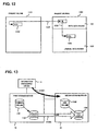
- the second information processing device 11 transmits a pair swap instruction to the first storage device 10 and the second storage device 20 (S1701, S1702).
- the journal stop section of the first storage device 10 stops storing journals in the primary volume.
- the pair management section 704 of the first storage device 10 swaps the primary volume and the auxiliary volume registered in the pair management table 1001.
- the pair management section 704 of the second storage device 20 swaps the primary volume and the auxiliary volume registered in the pair management table 1001.
- the journal storage section 707 of the second storage device 20 starts storing journals of the logical volume 209 of the second storage device 20, which defines the primary volume.
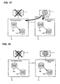
- FIG. 18 shows a state in which a pair is formed with the logical volume 209 of the second storage device 20 being the primary volume and the logical volume 209 of the first storage device 10 being the auxiliary volume, as a result of the swap processing performed by the first storage device 10 and the second storage device 20 which received the pair swap instruction.
- the swap processing performed by the second information processing device 20 and the storage devices 10 and 20 will be described in detail with reference to flowcharts in FIGS. 19 through 21.
- the second information processing device executes the journal acquisition processing and the restoration processing described above (S1901).
- the second information processing device transmits to the second storage device 20 a request to obtain the processing status of the auxiliary journal (S1902).
- the second information processing device transmits to the second storage device 20 a read request to read edited data of a command device in which the processing status of the auxiliary journal is set (S1903).
- the second information processing device Upon receiving the edited data of the command device from the second storage device 20 (S1904), the second information processing device compares the restoration completed LBA 1531 and the to-be restored LBA 1532 set in the edited data, to confirm if the restoration processing has been completed (S1905). If the restoration has been completed, the second information processing device transmits a pair swap request to the first storage device 10 and the second storage device 20 (S1906, S1907).
- the first storage device 10 stops its journal acquisition processing with respect to the primary volume (S2001), and swaps the relation between the copy source and the copy destination registered in the pair management table 1001 (S2002). Also, the second storage device 20, that has received the pair swap request, swaps the relation between the copy source and the copy destination registered in the pair management table 1001 (S2101), and starts a journal acquisition processing with respect to the primary volume of the second storage device 20 (S2102).
- the primary site is equipped with a first information processing device and a first storage device 10
- the remote site is equipped with a second information processing device and a second storage device 20.
- the second information processing device uses the second storage device 20 to continue primary processings performed at the primary site.
- the second information processing device may instruct the first storage device 10 and the second storage device 20 to execute the swap instruction described above, such that the second storage device 20 is used for the primary processings, and data on the second storage device 20 can be stored as a backup in the first storage device 10.
- the execution of the primary processings can be quickly switched to the primary site, when the first information processing device is recovered from the failure.
- pair swap instructions from the information processing device 11 to the storage devices 10 and 20 are provided using read/write commands with which the information processing device 11 is equipped, there is no need to add new commands to the operating system on the information processing device 11.
- the storage device system described above transfers commands between two storage devices using virtual volumes and command devices. Furthermore, a virtual volume structure can be set up among three or more storage devices so that commands can be transferred among three or more storage devices.
- FIG. 22 shows a storage device system in accordance with an embodiment of the present invention, which includes, for example, a first storage device 10, a second storage device 20 and a third storage device 25.
- a logical volume 2201 of the first storage device 10 is a virtual volume of a logical volume 2202 of the second storage device 20
- the logical volume 2202 of the second storage device 20 is a virtual volume of a logical volume 2203 of the third storage device 25.
- a third logical volume 2203 is a command device.
- FIG. 23 indicates the storage device system.
- the first storage device 10, the second storage device 20 and the third storage device 25 are equipped with logical volumes 2301, 2302 and 2303, respectively.
- the logical volume 2301 of the first storage device 10 and the logical volume 2302 of the second storage device 20 form a synchronous pair with the logical volume 2301 of the first storage device as being a primary logical volume.
- FIG. 24 indicates a synchronous pair management table 2401.
- the synchronous pair management table 2401 is equipped with entries of "COPY SOURCE DEVICE,” “COPY DESTINATION DEVICE,” “PRIMARY LUN,” and "AUXILIARY LUN.”
- the first storage device 10 is set as a copy source device, the second storage device 20 as a copy destination device, a LUN of the logical volume 2301 of the first storage device 10 as a primary LUN, and a LUN of the logical volume 2302 of the second storage device 20 as an auxiliary LUN.
- the first storage device 10 Upon receiving a data write request from the information processing device 11 to write data in the logical volume 2301 of the first storage device 10, which is a primary volume, the first storage device 10 refers to the synchronous pair management table 2401, and sends the data write request to the second storage device 20 to write the data in the logical volume 2302 of the second storage device 20, which is an auxiliary volume corresponding to the primary volume.
- the first storage device 10 Upon receiving a data write completion notification for the data write request from the second storage device 20, the first storage device 10 sends the data write completion notification to the information processing device 11. In other words, when the write completion notification is sent to the information processing device 11, the same data have been written in the primary volume and the auxiliary volume.
- a synchronous pair is formed when the first storage device 10 and the second storage device 22 are located in a short distance from each other, and a pair using the journals described above (hereafter referred to as an "asynchronous pair") is formed with the second storage device 20 and the third storage device 25.
- the information processing device 11 sends to the second storage device 20 and the third storage device 25 a command to form a pair with the logical volume of the second storage device 20 being as a primary volume and the logical volume of the third storage device 25 as being an auxiliary volume, using the virtual volumes and command devices.
- the information processing device 11 sends a command to obtain and restore a journal in the pair to the third storage device 25, by using the virtual volumes and the command devices.
- data of the first storage device 10 can be backed up in the third storage device 25 that may be installed at a great distance from the first storage device 10.
- neither the third storage device 25 nor the second storage device 20 that is located intermediate between the first and third storage devices 10 and 25 requires an information processing device. It is noted that an information processing device for backup may be connected to the third storage device 25, and processings may be continued using data in the third storage device 25 when the first storage device 10 fails.
- the information processing device 11 sends commands to the storage devices 10, 20 and 25.
- each of the storage devices 10, 20 and 25 may be equipped with a command setting section 701 and a command transmission section 702.
- the first storage device 10 can send a command to be executed at the third storage device 25 to the command device of the third storage device 25 via the virtual volume of the second storage device 20.
- the first storage device 10 can send to the third storage device 25 a command to confirm the status of the third storage device 25, such that the first storage device 10 can detect the status, such as, a failure of the third storage device 25. If a failure occurs in the third storage device 25, the first storage device 10 can send to the second storage device 20 and the third storage device 25 a command to cancel the above-described asynchronous pair between the second storage device 20 and the third storage device 25.
- FIG. 25 indicates a path information management table 2501 that is stored in the information processing device 11.
- the path information management table 2501 includes columns of "DEVICE” and "PATH.”
- addresses of the storage devices 10 and 20 are stored.
- an address may be information that is composed of a product serial number, a port number and the like of each of the storage devices 10 and 20.
- the "PATH" column stores information indicating as to how each of the storage devices 10 and 20 is connected to the information processing device. For example, according to the path information management table 2501 shown in FIG.
- the path to the first storage device 10 is indicated as being "DIRECT” and the path to the second storage device 20 is indicated as being "FIRST.” This means that the information processing device 11 is directly connected to the first storage device 10, and is connected to the second storage device 20 through the first storage device 10.
- FIG. 26 shows a command interface 2601 which is a data format used when transferring a command from the information processing device 11 to the storage devices 10 and 20.
- the command interface 2601 is composed of an identification number, a transfer destination parameter, a control parameter and an input parameter.
- the identification number is a number for identifying the data, which is appended by the information processing device 11 when generating the data. Addresses of the storage devices 10 and 20 to which the data is sent are set at the transfer destination parameter.
- the control parameter and the input parameter set parameters similar to those of the command device interface 601 that is used in the command device.
- the information processing device 11 is equipped with a data generation section 2701 and a data transfer section 2702.
- Each of the storage devices 10 and 20 is equipped with a command analysis section 2703, a data transfer section 2704 and a command execution section 2705.
- the data generation section 2701 of the information processing device 11 refers to the path information management table 2501, refers to the path to the second storage device 20, and recognizes that the second storage device 20 is connected via the first storage device 10.
- the data generation section 2701 generates data 2710 in the command interface 2601 format in which the address of the second storage device 20 is set as a transfer destination address and a first command is set at a process number.
- the data generation section 2701 notifies the data transfer section 2702 to transfer the data 2710 to the first storage device 10.
- the data transfer section 2702 transfers the data 2710 to the first storage device 10.
- the command analysis section 2703 of the first storage device 10 upon receiving the data 2710, notifies the data transfer section 2704 of the first storage device 10 to transfer the data 2710 to the second storage device 20 that is set as the transfer destination address.
- the data transfer section 2704 of the first storage device 10 generates data 2711 by deleting the transfer destination parameter from the data 2710, and transfers the data 2711 to the second storage device 20.
- the command analysis section 2703 of the second storage device 20 upon receiving the data 2711, obtains the first command from the command parameter, as the data 2711 does not contain a transfer destination parameter.
- the command analysis section 2703 of the second storage device 20 notifies the command execution section 2705 of the second storage device 20 to execute the first command.
- the command execution section 2705 of the second storage device 20 upon receiving the notification from the command analysis section 2703, executes the first command.
- the command execution section 2705 of the second storage device 20 stores the output result as edited data 2712.
- the same identification number is appended to all of the data 2710, 2711 and 2712.
- the information processing device 11 can obtain the output result of the first command by designating an identification number at the first storage device 10 and sending a send command to send the edited data 2712.
- FIG. 28 shows a flow of processings to transfer a command among three storage devices, i.e., the first storage device 10, the second storage device 20 and the third storage device 25.
- the information processing device 11 is communicatively connected to the first storage device 10, the first storage device 10 is communicatively connected to the second storage device 20, and the second storage device 20 is communicatively connected to the third storage device 25.
- the path information management table 2501 of the information processing device 11 sets paths indicated in FIG. 29.
- the data generation section 2701 of the information processing device 11 refers to the path information management table 2501 and recognizes that the third storage device 25 is connected via the first storage device 10 and the second storage device 20.
- the data generation section 2701 generates data 2801 in the command interface 2601 format in which the second storage device 20 and the third storage device 25 are set as transfer destination addresses, and a first command is set as a process number.
- the data generation section 2701 notifies the data transfer section 2702 to transfer the generated data to the first storage device 10 that is at the head address in the transfer path.
- the data transfer section 2702 upon receiving the notification, sends the data 2801 to the storage device 10.
- the command analysis section 2703 of the first storage device 10 upon receiving the data 2801, obtains the address of the second storage device 20 which is set at the head of the transfer destination parameter, and notifies the data transfer section 2704 of the first storage device 10 to send the data to the second storage device 20.
- the data transfer section 2704 upon receiving the notification, generates data 2808 by deleting the transfer destination address of the second storage device 20 from the data 2801, and sends the data 2802 to the second storage device 20.
- the second storage device 20 obtains the address of the third storage device 25 which is set at the head of the transfer destination parameter just as does the first storage device 10, generates data 2803 by deleting the third storage device 25 from the transfer destination parameter, and sends the data 2803 to the third storage device 25.
- the command analysis section 2703 of the third storage device 25 upon receiving the data 2803, obtains the process number of the first command from the control parameter as the data 2803 does not contain a transfer destination address, and notifies the command execution section 2705 of the third storage device 25 to execute the first command.
- a command can be transferred among three or more storage devices.
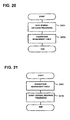
- FIG. 30 shows a flowchart of processings executed by the information processing device 11 when a command is transferred with a transfer destination address being designated.
- the information processing device 11 generates an identification number and sets the identification number in a command interface 2601 (S3001).
- the identification number can be any number that can uniquely identify the command interface 2601 generated.
- the information processing device 11 refers to the path information management table 2501, and obtains a path for a storage device to which a command is to be transferred (S3002).
- the information processing device 11 sets one or multiple transfer destination addresses at the transfer destination parameter based on the path information obtained (S3003).
- the information processing device 11 sets a process number of the command to be executed by the storage device at the transfer destination and a presence/absence of edited data of the command (S3004).
- the information processing device 11 sends the data of the command interface 2601 to a storage device at the head address in the transfer path (S3005).
- the information processing device 11 confirms whether the command results in edited data (S3006), and ends the processing when no edited data exists.
- the information processing device 11 designates the identification number and sends an edited data send request to the storage device at the head address in the transfer path (S3007).
- the information processing device 11 waits until it receives the edited data (S3008), and ends the processing upon receiving the edited data.
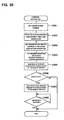
- FIG. 31 shows a flowchart of processings performed at the storage devices 10, 20 and 25, when a command is transferred with a transfer destination address being designated.
- Each of the storage devices 10, 20 and 25 may perform the following processings.
- each storage device Upon receiving the data of the command interface (S3101), each storage device stores the data in a cache memory (S3102). The storage device confirms whether the data contains a transfer destination parameter (S3103). If the transfer destination parameter exists, the storage device obtains a transfer destination address at the head of the transfer destination parameter (S3104). Next, the storage device deletes the transfer destination address at the head of the transfer destination parameter from the data (S3105), and sends the data to the transfer destination address previously obtained (S3106). The storage device confirms whether the command results in edited data (S3107).
- the storage device executes a processing to obtain the edited data (S3108), deletes the data from the cache memory (S3109), and ends the processing. If no edited data exists, the storage device does not perform the processing to obtain edited data, deletes the data from the cache memory (S3109), and ends the processing.
- the storage device When a transfer destination parameter is not set in the received command interface 2601, the storage device (which may be 10, 20 or 25) obtains a process number of the control parameter (S3110), and executes a command designated by the process number (S3111). The storage device (10, 20, 25) confirms whether the command results in edited data (S3112). If edited data exists, the storage device (10, 20, 25) generates edited data set with the identification number set in the command interface 2601 (S3113), executes a process to obtain edited data (S3108), deletes the data from the cache memory (S3109), and ends the processing. If edited data does not exist, the storage device (10, 20, 25) deletes the data from the cache memory (S3109) and ends the processing.
- FIG. 32 shows a flowchart of the processing to obtain edited data performed by the storage device (10, 20, 25).
- the storage device (10, 20, 25) waits until it receives a edited data obtaining request to obtain edited data (S3201). Upon receiving the request to obtain edited data, the storage device refers to the command interface 2601 at the identification number that is sent in the edited data obtaining request (S3202). The storage device (10, 20, 25) confirms if the command interface 2601 referred to contains a transfer destination parameter (S3203). If the transfer destination parameter exists, it is not the storage device (10, 20, 25) that executed the command, such that the storage device (10, 20, 25) obtains a transfer destination address at the head of the transfer destination parameter (S3204), and sends the edited data obtaining request to the obtained transfer destination address (S3205).
- S3203 transfer destination parameter
- the storage device (10, 20, 25) waits until it receives edited data (S3206), and, when it receives the edited data, the storage device sends the edited data received to the transmission source of the edited data obtaining request (S3207).
- the storage device (10, 20, 25) obtains edited data of the identification number (S3208), and sends obtained edited data to the transmission source of the edited data obtaining request (S3209).
- the edited data is sent to the information processing device 11 back along the path in which the command is transferred.
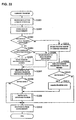
- FIG. 33 and FIG. 34 show flowcharts of processings performed in this situation by the storage device (10, 20, 25).
- FIG. 33 indicates processings performed by the storage device (10, 20, 25) as it receives the command interface 2601, and its basic process flow is generally the same as the process flow indicated in FIG. 31.
- the process flow indicated in FIG. 33 differs from the process flow in FIG. 31 in that the storage device (10, 20, 25) that has received the data of the command interface 2601 needs to judge as to whether the storage device itself is in a transfer path or whether the storage device should execute a command.
- the storage device (10, 20, 25) confirms whether the last transfer destination address is the address of its own (S3303), and determines that the storage device (10, 20, 25) is in a transfer path if the last transfer destination address is not its own address, and determines that the storage device (10, 20, 25) should execute a command if the last transfer destination address is its own address.
- the storage device confirms whether the transfer destination address includes its own address (S3304); if its own address is included, the storage device obtains a transfer destination address next to the address of its own (S3305); and if its own address is not included, the storage device obtains the head transfer destination address (S3306).
- the storage device (10, 20, 25) sends the data of the command interface 2601 to the obtained transfer destination address (S3307).
- the storage device (10, 20, 25) obtains a process number of the control parameter (S3311), and executes a command designated by the process number (S3312).
- Other processings are basically the same as those of the processings indicated in FIG. 31 except an edited data obtaining process (S3309).
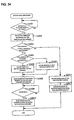
- FIG. 34 shows a flowchart of the edited data obtaining process performed when the transfer destination address is not deleted.
- the edited data obtaining process in FIG. 34 differs from the process indicated in FIG. 31 in that the storage device that has received an edited data obtaining request needs to judge whether the storage device (10, 20, 25) itself is in a transfer path or whether the storage device (10, 20, 25) itself has executed the command.
- the storage device (10, 20, 25) judges by the same method indicated in FIG.
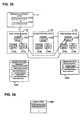
- FIG. 35 shows a flowchart of processings performed when the first storage device 10 receives data 3501 of a command interface from the information processing device 11.
- the shared memory 204 of the first storage device 10 stores a connection information management table 3601 indicated in FIG. 36.
- the connection information management table 3601 can be set by a system administrator through the management terminal 207.
- the connection information management table 3601 stores addresses of the storage devices 10 and 20 that are connected. For example, the connection information management table 3601 in FIG. 36 indicates that the first storage device 10 is connected to the second storage device 20 and the third storage device 25.
- the first storage device 10 upon receiving the data 3501 of the command interface from the information processing device 11, refers to the connection information management table 3601, and obtains the address of the third storage device 25 which is set at the last of the transfer destination parameter.
- the first storage device 10 judges that data can be directly sent to the third storage device 25 because the address of the third storage device 25 is stored in the connection information management table 3601.
- the first storage device 10 generates data 3502 by deleting the transfer destination addresses of the third storage device 25 and the second storage device 20, and directly sends the data 3502 to the third storage device 25 without passing it through the second storage device 20.
- FIG. 37 shows a flowchart of processings in which the storage device (which may be 10, 20 or 25) determines the shortest path and transfers data of a command interface, which differs from the processing indicated in FIG. 31 only in that the storage device (10, 20, 25) judges the shortest transfer path.
- the storage device which may be 10, 20 or 25
- the storage device (10, 20, 25) obtains the number of transfer destination addresses set in the transfer destination parameter, and sets the obtained number as a variable "N" (S3704). Then, the storage device (10, 20, 25) obtains the N-th transfer destination address (S3705), and confirms whether the obtained transfer destination address is stored in the connection information management table 3601 (S3706). When the obtained transfer destination address is not stored in the connection information management table 3601, the number N is reduced by 1 (S3707), and the storage device (10, 20, 25) repeats the processings to obtain the N-th transfer destination address and to confirm whether the obtained transfer destination address is stored in the connection information management table 3601 (S3705, S3706). As a result, the storage device (10, 20, 25) can obtain the shortest transfer path.
- the storage device (10, 20, 25) deletes the transfer destination addresses before the N-th transfer destination address from the data of the command interface 2601 (S3708), and sends the data to the N-th transfer destination address.
- the other processings are the same as those indicated in FIG. 31.
- the edited data obtaining process (S3711) is the same as the process in FIG. 32.
- the storage device (10, 20, 25) determines the shortest transfer path, and transfers a command along the shorted transfer path, such that the data transfer amount among the storage devices can be reduced, and the transfer time for transferring commands can be shorted.
- FIG. 38 indicates a command interface 3801 for sending commands to a plurality of storage devices 10, 20 and 25.
- the command interface 3801 has a structure in which a plurality of command interfaces 2601 shown in FIG. 26 are connected.
- FIG. 39 shows an example of processings in which the information processing device 11 sends a first command to the second storage device 20 and a second command to the third storage device 25.
- the information processing device 11 sets the second storage device 20 at the transfer destination address of the first transfer destination parameter, and the first command at the process number of the first control parameter.
- the information processing device 11 sets the third storage device 25 at the transfer destination address of the second transfer destination parameter, and the second command at the process number of the second control parameter.
- the information processing device 11 sends data 3901 thus generated to the first storage device 10 that is located at the head of the transfer path.
- the first storage device 10 upon receiving the data 3901, obtains the transfer destination address of the first transfer destination parameter, and sends data 3092 by deleting the head transfer destination parameter from the data 3901 to the second storage device 20.
- the second storage device 20 upon receiving the data 3902, executes the first command that is set in the first control parameter. Then the second storage device 20 deletes the head control parameter in the data 3902, and obtains the transfer destination address of the transfer destination parameter.
- the second storage device 20 sends to the third storage device 25 data 3903 by deleting the head transfer destination parameter from the data 3902.
- the third storage device 25 upon receiving the data 3903, executes the second command set in the head control parameter.
- FIG. 40 shows a flowchart of processings performed by the first information processing device 11 when sending commands to a plurality of storage devices 10, 20 and 25.
- the information processing device 11 refers to the path information management table 2501, and obtains paths to the storage devices 10, 20 and 25 to which the commands are sent (S4001). Then, the information processing device 11 repeats executions to set a transfer destination address in the transfer destination parameter (S4002) and to set a command in the control parameter (S4003) in the order from the head storage device 10 to the storage devices 20 and 25 in the path until there is no transfer destination remained (S4004).
- the information processing device 11 sends the data of the command interface 3801 thus generated to the head storage device 10 and the storage devices 20 and 25 in the transfer path (S4005).
- FIG. 41 shows a flowchart of processings performed at each of the storage devices 10, 20 and 25 when commands are sent to the plurality of storage devices 10, 20 and 25.
- the storage device (which may be 10, 20 or 25), upon receiving data of the command interface 3801 (S4101), stores the data in the cache memory (S4102).
- the storage device (10, 20, 25) confirms whether the head of the data is a transfer destination parameter (S4103). If the head of the data is a transfer destination parameter, the storage device (10, 20, 25) obtains a transfer destination address of the head transfer destination parameter (S4104), deletes the head transfer destination parameter from the data (S4105), and sends the data to the obtained transfer destination address (S4106).
- the storage device (10, 20, 25) When the head of the data is not a transfer destination parameter, the storage device (10, 20, 25) obtains a process number of the head control parameter (S4107), and executes a command designated by the process number (S4108). The storage device (10, 20, 25) deletes the head control parameter (S4109), and confirms whether a further transfer destination parameter exists (S4110). When the further transfer destination parameter exists, the storage device (10, 20, 25) performs processings from obtaining a transfer destination address to sending data to the transfer destination address (S4104 - S4106).
- the information processing device 11 can perform controls, such as, simultaneously sending pair forming commands to the storage devices 10, 20 and 25 that form primary volumes and to the storage devices 10, 20 and 25 that form auxiliary volumes in asynchronous pairs.
- pairs can be readily formed without communicating among plural information processing devices.
- commands are transferred through designating transfer destination addresses.
- the information processing device 11 sends commands to the storage devices 10, 20 and 25.
- each of the storage devices 10, 20 and 25 may be equipped with a data generation section 2701 and a data transmission section 2702.
- commands can be executed by each of the storage devices 10, 20 and 25 which may not be connected to an information processing device, just as does the storage device system transfer commands through using virtual volumes and command devices.
- data backup and pair operations can be conducted without communicating data among multiple information processing devices.
- commands are transferred through designating transfer destination addresses, dedicated logical volumes such as command devices do not need to be provided, and therefore data areas to be allocated to users would not be reduced.
- command devices there is a possibility that the performance of the storage devices 10, 20 and 25 may lower because data input/output requests may concentrate on specified logical volumes.
- cache memories are used, such that a reduction in the performance of the storage devices 10, 20 and 25 can be prevented.
- commands that are transferred are commands relating to pairs of logical volumes.
- commands to be transferred are not limited to commands relating to pairs, but may be any commands that are executable by the storage devices 10, 20 and 25.
Landscapes
- Engineering & Computer Science (AREA)
- Theoretical Computer Science (AREA)
- Physics & Mathematics (AREA)
- General Engineering & Computer Science (AREA)
- General Physics & Mathematics (AREA)
- Human Computer Interaction (AREA)
- Quality & Reliability (AREA)
- Computer Networks & Wireless Communication (AREA)
- Information Retrieval, Db Structures And Fs Structures Therefor (AREA)
- Signal Processing For Digital Recording And Reproducing (AREA)
Applications Claiming Priority (3)
| Application Number | Priority Date | Filing Date | Title |
|---|---|---|---|
| JP2003325082 | 2003-09-17 | ||
| JP2003400513A JP4598387B2 (ja) | 2003-09-17 | 2003-11-28 | 記憶システム |
| EP04253882A EP1517241A3 (fr) | 2003-09-17 | 2004-06-29 | Dispositif de contrôle d'un disque dur à distance avec fonction de transmission de commandes à un dispositif de stockage éloigné. |
Related Parent Applications (2)
| Application Number | Title | Priority Date | Filing Date |
|---|---|---|---|
| EP04253882A Division EP1517241A3 (fr) | 2003-09-17 | 2004-06-29 | Dispositif de contrôle d'un disque dur à distance avec fonction de transmission de commandes à un dispositif de stockage éloigné. |
| EP04253882.7 Division | 2004-06-29 |
Publications (3)
| Publication Number | Publication Date |
|---|---|
| EP1669873A2 true EP1669873A2 (fr) | 2006-06-14 |
| EP1669873A3 EP1669873A3 (fr) | 2010-08-25 |
| EP1669873B1 EP1669873B1 (fr) | 2014-10-01 |
Family
ID=34197206
Family Applications (4)
| Application Number | Title | Priority Date | Filing Date |
|---|---|---|---|
| EP05006107A Withdrawn EP1560108A3 (fr) | 2003-09-17 | 2004-06-29 | Dispositif de contrôle d'un disque dur à distance avec fonction de transmission de commandes à un dispositif de stockage éloigné |
| EP04253882A Withdrawn EP1517241A3 (fr) | 2003-09-17 | 2004-06-29 | Dispositif de contrôle d'un disque dur à distance avec fonction de transmission de commandes à un dispositif de stockage éloigné. |
| EP05009878A Ceased EP1562106A3 (fr) | 2003-09-17 | 2004-06-29 | Dispositif de contrôle d'un disque dur à distance avec fonction de transmission de commandes à un dispositif de stockage éloigné |
| EP06005247.9A Expired - Lifetime EP1669873B1 (fr) | 2003-09-17 | 2004-06-29 | Dispositif de contrôle de disque de stockage à distance avec fonction de transfert de commandes vers des dispositifs de stockage à distance |
Family Applications Before (3)
| Application Number | Title | Priority Date | Filing Date |
|---|---|---|---|
| EP05006107A Withdrawn EP1560108A3 (fr) | 2003-09-17 | 2004-06-29 | Dispositif de contrôle d'un disque dur à distance avec fonction de transmission de commandes à un dispositif de stockage éloigné |
| EP04253882A Withdrawn EP1517241A3 (fr) | 2003-09-17 | 2004-06-29 | Dispositif de contrôle d'un disque dur à distance avec fonction de transmission de commandes à un dispositif de stockage éloigné. |
| EP05009878A Ceased EP1562106A3 (fr) | 2003-09-17 | 2004-06-29 | Dispositif de contrôle d'un disque dur à distance avec fonction de transmission de commandes à un dispositif de stockage éloigné |
Country Status (4)
| Country | Link |
|---|---|
| US (4) | US7203806B2 (fr) |
| EP (4) | EP1560108A3 (fr) |
| JP (1) | JP4598387B2 (fr) |
| CN (2) | CN100419660C (fr) |
Cited By (1)
| Publication number | Priority date | Publication date | Assignee | Title |
|---|---|---|---|---|
| CN101655812B (zh) * | 2009-09-15 | 2012-07-18 | 中兴通讯股份有限公司 | 一种自适应数据备份系统及其方法 |
Families Citing this family (44)
| Publication number | Priority date | Publication date | Assignee | Title |
|---|---|---|---|---|
| US7162600B2 (en) | 2005-03-29 | 2007-01-09 | Hitachi, Ltd. | Data copying method and apparatus in a thin provisioned system |
| US7103727B2 (en) | 2002-07-30 | 2006-09-05 | Hitachi, Ltd. | Storage system for multi-site remote copy |
| JP4021823B2 (ja) | 2003-09-01 | 2007-12-12 | 株式会社日立製作所 | リモートコピーシステム及びリモートコピーの方法 |
| US7219201B2 (en) * | 2003-09-17 | 2007-05-15 | Hitachi, Ltd. | Remote storage disk control device and method for controlling the same |
| JP2005157521A (ja) * | 2003-11-21 | 2005-06-16 | Hitachi Ltd | 遠隔記憶装置の状態情報監視方法および記憶サブシステム |
| JP2005165702A (ja) | 2003-12-03 | 2005-06-23 | Hitachi Ltd | クラスタストレージのデバイス連結方法 |
| US7139887B2 (en) | 2003-12-31 | 2006-11-21 | Veritas Operating Corporation | Coordinated storage management operations in replication environment |
| JP4421385B2 (ja) * | 2004-06-09 | 2010-02-24 | 株式会社日立製作所 | 計算機システム |
| US20060031449A1 (en) * | 2004-07-01 | 2006-02-09 | Mika Hallamaa | Selection of management method |
| US8392545B2 (en) * | 2004-07-01 | 2013-03-05 | Nokia Corporation | Device management system |
| US8073960B2 (en) * | 2004-07-01 | 2011-12-06 | Nokia Corporation | Arranging management operations in management system |
| JP4519563B2 (ja) * | 2004-08-04 | 2010-08-04 | 株式会社日立製作所 | 記憶システム及びデータ処理システム |
| US20060143502A1 (en) * | 2004-12-10 | 2006-06-29 | Dell Products L.P. | System and method for managing failures in a redundant memory subsystem |
| US7401260B2 (en) * | 2005-01-28 | 2008-07-15 | International Business Machines Corporation | Apparatus, system, and method for performing storage device maintenance |
| JP4648751B2 (ja) * | 2005-05-02 | 2011-03-09 | 株式会社日立製作所 | 記憶制御システム及び記憶制御方法 |
| JP4741304B2 (ja) * | 2005-07-11 | 2011-08-03 | 株式会社日立製作所 | データマイグレーション方法又はデータマイグレーションシステム |
| JP2007047892A (ja) * | 2005-08-08 | 2007-02-22 | Hitachi Ltd | 計算機システム及び計算機システムの状態管理方法 |
| JP5111754B2 (ja) | 2005-11-14 | 2013-01-09 | 株式会社日立製作所 | 記憶制御システム |
| JP2007148520A (ja) | 2005-11-24 | 2007-06-14 | Hitachi Ltd | 情報通知方法及び計算機システム |
| US7814479B2 (en) * | 2005-12-14 | 2010-10-12 | International Business Machines Corporation | Simultaneous download to multiple targets |
| JP4927408B2 (ja) * | 2006-01-25 | 2012-05-09 | 株式会社日立製作所 | 記憶システム及びそのデータ復元方法 |
| JP2007280323A (ja) * | 2006-04-12 | 2007-10-25 | Hitachi Ltd | 記憶システム及びデータ管理方法 |
| JP4842720B2 (ja) * | 2006-06-29 | 2011-12-21 | 株式会社日立製作所 | ストレージシステム及びデータ複製方法 |
| JP5057366B2 (ja) | 2006-10-30 | 2012-10-24 | 株式会社日立製作所 | 情報システム及び情報システムのデータ転送方法 |
| JP5244332B2 (ja) | 2006-10-30 | 2013-07-24 | 株式会社日立製作所 | 情報システム、データ転送方法及びデータ保護方法 |
| JP4902403B2 (ja) | 2006-10-30 | 2012-03-21 | 株式会社日立製作所 | 情報システム及びデータ転送方法 |
| JP2008257638A (ja) * | 2007-04-09 | 2008-10-23 | Hitachi Computer Peripherals Co Ltd | 磁気ディスクシステム |
| US7761734B2 (en) * | 2007-04-13 | 2010-07-20 | International Business Machines Corporation | Automated firmware restoration to a peer programmable hardware device |
| US7761735B2 (en) * | 2007-04-13 | 2010-07-20 | International Business Machines Corporation | Automated firmware restoration to a peer programmable hardware device |
| US8819205B2 (en) * | 2007-10-19 | 2014-08-26 | Hitachi, Ltd. | Content transfer system, content transfer method and home server |
| JP2009104488A (ja) * | 2007-10-24 | 2009-05-14 | Hitachi Ltd | ストレージ装置及びその制御方法並びにストレージシステム |
| JP5422147B2 (ja) * | 2008-07-08 | 2014-02-19 | 株式会社日立製作所 | リモートコピーシステム及びリモートコピー方法 |
| US8510750B2 (en) * | 2008-09-23 | 2013-08-13 | 1060 Research Limited | Method for caching resource representations in a contextual address space |
| US8140810B2 (en) * | 2009-06-04 | 2012-03-20 | Hitachi, Ltd. | Storage management command control in virtualized environment |
| WO2011014167A1 (fr) * | 2009-07-29 | 2011-02-03 | Hewlett-Packard Development Company, L.P. | Réalisation d'une copie physique de données dans un dispositif distant de mémorisation |
| CN101887256B (zh) * | 2010-05-11 | 2012-06-13 | 深圳绿拓科技有限公司 | 一种集中-分布式无线控制系统及控制器 |
| JP2012174113A (ja) * | 2011-02-23 | 2012-09-10 | Hitachi Ltd | ファイルストレージシステム及び記憶制御方法 |
| JP5938968B2 (ja) * | 2012-03-19 | 2016-06-22 | 富士通株式会社 | 情報処理装置、情報処理プログラム及び情報処理方法 |
| WO2014091600A1 (fr) * | 2012-12-13 | 2014-06-19 | 株式会社日立製作所 | Dispositif de stockage et procédé de transfert pour dispositif de stockage |
| US9052839B2 (en) | 2013-01-11 | 2015-06-09 | Hitachi, Ltd. | Virtual storage apparatus providing a plurality of real storage apparatuses |
| US11036392B2 (en) * | 2013-02-26 | 2021-06-15 | Pure Storage, Inc. | Determining when to use convergent encryption |
| US9983962B2 (en) * | 2013-05-08 | 2018-05-29 | Hitachi, Ltd. | Storage system and data management method of journaling and storing remote copies |
| US10452501B2 (en) * | 2017-06-15 | 2019-10-22 | International Business Machines Corporation | Copying data from mirrored storage to auxiliary storage arrays co-located with primary storage arrays |
| JP7164180B2 (ja) * | 2019-02-12 | 2022-11-01 | 株式会社ユニバーサルエンターテインメント | 為替レート管理システム及びゲームシステム |
Citations (6)
| Publication number | Priority date | Publication date | Assignee | Title |
|---|---|---|---|---|
| US5802327A (en) | 1995-11-13 | 1998-09-01 | Luminex Software Incorporated | Device for SCSI expansion |
| EP0869438A2 (fr) | 1997-04-01 | 1998-10-07 | Hitachi, Ltd. | Système hétérogène d'ordinateur, système hétérogène d'entrée/sortie et méthode de sauvegarde de données pour les systèmes |
| US20010050915A1 (en) | 2000-06-12 | 2001-12-13 | Emc Corporation | Multipath multihop remote data facility |
| WO2002025446A2 (fr) | 2000-09-18 | 2002-03-28 | Storageapps Inc. | Procede et systeme d'affectation de ressources de stockage dans un reseau dedie au stockage |
| US20030079014A1 (en) | 2001-10-22 | 2003-04-24 | Lubbers Clark E. | System and method for interfacing with virtual storage |
| US20030093597A1 (en) | 2001-11-14 | 2003-05-15 | Marik Marshak | Dynamic RDF groups |
Family Cites Families (173)
| Publication number | Priority date | Publication date | Assignee | Title |
|---|---|---|---|---|
| US78535A (en) * | 1868-06-02 | Impkovement | ||
| US193795A (en) * | 1877-07-31 | Improvement in erasive-tablet holders | ||
| US78903A (en) * | 1868-06-16 | Rebecca weaver | ||
| US163553A (en) * | 1875-05-18 | Improvement in bottle-stoppers | ||
| US93597A (en) * | 1869-08-10 | Improved injector por insect-powders | ||
| US126107A (en) * | 1872-04-23 | Improvement in ice-floats | ||
| US98547A (en) * | 1870-01-04 | Improvement in brick-machines | ||
| US73831A (en) * | 1868-01-28 | Oliver e | ||
| US78296A (en) * | 1868-05-26 | Edwin leigh | ||
| US229764A (en) * | 1880-07-06 | Nut-lock | ||
| US123026A (en) * | 1872-01-23 | Improvement in embossing-presses | ||
| US758118A (en) * | 1903-05-29 | 1904-04-26 | Francis Sticker | Sand-blast. |
| US3771137A (en) | 1971-09-10 | 1973-11-06 | Ibm | Memory control in a multipurpose system utilizing a broadcast |
| US4025904A (en) | 1973-10-19 | 1977-05-24 | Texas Instruments Incorporated | Programmed allocation of computer memory workspace |
| US5307481A (en) | 1990-02-28 | 1994-04-26 | Hitachi, Ltd. | Highly reliable online system |
| US5155845A (en) | 1990-06-15 | 1992-10-13 | Storage Technology Corporation | Data storage system for providing redundant copies of data on different disk drives |
| US5544347A (en) | 1990-09-24 | 1996-08-06 | Emc Corporation | Data storage system controlled remote data mirroring with respectively maintained data indices |
| JP3058743B2 (ja) | 1992-01-21 | 2000-07-04 | 株式会社日立製作所 | ディスクアレイ制御装置 |
| US5459857A (en) | 1992-05-15 | 1995-10-17 | Storage Technology Corporation | Fault tolerant disk array data storage subsystem |
| GB2273180A (en) | 1992-12-02 | 1994-06-08 | Ibm | Database backup and recovery. |
| US5408465A (en) | 1993-06-21 | 1995-04-18 | Hewlett-Packard Company | Flexible scheme for admission control of multimedia streams on integrated networks |
| US5515521A (en) * | 1994-02-08 | 1996-05-07 | Meridian Semiconductor, Inc. | Circuit and method for reducing delays associated with contention interference between code fetches and operand accesses of a microprocessor |
| US5480465A (en) * | 1994-04-28 | 1996-01-02 | Air Equipment & Engineering, Inc. | Air/foreign material separator |
| US5504882A (en) | 1994-06-20 | 1996-04-02 | International Business Machines Corporation | Fault tolerant data storage subsystem employing hierarchically arranged controllers |
| US5596106A (en) * | 1994-07-15 | 1997-01-21 | Eli Lilly And Company | Cannabinoid receptor antagonists |
| JPH08137772A (ja) | 1994-11-08 | 1996-05-31 | Fujitsu Ltd | プロトコル環境の設定装置およびその設定方法 |
| US5548712A (en) | 1995-01-19 | 1996-08-20 | Hewlett-Packard Company | Data storage system and method for managing asynchronous attachment and detachment of storage disks |
| US5680580A (en) | 1995-02-28 | 1997-10-21 | International Business Machines Corporation | Remote copy system for setting request interconnect bit in each adapter within storage controller and initiating request connect frame in response to the setting bit |
| US5692155A (en) | 1995-04-19 | 1997-11-25 | International Business Machines Corporation | Method and apparatus for suspending multiple duplex pairs during back up processing to insure storage devices remain synchronized in a sequence consistent order |
| US5917723A (en) | 1995-05-22 | 1999-06-29 | Lsi Logic Corporation | Method and apparatus for transferring data between two devices with reduced microprocessor overhead |
| US5680640A (en) | 1995-09-01 | 1997-10-21 | Emc Corporation | System for migrating data by selecting a first or second transfer means based on the status of a data element map initialized to a predetermined state |
| WO1997014705A1 (fr) * | 1995-10-17 | 1997-04-24 | Showa Denko K.K. | Phosphates de tocopherol tres purs, procedes de preparation, techniques d'analyse et produits cosmetiques correspondants |
| US5758118A (en) | 1995-12-08 | 1998-05-26 | International Business Machines Corporation | Methods and data storage devices for RAID expansion by on-line addition of new DASDs |
| JP3274337B2 (ja) * | 1995-12-27 | 2002-04-15 | 株式会社東芝 | Cdmaセルラ無線システム |
| JP3287203B2 (ja) | 1996-01-10 | 2002-06-04 | 株式会社日立製作所 | 外部記憶制御装置及び外部記憶制御装置間データ転送方法 |
| US5870537A (en) | 1996-03-13 | 1999-02-09 | International Business Machines Corporation | Concurrent switch to shadowed device for storage controller and device errors |
| JP3641872B2 (ja) | 1996-04-08 | 2005-04-27 | 株式会社日立製作所 | 記憶装置システム |
| GB2312319B (en) | 1996-04-15 | 1998-12-09 | Discreet Logic Inc | Video storage |
| JPH09288547A (ja) | 1996-04-22 | 1997-11-04 | Hitachi Inf Technol:Kk | アレイ型記憶装置 |
| US6477627B1 (en) | 1996-05-31 | 2002-11-05 | Emc Corporation | Method and apparatus for mirroring data in a remote data storage system |
| US6101497A (en) | 1996-05-31 | 2000-08-08 | Emc Corporation | Method and apparatus for independent and simultaneous access to a common data set |
| US5835954A (en) | 1996-09-12 | 1998-11-10 | International Business Machines Corporation | Target DASD controlled data migration move |
| JP3193880B2 (ja) | 1996-12-11 | 2001-07-30 | 株式会社日立製作所 | データ移行方法 |
| JP3410010B2 (ja) | 1997-12-24 | 2003-05-26 | 株式会社日立製作所 | サブシステムの移行方法および情報処理システム |
| US5895485A (en) | 1997-02-24 | 1999-04-20 | Eccs, Inc. | Method and device using a redundant cache for preventing the loss of dirty data |
| JP3228182B2 (ja) | 1997-05-29 | 2001-11-12 | 株式会社日立製作所 | 記憶システム及び記憶システムへのアクセス方法 |
| US6012123A (en) | 1997-06-10 | 2000-01-04 | Adaptec Inc | External I/O controller system for an independent access parity disk array |
| US6665781B2 (en) | 2000-10-17 | 2003-12-16 | Hitachi, Ltd. | Method and apparatus for data duplexing in storage unit system |
| US6393537B1 (en) | 1998-01-06 | 2002-05-21 | International Business Machines Corporation | Host storage management control of outboard data movement |
| US6247103B1 (en) | 1998-01-06 | 2001-06-12 | International Business Machines Corporation | Host storage management control of outboard data movement using push-pull operations |
| US6173374B1 (en) | 1998-02-11 | 2001-01-09 | Lsi Logic Corporation | System and method for peer-to-peer accelerated I/O shipping between host bus adapters in clustered computer network |
| US6631477B1 (en) * | 1998-03-13 | 2003-10-07 | Emc Corporation | Host system for mass storage business continuance volumes |
| JPH11272427A (ja) * | 1998-03-24 | 1999-10-08 | Hitachi Ltd | データ退避方法および外部記憶装置 |
| US6260120B1 (en) | 1998-06-29 | 2001-07-10 | Emc Corporation | Storage mapping and partitioning among multiple host processors in the presence of login state changes and host controller replacement |
| US6148383A (en) | 1998-07-09 | 2000-11-14 | International Business Machines Corporation | Storage system employing universal timer for peer-to-peer asynchronous maintenance of consistent mirrored storage |
| US6253295B1 (en) | 1998-07-20 | 2001-06-26 | International Business Machines Corporation | System and method for enabling pair-pair remote copy storage volumes to mirror data in another pair of storage volumes |
| US6237008B1 (en) * | 1998-07-20 | 2001-05-22 | International Business Machines Corporation | System and method for enabling pair-pair remote copy storage volumes to mirror data in another storage volume |
| US6195730B1 (en) | 1998-07-24 | 2001-02-27 | Storage Technology Corporation | Computer system with storage device mapping input/output processor |
| EP0981091B1 (fr) | 1998-08-20 | 2008-03-19 | Hitachi, Ltd. | Replication de données dans des systèmes de stockage |
| JP4689137B2 (ja) | 2001-08-08 | 2011-05-25 | 株式会社日立製作所 | リモートコピー制御方法、及びストレージシステム |
| JP2000137638A (ja) | 1998-10-29 | 2000-05-16 | Hitachi Ltd | 情報記憶システム |
| US6718457B2 (en) | 1998-12-03 | 2004-04-06 | Sun Microsystems, Inc. | Multiple-thread processor for threaded software applications |
| US6457139B1 (en) | 1998-12-30 | 2002-09-24 | Emc Corporation | Method and apparatus for providing a host computer with information relating to the mapping of logical volumes within an intelligent storage system |
| US7107395B1 (en) | 1998-12-31 | 2006-09-12 | Emc Corporation | Apparatus and methods for operating a computer storage system |
| US6529944B1 (en) * | 1999-01-06 | 2003-03-04 | Emc Corporation | Host system for remote control of mass storage volumes using cascading commands |
| US6351792B1 (en) * | 1999-02-02 | 2002-02-26 | Storage Technology Corporation | Selective remote storage copy system and methods |
| US6209002B1 (en) | 1999-02-17 | 2001-03-27 | Emc Corporation | Method and apparatus for cascading data through redundant data storage units |
| US6453354B1 (en) | 1999-03-03 | 2002-09-17 | Emc Corporation | File server system using connection-oriented protocol and sharing data sets among data movers |
| JP3780732B2 (ja) | 1999-03-10 | 2006-05-31 | 株式会社日立製作所 | 分散制御システム |
| US6553408B1 (en) | 1999-03-25 | 2003-04-22 | Dell Products L.P. | Virtual device architecture having memory for storing lists of driver modules |
| US6640278B1 (en) | 1999-03-25 | 2003-10-28 | Dell Products L.P. | Method for configuration and management of storage resources in a storage network |
| US6654830B1 (en) | 1999-03-25 | 2003-11-25 | Dell Products L.P. | Method and system for managing data migration for a storage system |
| US6446141B1 (en) | 1999-03-25 | 2002-09-03 | Dell Products, L.P. | Storage server system including ranking of data source |
| US6247099B1 (en) | 1999-06-03 | 2001-06-12 | International Business Machines Corporation | System and method for maintaining cache coherency and data synchronization in a computer system having multiple active controllers |
| US6219753B1 (en) | 1999-06-04 | 2001-04-17 | International Business Machines Corporation | Fiber channel topological structure and method including structure and method for raid devices and controllers |
| JP3853540B2 (ja) | 1999-06-30 | 2006-12-06 | 日本電気株式会社 | ファイバチャネル接続磁気ディスク装置およびファイバチャネル接続磁気ディスク制御装置 |
| US6539462B1 (en) * | 1999-07-12 | 2003-03-25 | Hitachi Data Systems Corporation | Remote data copy using a prospective suspend command |
| US6446175B1 (en) | 1999-07-28 | 2002-09-03 | Storage Technology Corporation | Storing and retrieving data on tape backup system located at remote storage system site |
| JP3541744B2 (ja) | 1999-08-30 | 2004-07-14 | 株式会社日立製作所 | ストレージサブシステム及びその制御方法 |
| US6535967B1 (en) | 2000-01-19 | 2003-03-18 | Storage Technology Corporation | Method and apparatus for transferring data between a primary storage system and a secondary storage system using a bridge volume |
| US6484173B1 (en) | 2000-02-07 | 2002-11-19 | Emc Corporation | Controlling access to a storage device |
| US6735586B2 (en) * | 2000-02-08 | 2004-05-11 | Sybase, Inc. | System and method for dynamic content retrieval |
| US20020103889A1 (en) | 2000-02-11 | 2002-08-01 | Thomas Markson | Virtual storage layer approach for dynamically associating computer storage with processing hosts |
| US6421767B1 (en) * | 2000-02-23 | 2002-07-16 | Storage Technology Corporation | Method and apparatus for managing a storage system using snapshot copy operations with snap groups |
| US20020065864A1 (en) | 2000-03-03 | 2002-05-30 | Hartsell Neal D. | Systems and method for resource tracking in information management environments |
| JP3918394B2 (ja) | 2000-03-03 | 2007-05-23 | 株式会社日立製作所 | データ移行方法 |
| US6654831B1 (en) | 2000-03-07 | 2003-11-25 | International Business Machine Corporation | Using multiple controllers together to create data spans |
| US6446176B1 (en) * | 2000-03-09 | 2002-09-03 | Storage Technology Corporation | Method and system for transferring data between primary storage and secondary storage using a bridge volume and an internal snapshot copy of the data being transferred |
| US6490659B1 (en) | 2000-03-31 | 2002-12-03 | International Business Machines Corporation | Warm start cache recovery in a dual active controller with cache coherency using stripe locks for implied storage volume reservations |
| US6658540B1 (en) | 2000-03-31 | 2003-12-02 | Hewlett-Packard Development Company, L.P. | Method for transaction command ordering in a remote data replication system |
| US6484187B1 (en) | 2000-04-28 | 2002-11-19 | International Business Machines Corporation | Coordinating remote copy status changes across multiple logical sessions to maintain consistency |
| JP4175764B2 (ja) | 2000-05-18 | 2008-11-05 | 株式会社日立製作所 | 計算機システム |
| JP2001337790A (ja) | 2000-05-24 | 2001-12-07 | Hitachi Ltd | 記憶システム及びその階層管理制御方法 |
| DE60039033D1 (de) | 2000-05-25 | 2008-07-10 | Hitachi Ltd | Speichersystem zur Bestätigung der Datensynchronisierung während des asynchronen Fernkopierens |
| US6775790B2 (en) | 2000-06-02 | 2004-08-10 | Hewlett-Packard Development Company, L.P. | Distributed fine-grained enhancements for distributed table driven I/O mapping |
| US6745207B2 (en) | 2000-06-02 | 2004-06-01 | Hewlett-Packard Development Company, L.P. | System and method for managing virtual storage |
| KR20030066331A (ko) | 2000-06-05 | 2003-08-09 | 미라링크 코포레이션 | 플렉서블 리모트 데이터 미러링 |
| US6526419B1 (en) | 2000-06-09 | 2003-02-25 | International Business Machines Corporation | Method, system, and program for remote copy in an open systems environment |
| JP4776804B2 (ja) | 2000-06-12 | 2011-09-21 | キヤノン株式会社 | ネットワークデバイス及びその制御方法、並びにコンピュータプログラム |
| US6804755B2 (en) | 2000-06-19 | 2004-10-12 | Storage Technology Corporation | Apparatus and method for performing an instant copy of data based on a dynamically changeable virtual mapping scheme |
| US6912537B2 (en) | 2000-06-20 | 2005-06-28 | Storage Technology Corporation | Dynamically changeable virtual mapping scheme |
| JP2002014777A (ja) | 2000-06-29 | 2002-01-18 | Hitachi Ltd | データ移行方法並びにプロトコル変換装置及びそれを用いたスイッチング装置 |
| US6675258B1 (en) | 2000-06-30 | 2004-01-06 | Lsi Logic Corporation | Methods and apparatus for seamless firmware update and propagation in a dual raid controller system |
| US6766430B2 (en) | 2000-07-06 | 2004-07-20 | Hitachi, Ltd. | Data reallocation among storage systems |
| JP3998405B2 (ja) | 2000-07-28 | 2007-10-24 | 富士通株式会社 | アクセス制御方法及びこれを用いる記憶装置 |
| US6457109B1 (en) | 2000-08-18 | 2002-09-24 | Storage Technology Corporation | Method and apparatus for copying data from one storage system to another storage system |
| US20020120664A1 (en) | 2000-11-17 | 2002-08-29 | Horn Robert L. | Scalable transaction processing pipeline |
| JP2002157091A (ja) | 2000-11-20 | 2002-05-31 | Hitachi Ltd | ストレージサブシステム及びそのシステムに使用する記憶装置 |
| JP2002189570A (ja) | 2000-12-20 | 2002-07-05 | Hitachi Ltd | 記憶システムの二重化方法および記憶システム |
| WO2002065275A1 (fr) | 2001-01-11 | 2002-08-22 | Yottayotta, Inc. | Systeme et procedes de virtualisation de stockage |
| US6681339B2 (en) | 2001-01-16 | 2004-01-20 | International Business Machines Corporation | System and method for efficient failover/failback techniques for fault-tolerant data storage system |
| US6587933B2 (en) * | 2001-01-26 | 2003-07-01 | International Business Machines Corporation | Method, system, and program for discarding data in a storage system where updates to a primary storage device are shadowed in a secondary storage device |
| US6990547B2 (en) | 2001-01-29 | 2006-01-24 | Adaptec, Inc. | Replacing file system processors by hot swapping |
| US6594745B2 (en) | 2001-01-31 | 2003-07-15 | Hewlett-Packard Development Company, L.P. | Mirroring agent accessible to remote host computers, and accessing remote data-storage devices, via a communcations medium |
| US6528374B2 (en) * | 2001-02-05 | 2003-03-04 | International Business Machines Corporation | Method for forming dielectric stack without interfacial layer |
| JP2002230246A (ja) | 2001-02-07 | 2002-08-16 | Hitachi Ltd | リソース割当管理システム |
| US6950650B2 (en) * | 2001-02-12 | 2005-09-27 | Siemens Ag | System and method for call forwarding synchronization in a communication system |
| JP4457184B2 (ja) | 2001-02-13 | 2010-04-28 | ネットアップ,インコーポレイテッド | ストレージシステムにおけるフェイルオーバー処理 |
| US6606690B2 (en) | 2001-02-20 | 2003-08-12 | Hewlett-Packard Development Company, L.P. | System and method for accessing a storage area network as network attached storage |
| EP1255198B1 (fr) | 2001-02-28 | 2006-11-29 | Hitachi, Ltd. | Système de stockage et procédé de sauvegarde de données |
| JP4135855B2 (ja) | 2001-02-28 | 2008-08-20 | 株式会社日立製作所 | 記憶装置システム及びバックアップ方法 |
| JP4041656B2 (ja) | 2001-03-02 | 2008-01-30 | 株式会社日立製作所 | ストレージシステム及びストレージシステムにおけるデータ送受信方法 |
| US6728736B2 (en) | 2001-03-14 | 2004-04-27 | Storage Technology Corporation | System and method for synchronizing a data copy using an accumulation remote copy trio |
| JP2002288108A (ja) | 2001-03-28 | 2002-10-04 | Hitachi Ltd | 外部記憶装置 |
| US20020194428A1 (en) | 2001-03-30 | 2002-12-19 | Intransa, Inc., A Delaware Corporation | Method and apparatus for distributing raid processing over a network link |
| JP4009434B2 (ja) | 2001-04-18 | 2007-11-14 | 株式会社日立製作所 | 磁気ディスク装置間結合装置 |
| US20020188592A1 (en) | 2001-06-11 | 2002-12-12 | Storage Technology Corporation | Outboard data storage management system and method |
| US6876656B2 (en) * | 2001-06-15 | 2005-04-05 | Broadcom Corporation | Switch assisted frame aliasing for storage virtualization |
| JP4032670B2 (ja) | 2001-06-21 | 2008-01-16 | 株式会社日立製作所 | ホストコンピュータの認証を行う記憶装置システム |
| US6735637B2 (en) | 2001-06-28 | 2004-05-11 | Hewlett-Packard Development Company, L.P. | Method and system for providing advanced warning to a data stage device in order to decrease the time for a mirror split operation without starving host I/O request processsing |
| US6718447B2 (en) | 2001-06-28 | 2004-04-06 | Hewlett-Packard Development Company, L.P. | Method and system for providing logically consistent logical unit backup snapshots within one or more data storage devices |
| US6647460B2 (en) | 2001-07-13 | 2003-11-11 | Hitachi, Ltd. | Storage device with I/O counter for partial data reallocation |
| US6816945B2 (en) | 2001-08-03 | 2004-11-09 | International Business Machines Corporation | Quiesce system storage device and method in a dual active controller with cache coherency using stripe locks for implied storage volume reservations |
| US6640291B2 (en) | 2001-08-10 | 2003-10-28 | Hitachi, Ltd. | Apparatus and method for online data migration with remote copy |
| US6813698B2 (en) | 2001-10-05 | 2004-11-02 | International Business Machines Corporation | Concurrent configuration of drives of a data storage library |
| US6910098B2 (en) | 2001-10-16 | 2005-06-21 | Emc Corporation | Method and apparatus for maintaining data coherency |
| JP3983516B2 (ja) | 2001-10-25 | 2007-09-26 | 株式会社日立製作所 | 記憶装置システム |
| JP2003140837A (ja) | 2001-10-30 | 2003-05-16 | Hitachi Ltd | ディスクアレイ制御装置 |
| US7107320B2 (en) | 2001-11-02 | 2006-09-12 | Dot Hill Systems Corp. | Data mirroring between controllers in an active-active controller pair |
| US20030093697A1 (en) * | 2001-11-13 | 2003-05-15 | Lin Wen Chi | Method for preventing unauthorized persons from entering and using a computer facility |
| US6976139B2 (en) | 2001-11-14 | 2005-12-13 | Emc Corporation | Reversing a communication path between storage devices |
| US7055056B2 (en) | 2001-11-21 | 2006-05-30 | Hewlett-Packard Development Company, L.P. | System and method for ensuring the availability of a storage system |
| US20030105931A1 (en) | 2001-11-30 | 2003-06-05 | Weber Bret S. | Architecture for transparent mirroring |
| US6948039B2 (en) | 2001-12-14 | 2005-09-20 | Voom Technologies, Inc. | Data backup and restoration using dynamic virtual storage |
| US7152078B2 (en) | 2001-12-27 | 2006-12-19 | Hitachi, Ltd. | Systems, methods and computer program products for backup and restoring storage volumes in a storage area network |
| US7007152B2 (en) | 2001-12-28 | 2006-02-28 | Storage Technology Corporation | Volume translation apparatus and method |
| US6912669B2 (en) | 2002-02-21 | 2005-06-28 | International Business Machines Corporation | Method and apparatus for maintaining cache coherency in a storage system |
| JP2003248605A (ja) | 2002-02-26 | 2003-09-05 | Hitachi Ltd | ストレージシステム、主記憶システム、副記憶システム、及びそのデータ複写方法 |
| JP4219602B2 (ja) | 2002-03-01 | 2009-02-04 | 株式会社日立製作所 | 記憶制御装置および記憶制御装置の制御方法 |
| US6922761B2 (en) | 2002-03-25 | 2005-07-26 | Emc Corporation | Method and system for migrating data |
| JP2003296290A (ja) | 2002-04-02 | 2003-10-17 | Hitachi Ltd | 記憶装置システム及びデータ転送方法 |
| JP2003316522A (ja) | 2002-04-26 | 2003-11-07 | Hitachi Ltd | 計算機システムおよび計算機システムの制御方法 |
| JP4704659B2 (ja) | 2002-04-26 | 2011-06-15 | 株式会社日立製作所 | 記憶装置システムの制御方法および記憶制御装置 |
| JP2004013367A (ja) | 2002-06-05 | 2004-01-15 | Hitachi Ltd | データ記憶サブシステム |
| US20040003022A1 (en) | 2002-06-27 | 2004-01-01 | International Business Machines Corporation | Method and system for using modulo arithmetic to distribute processing over multiple processors |
| JP2004102374A (ja) | 2002-09-05 | 2004-04-02 | Hitachi Ltd | データ移行装置を有する情報処理システム |
| JP2004110367A (ja) * | 2002-09-18 | 2004-04-08 | Hitachi Ltd | 記憶装置システムの制御方法、記憶制御装置、および記憶装置システム |
| US7020758B2 (en) | 2002-09-18 | 2006-03-28 | Ortera Inc. | Context sensitive storage management |
| US7945669B2 (en) | 2002-10-30 | 2011-05-17 | Emc Corporation | Method and apparatus for provisioning storage resources |
| JP2004185544A (ja) | 2002-12-06 | 2004-07-02 | Hitachi Ltd | 記憶デバイス制御装置システムの制御方法、及び記憶デバイス制御装置システム |
| US7158973B2 (en) * | 2002-12-12 | 2007-01-02 | Sun Microsystems, Inc. | Method and apparatus for centralized management of a storage virtualization engine and data services |
| JP4325843B2 (ja) | 2002-12-20 | 2009-09-02 | 株式会社日立製作所 | 論理ボリュームコピー先性能調整方法及び装置 |
| JP2004220450A (ja) | 2003-01-16 | 2004-08-05 | Hitachi Ltd | ストレージ装置、その導入方法、及びその導入プログラム |
| JP4322511B2 (ja) | 2003-01-27 | 2009-09-02 | 株式会社日立製作所 | 情報処理システムの制御方法、及び情報処理システム |
| JP4387116B2 (ja) | 2003-02-28 | 2009-12-16 | 株式会社日立製作所 | ストレージシステムの制御方法、及びストレージシステム |
| JP4165747B2 (ja) | 2003-03-20 | 2008-10-15 | 株式会社日立製作所 | 記憶システム、制御装置及び制御装置のプログラム |
| US7055009B2 (en) * | 2003-03-21 | 2006-05-30 | International Business Machines Corporation | Method, system, and program for establishing and maintaining a point-in-time copy |
| JP2004302713A (ja) | 2003-03-31 | 2004-10-28 | Hitachi Ltd | 記憶システム及びその制御方法 |
| US20040260735A1 (en) | 2003-06-17 | 2004-12-23 | Martinez Richard Kenneth | Method, system, and program for assigning a timestamp associated with data |
| JP4124348B2 (ja) | 2003-06-27 | 2008-07-23 | 株式会社日立製作所 | 記憶システム |
| JP4419460B2 (ja) | 2003-08-04 | 2010-02-24 | 株式会社日立製作所 | リモートコピーシステム |
| US7219201B2 (en) | 2003-09-17 | 2007-05-15 | Hitachi, Ltd. | Remote storage disk control device and method for controlling the same |
| US8788764B2 (en) | 2003-10-08 | 2014-07-22 | Oracle International Corporation | Access controller for storage devices |
-
2003
- 2003-11-28 JP JP2003400513A patent/JP4598387B2/ja not_active Expired - Fee Related
-
2004
- 2004-04-08 US US10/820,629 patent/US7203806B2/en not_active Expired - Fee Related
- 2004-06-29 EP EP05006107A patent/EP1560108A3/fr not_active Withdrawn
- 2004-06-29 EP EP04253882A patent/EP1517241A3/fr not_active Withdrawn
- 2004-06-29 EP EP05009878A patent/EP1562106A3/fr not_active Ceased
- 2004-06-29 EP EP06005247.9A patent/EP1669873B1/fr not_active Expired - Lifetime
- 2004-08-27 CN CNB2004100572810A patent/CN100419660C/zh not_active Expired - Fee Related
- 2004-08-27 CN CNB2007100958186A patent/CN100511120C/zh not_active Expired - Fee Related
- 2004-12-10 US US11/010,216 patent/US7080202B2/en not_active Expired - Lifetime
-
2005
- 2005-02-04 US US11/050,927 patent/US7200727B2/en not_active Expired - Fee Related
-
2007
- 2007-02-16 US US11/707,038 patent/US7430648B2/en not_active Expired - Lifetime
Patent Citations (6)
| Publication number | Priority date | Publication date | Assignee | Title |
|---|---|---|---|---|
| US5802327A (en) | 1995-11-13 | 1998-09-01 | Luminex Software Incorporated | Device for SCSI expansion |
| EP0869438A2 (fr) | 1997-04-01 | 1998-10-07 | Hitachi, Ltd. | Système hétérogène d'ordinateur, système hétérogène d'entrée/sortie et méthode de sauvegarde de données pour les systèmes |
| US20010050915A1 (en) | 2000-06-12 | 2001-12-13 | Emc Corporation | Multipath multihop remote data facility |
| WO2002025446A2 (fr) | 2000-09-18 | 2002-03-28 | Storageapps Inc. | Procede et systeme d'affectation de ressources de stockage dans un reseau dedie au stockage |
| US20030079014A1 (en) | 2001-10-22 | 2003-04-24 | Lubbers Clark E. | System and method for interfacing with virtual storage |
| US20030093597A1 (en) | 2001-11-14 | 2003-05-15 | Marik Marshak | Dynamic RDF groups |
Cited By (1)
| Publication number | Priority date | Publication date | Assignee | Title |
|---|---|---|---|---|
| CN101655812B (zh) * | 2009-09-15 | 2012-07-18 | 中兴通讯股份有限公司 | 一种自适应数据备份系统及其方法 |
Also Published As
| Publication number | Publication date |
|---|---|
| US20050138313A1 (en) | 2005-06-23 |
| CN100511120C (zh) | 2009-07-08 |
| US7430648B2 (en) | 2008-09-30 |
| US7200727B2 (en) | 2007-04-03 |
| JP4598387B2 (ja) | 2010-12-15 |
| US7203806B2 (en) | 2007-04-10 |
| US7080202B2 (en) | 2006-07-18 |
| EP1562106A3 (fr) | 2005-09-28 |
| EP1560108A3 (fr) | 2006-03-08 |
| US20070150680A1 (en) | 2007-06-28 |
| US20050114599A1 (en) | 2005-05-26 |
| US20050060507A1 (en) | 2005-03-17 |
| EP1560108A2 (fr) | 2005-08-03 |
| EP1562106A2 (fr) | 2005-08-10 |
| EP1669873A3 (fr) | 2010-08-25 |
| CN1622025A (zh) | 2005-06-01 |
| JP2005115898A (ja) | 2005-04-28 |
| CN100419660C (zh) | 2008-09-17 |
| EP1669873B1 (fr) | 2014-10-01 |
| CN101034341A (zh) | 2007-09-12 |
| EP1517241A2 (fr) | 2005-03-23 |
| EP1517241A3 (fr) | 2005-07-06 |
Similar Documents
| Publication | Publication Date | Title |
|---|---|---|
| EP1669873B1 (fr) | Dispositif de contrôle de disque de stockage à distance avec fonction de transfert de commandes vers des dispositifs de stockage à distance | |
| EP2120148B1 (fr) | Dispositif de contrôle de disque de stockage à distance et son procédé de contrôle | |
| JP4699808B2 (ja) | ストレージシステム及び構成変更方法 | |
| JP4738941B2 (ja) | ストレージシステム及びストレージシステムの管理方法 | |
| US8028139B2 (en) | Remote copy method and remote copy system | |
| JP2004227528A (ja) | 情報処理システムの制御方法、及び情報処理システム | |
| JP2007066162A (ja) | ストレージシステム及びストレージシステムの管理方法 | |
| JP4486632B2 (ja) | 記憶システム | |
| US12436972B2 (en) | Techniques for adding and removing storage objects from groups |
Legal Events
| Date | Code | Title | Description |
|---|---|---|---|
| PUAI | Public reference made under article 153(3) epc to a published international application that has entered the european phase |
Free format text: ORIGINAL CODE: 0009012 |
|
| 17P | Request for examination filed |
Effective date: 20060328 |
|
| AC | Divisional application: reference to earlier application |
Ref document number: 1517241 Country of ref document: EP Kind code of ref document: P |
|
| AK | Designated contracting states |
Kind code of ref document: A2 Designated state(s): AT BE BG CH CY CZ DE DK EE ES FI FR GB GR HU IE IT LI LU MC NL PL PT RO SE SI SK TR |
|
| AX | Request for extension of the european patent |
Extension state: AL HR LT LV MK |
|
| RIC1 | Information provided on ipc code assigned before grant |
Ipc: G06F 11/20 20060101AFI20070508BHEP |
|
| PUAL | Search report despatched |
Free format text: ORIGINAL CODE: 0009013 |
|
| AK | Designated contracting states |
Kind code of ref document: A3 Designated state(s): AT BE BG CH CY CZ DE DK EE ES FI FR GB GR HU IE IT LI LU MC NL PL PT RO SE SI SK TR |
|
| AX | Request for extension of the european patent |
Extension state: AL HR LT LV MK |
|
| RIC1 | Information provided on ipc code assigned before grant |
Ipc: G06F 11/20 20060101AFI20070508BHEP Ipc: G06F 3/06 20060101ALI20100721BHEP Ipc: G06F 11/14 20060101ALI20100721BHEP |
|
| AKX | Designation fees paid |
Designated state(s): DE FR GB |
|
| 17Q | First examination report despatched |
Effective date: 20121024 |
|
| GRAP | Despatch of communication of intention to grant a patent |
Free format text: ORIGINAL CODE: EPIDOSNIGR1 |
|
| INTG | Intention to grant announced |
Effective date: 20140520 |
|
| GRAS | Grant fee paid |
Free format text: ORIGINAL CODE: EPIDOSNIGR3 |
|
| GRAA | (expected) grant |
Free format text: ORIGINAL CODE: 0009210 |
|
| AC | Divisional application: reference to earlier application |
Ref document number: 1517241 Country of ref document: EP Kind code of ref document: P |
|
| AK | Designated contracting states |
Kind code of ref document: B1 Designated state(s): DE FR GB |
|
| REG | Reference to a national code |
Ref country code: GB Ref legal event code: FG4D |
|
| REG | Reference to a national code |
Ref country code: DE Ref legal event code: R096 Ref document number: 602004045923 Country of ref document: DE Effective date: 20141106 |
|
| REG | Reference to a national code |
Ref country code: DE Ref legal event code: R097 Ref document number: 602004045923 Country of ref document: DE |
|
| PLBE | No opposition filed within time limit |
Free format text: ORIGINAL CODE: 0009261 |
|
| STAA | Information on the status of an ep patent application or granted ep patent |
Free format text: STATUS: NO OPPOSITION FILED WITHIN TIME LIMIT |
|
| 26N | No opposition filed |
Effective date: 20150702 |
|
| REG | Reference to a national code |
Ref country code: FR Ref legal event code: ST Effective date: 20160229 |
|
| PG25 | Lapsed in a contracting state [announced via postgrant information from national office to epo] |
Ref country code: FR Free format text: LAPSE BECAUSE OF NON-PAYMENT OF DUE FEES Effective date: 20150630 |
|
| REG | Reference to a national code |
Ref country code: DE Ref legal event code: R082 Ref document number: 602004045923 Country of ref document: DE Representative=s name: MEWBURN ELLIS LLP, DE |
|
| PGFP | Annual fee paid to national office [announced via postgrant information from national office to epo] |
Ref country code: GB Payment date: 20220506 Year of fee payment: 19 Ref country code: DE Payment date: 20220505 Year of fee payment: 19 |
|
| REG | Reference to a national code |
Ref country code: DE Ref legal event code: R119 Ref document number: 602004045923 Country of ref document: DE |
|
| GBPC | Gb: european patent ceased through non-payment of renewal fee |
Effective date: 20230629 |
|
| PG25 | Lapsed in a contracting state [announced via postgrant information from national office to epo] |
Ref country code: DE Free format text: LAPSE BECAUSE OF NON-PAYMENT OF DUE FEES Effective date: 20240103 Ref country code: GB Free format text: LAPSE BECAUSE OF NON-PAYMENT OF DUE FEES Effective date: 20230629 |