EP1670590B1 - Schleif- bzw. poliermaschine - Google Patents
Schleif- bzw. poliermaschine Download PDFInfo
- Publication number
- EP1670590B1 EP1670590B1 EP04738085A EP04738085A EP1670590B1 EP 1670590 B1 EP1670590 B1 EP 1670590B1 EP 04738085 A EP04738085 A EP 04738085A EP 04738085 A EP04738085 A EP 04738085A EP 1670590 B1 EP1670590 B1 EP 1670590B1
- Authority
- EP
- European Patent Office
- Prior art keywords
- grinding
- rotor
- hollow shaft
- polishing
- air
- Prior art date
- Legal status (The legal status is an assumption and is not a legal conclusion. Google has not performed a legal analysis and makes no representation as to the accuracy of the status listed.)
- Expired - Lifetime
Links
- 238000005498 polishing Methods 0.000 title claims abstract description 13
- 239000012528 membrane Substances 0.000 claims abstract description 4
- 235000013339 cereals Nutrition 0.000 abstract description 14
- 240000007594 Oryza sativa Species 0.000 abstract description 3
- 235000007164 Oryza sativa Nutrition 0.000 abstract description 3
- 241000209140 Triticum Species 0.000 abstract description 3
- 235000021307 Triticum Nutrition 0.000 abstract description 3
- 235000009566 rice Nutrition 0.000 abstract description 3
- 230000000694 effects Effects 0.000 description 3
- 239000002245 particle Substances 0.000 description 2
- 230000001105 regulatory effect Effects 0.000 description 2
- 241000533293 Sesbania emerus Species 0.000 description 1
- 238000009825 accumulation Methods 0.000 description 1
- 238000010276 construction Methods 0.000 description 1
- 230000001276 controlling effect Effects 0.000 description 1
- 230000001419 dependent effect Effects 0.000 description 1
- 238000005265 energy consumption Methods 0.000 description 1
- 238000000605 extraction Methods 0.000 description 1
- 210000003746 feather Anatomy 0.000 description 1
- 238000004886 process control Methods 0.000 description 1
- 238000012216 screening Methods 0.000 description 1
- 238000000926 separation method Methods 0.000 description 1
- 238000009423 ventilation Methods 0.000 description 1
Images

Classifications
-
- B—PERFORMING OPERATIONS; TRANSPORTING
- B02—CRUSHING, PULVERISING, OR DISINTEGRATING; PREPARATORY TREATMENT OF GRAIN FOR MILLING
- B02B—PREPARING GRAIN FOR MILLING; REFINING GRANULAR FRUIT TO COMMERCIAL PRODUCTS BY WORKING THE SURFACE
- B02B3/00—Hulling; Husking; Decorticating; Polishing; Removing the awns; Degerming
- B02B3/04—Hulling; Husking; Decorticating; Polishing; Removing the awns; Degerming by means of rollers
-
- B—PERFORMING OPERATIONS; TRANSPORTING
- B02—CRUSHING, PULVERISING, OR DISINTEGRATING; PREPARATORY TREATMENT OF GRAIN FOR MILLING
- B02B—PREPARING GRAIN FOR MILLING; REFINING GRANULAR FRUIT TO COMMERCIAL PRODUCTS BY WORKING THE SURFACE
- B02B3/00—Hulling; Husking; Decorticating; Polishing; Removing the awns; Degerming
Definitions
- the invention relates to a grinding and / or polishing machine for grain, such as rice, wheat or other cereals, with a grinding and / or polishing rotor or peeling rotor surrounded by a sieve.
- Conventional grinding or polishing machines in particular grinding machines, have an array of sieve segments which are mounted at one circumferential end on a hinge axis, whereas the second circumferential end is pivotable about this axis so as to fill it more or less in the grains to be treated Space protrudes.
- This has the purpose to provide against the free end of the sieve segment by adjusting radially inwardly increased resistance to the rotor entrained by the grains, so that there is a friction between the rotor and the grains or between the grains among themselves.
- grain crops When referring to "grain crops” in the present patent application, they can be any of a wide variety of grain crops. Such treatment is used for rice or wheat, but sometimes for other cereals. Moreover, the use of such machines has also been proposed for coffee beans.
- the rotors have a hollow shaft, through the openings compressed air is blown into the working space.
- the hollow shaft is connected to a fan / compressed air generator.
- a baffle plate is arranged in front of the outlet of the working space, which is adjustable so that the product pressure counteracts a counter force is directed.
- the counterforce is usually set via a lever mechanism / linkage, manually based on empirical values.
- Out DE-A-3839778 It is known to adjust the closing force acting on a VerBankplied by a controlled actuator.
- the rotor shaft of the peeling, grinding or polishing machine is formed in a known manner as a hollow shaft with air passage openings on the lateral surface, but the air enters the hollow shaft from both end faces ago. This allows a uniform ventilation of the working space.
- the rotor shaft is wedge-shaped and the air passage slots are arranged vertically.
- the size of the contact force has a direct effect on the degree of peeling, grinding or polishing.
- a pneumatic diaphragm drive with axially mounted force transducer. With this arrangement, a constant contact force can be generated on the stowage plate. Previous manual settings of the contact pressure with weights are thereby reproduced electro-pneumatically.
- toothed belts also contributes to the drive of the rotor shaft. With lower energy consumption and almost no slippage, the work performance increases.
- the pressure of the product stream on the baffle creates a force that is compared to a drag.
- This force generated by the product is immediately, i. H. picked up directly by a small spring between the lever mechanism and the force transducer and physically stored during the measuring time of the control.
- the newly calculated force adjustment, due to this system change or inequality of the balance of power is compensated by electrical control valves.
- the compressed air in the membrane drive and thus the contact pressure on the accumulation plate is thereby adjusted until the balance is restored. It is regulated exclusively to a constant contact force, which is independent of the bulk density.
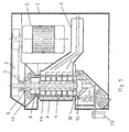
- a vertical grinder 1 has a drive motor 2 for a grinding rotor 4.
- the overdrive is realized by means of several toothed belts 3.
- Around the grinding rotor 4 around a sieve basket 5 is arranged, which is connected to an extraction 6 of the abraded bran particles.
- the grinding rotor 4 has conventional grinding tools and elongated air passage openings in the axial direction.
- the grinding rotor 4 is mounted in a main bearing 7.
- the grinding rotor 4 is designed as a hollow shaft 8 and has an upper air supply 9 and a lower air supply 10.
- the air is supplied via one or two fans, not shown. Due to the uniform supply of air over the entire length of the working space 14, the processed grain is less heated, the processing and removal of the bran is more uniform.
- the grinding rotor 4 is slightly wedge-shaped, the diameter at the top being smaller than at the bottom. The wear is more even.
- a vane rotor with fan effect can be provided, which supports the air flow in the working space 14.
- the product outlet 11 is from above.
- the product outlet is closed by a storage plate 12.
- the storage plate 12 is arranged vertically movable and its movement is controlled by a diaphragm drive 13.
- the diaphragm drive 13 can, as shown, but also be arranged inside the housing of the vertical grinder 1. Likewise, the rotor may also have polishing or peeling tools and / or be arranged horizontally.
- An electronic unit 20 monitors and regulates the diaphragm drive 13 with the aid of control valves 21.
- the current contact pressure force is picked up by a load cell 22 and read into the electronics 20.
- a certain contact pressure can be specified directly on the device (locally) or via a process control system (remotely controlled).
- a pneumatically controlled lever mechanism 23 controls the pre-selected on the electronics 20 product-dependent contact force.
- a small spring 24 absorbs the leverage change caused by the product. At the same time, the slightly bent spring 24 causes a compensation of the transverse forces on the force transducer 22.
Landscapes
- Adjustment And Processing Of Grains (AREA)
- Finish Polishing, Edge Sharpening, And Grinding By Specific Grinding Devices (AREA)
- Mechanical Treatment Of Semiconductor (AREA)
- Disintegrating Or Milling (AREA)
- Combined Means For Separation Of Solids (AREA)
- Apparatuses For Bulk Treatment Of Fruits And Vegetables And Apparatuses For Preparing Feeds (AREA)
- Crushing And Pulverization Processes (AREA)
- Grinding-Machine Dressing And Accessory Apparatuses (AREA)
Description
- Die Erfindung bezieht sich auf eine Schleif- und/oder Poliermaschine für Körnerfrüchte, wie Reis, Weizen oder andere Getreidesorten, mit einem von einem Sieb umgebenen Schleif- und/oder Polierrotor bzw. Schälrotor.
- Herkömmliche Schleif- bzw. Poliermaschinen, insbesondere Schleifmaschinen, besitzen eine Anordnung von Siebsegmenten, die an einem Umfangsende an einer Gelenkachse montiert sind, wogegen das zweite Umfangsende derart um diese Achse schwenkbar ist, dass es mehr oder minder in den von den zu behandelnden Körnerfrüchten erfüllten Raum hineinragt. Dies hat den Zweck, gegen das freie Ende des Siebsegmentes durch Verstellung radial nach innen einen erhöhten Widerstand für die vom Rotor mitgenommenen Körnerfrüchte zu bieten, so dass sich eine Reibung zwischen dem Rotor und den Körnerfrüchten bzw. zwischen den Körnerfrüchten untereinander ergibt.
- Wenn in der vorliegenden Patentanmeldung von "Körnerfrüchten" die Rede ist, so kann es sich um die verschiedensten Körnerfrüchte handeln. Es wird eine solche Behandlung bei Reis oder auch Weizen angewandt, zuweilen aber auch bei anderen Getreidesorten. Überdies ist die Anwendung solcher Maschinen auch schon für Kaffeebohnen vorgeschlagen worden.
- Zur Unterstützung der Siebwirkung und Trennung von Kleieteilchen vom geschliffenen, polierten oder auch vom geschälten Korngut weisen die Rotoren eine Hohlwelle auf, durch deren Öffnungen Druckluft in den Arbeitsraum eingeblasen wird. Hierzu ist die Hohlwelle mit einem Ventilator/Drucklufterzeuger verbunden.
- Um im Arbeitsraum einen konstanten Produktdruck und damit einen konstanten Schäl- oder Poliergrad zu erreichen, ist vor dem Ausgang des Arbeitsraumes eine Stauscheibe angeordnet, die so einstellbar ist, dass dem Produktdruck eine Gegenkraft entgegen gerichtet wird. Die Gegenkraft wird zumeist über ein Hebelwerk/Gestänge, manuell nach Erfahrungswerten eingestellt. Aus
DE-A-3839778 ist es bekannt, die auf ein Verschlussplied wirkende Schließkraft durch eine geregelte Stellvorrichtung einzustellen. - Der Erfindung liegt un die Aufgabe zugrunde, die bekannte Konstruktion unter Vermeidung der geschilderten Nachteile so zu verbessern, dass ein gleichbleibendes Polieren, Schleifen oder Schälen des Korngutes erreicht wird. Die Lösung der Aufgabe erfolgt mit den Merkmalen der Patentansprüche.
- Die Rotorwelle der Schäl-, Schleif- oder Poliermaschine ist in bekannter Weise als Hohlwelle mit Luftdurchtrittsöffnungen auf der Mantelfläche ausgebildet, doch erfolgt der Lufteintritt in die Hohlwelle von beiden Stirnseiten her. Dies ermöglicht eine gleichmässige Belüftung des Arbeitsraumes. Vorteilhaft ist in weiterer Ausbildung die Rotorwelle keilförmig ausgebildet und die Luftdurchtrittsschlitze sind vertikal angeordnet.
- Die Grösse der Anpresskraft hat eine direkte Auswirkung auf den Schäl-, Schleif- oder Poliergrad. Ausserhalb des Arbeitsraumes, vor dem Produktaustrag, befindet sich ein pneumatischer Membranantrieb mit axial angebrachtem Kraftaufnehmer. Mit dieser Anordnung kann eine konstante Anpresskraft am Stauteller erzeugt werden. Bisherige manuelle Einstellungen der Anpresskraft mit Gewichten werden dadurch elektropneumatisch nachgebildet.
- Es ist somit wesentlich einfacher möglich, Schwankungen des Produktdruckes infolge unterschiedlicher Dichte des Produktes auszugleichen (der Stauteller "wandert" entsprechend der Produktdichte).
- Es muss damit nur noch der Anpressdruck gemessen werden, dass ständige Verstellen von Einstellgewichten entfällt. Mittels einer kompakteren, dynamischen Regeleinheit ist es möglich, nicht nur im Betriebszustand den Staudruck (Anpresskraft) feiner zu regeln, sondern das Anfahren der Maschine wesentlich dynamischer zu gestalten. Über Toleranzbänder werden Anpresskraft, Motorenstrom sowie ein geregelter Druck in der Membran überwacht.
- Zur Vergleichmässigung der Arbeitsleistung der Maschine trägt auch die Verwendung von Zahnriemen zum Antrieb der Rotorwelle bei. Bei geringerem Energiebedarf und nahezu ohne Schlupf steigt die Arbeitsleistung.
- Insbesondere durch den Ersatz herkömmlicher elektrischer oder pneumatischer Antriebe durch einen membranbetätigten "Antrieb" des Verschlussorgans Stauteller konnte eine stufenlose Betätigung des Stautellers mit geringen Toleranzen (enges Band) erreicht werden. Besonders vorteilhaft ist, dass die Verschlussstellung auch bei Energieausfall offen gehalten werden kann.
- Der Druck des Produktstroms auf den Stauteller erzeugt eine Kraft, die mit einer Gegenkraft verglichen wird. Diese vom Produkt erzeugte Kraft wird unmittelbar, d. h. direkt von einer kleinen Feder zwischen Hebelmechanik und Kraftaufnehmer aufgenommen und während der Messzeit der Regelung physikalisch gespeichert. Die neu errechnete Kraftanpassung,aufgrund dieser Systemänderung bzw. Ungleichheit der Kräfteverhältnisse wird über elektrische Steuerventile ausgeglichen.
- Die Druckluft im Membranantrieb und somit die Anpresskraft am Stauteller wird dadurch soweit verstellt, bis das Gleichgewicht wieder hergestellt ist. Es wird ausschliesslich auf eine konstante Anpresskraft geregelt, welche unabhängig vom Schüttgewicht ist.
- Weitere Einzelheiten der Erfindung ergeben sich anhand der nachfolgenden Beschreibung vom in der Zeichnung schematisch dargestellten Ausführungsbeispiel. Es zeigen:
- Fig. 1
- einen Längsschnitt durch einen erfindungsgemässen Vertikalschleifer
- Fig. 2
- einen schematischen Querschnitt einer Anordnung zur Regelung des Staudruckes
- Ein Vertikalschleifer 1 weist einen Antriebsmotor 2 für einen Schleifrotor 4 auf. Der Übertrieb ist mittels mehrerer Zahnriemen 3 realisiert. Um den Schleifrotor 4 herum ist ein Siebkorb 5 angeordnet, der mit einer Absaugung 6 der abgeschliffenen Kleieteilchen verbunden ist. Der Schleifrotor 4 weist übliche Schleifwerkzeuge und längliche Luftdurchtrittsöffnungen in Achsrichtung auf. Der Schleifrotor 4 ist in einem Hauptlager 7 gelagert.
- Der Schleifrotor 4 ist als Hohlwelle 8 ausgebildet und weist eine obere Luftzufuhr 9 und eine untere Luftzuführung 10 auf. Die Luftzufuhr erfolgt über einen bzw. zwei, nicht dargestellte Ventilatoren. Infolge der gleichmässigen Zufuhr der Luft über die gesamte Länge des Arbeitsraumes 14 wird das bearbeitete Korngut weniger erwärmt, die Bearbeitung und Entfernung der Kleie erfolgt gleichmässiger.
- Der Schleifrotor 4 ist leicht keilförmig ausgebildet, wobei der Durchmesser oben kleiner als unten ist. Der Verschleiss ist gleichmässiger.
- Zusätzlich kann noch ein Flügelrotor mit Lüfterwirkung vorgesehen sein, der die Luftströmung im Arbeitsraum 14 unterstützt.
- Der Produktauslass 11 erfolgt von oben. Der Produktauslass ist durch einen Stauteller 12 verschlossen. Der Stauteller 12 ist vertikal beweglich angeordnet und dessen Bewegung wird über einen Membranantrieb 13 geregelt.
- Der Membranantrieb 13 kann wie dargestellt aber auch innen im Gehäuse des Vertikalschleifers 1 angeordnet sein. Ebenso kann der Rotor auch Polier- oder Schälwerkzeuge aufweisen und/oder horizontal angeordnet sein.
- Eine Elektronik 20 überwacht und reguliert mit Hilfe von Steuerventilen 21 den Membranantrieb 13. Die aktuelle Anpresskraft wird von einem Kraftaufnehmer 22 aufgenommen und in die Elektronik 20 eingelesen. Eine bestimmte Anpresskraft kann direkt am Gerät (lokal) oder über ein Prozessleitsystem (ferngesteuert) vorgegeben werden.
- Eine pneumatisch gesteuerte Hebelmechanik 23 regelt die an der Elektronik 20 vorgewählte produktabhängige Anpresskraft. Eine kleine Feder 24 nimmt die durch das Produkt hervorgerufene Hebelkraftveränderung auf. Gleichzeitig bewirkt die leicht gebogene Feder 24 eine Kompensation der Querkräfte am Kraftaufnehmer 22.
- Übersteigt der Mötorenstrom eine in der Elektronik 20 festgelegte Stromgrenze, so wird die Hebelmechanik 23 automatisch entlastet.
-
- 1
- Vertikalschleifer
- 2
- Antriebsmotor
- 3
- Zahnriemen
- 4
- Schleifrotor
- 5
- Siebkorb
- 6
- Absaugung
- 7
- Hauptlager
- 8
- Hohlwelle
- 9
- Luftzufuhr
- 10
- Luftzufuhr
- 11
- Produktauslass
- 12
- Stauteller
- 13
- Membranantrieb
- 14
- Arbeitsraum
- 20
- Elektronik
- 21
- Steuerventil
- 22
- Kraftaufnehmer
- 23
- Hebelmechanik
- 24
- Feder
Claims (3)
- Schleif-, Polier- oder Schälmaschine mit horizontal oder vertikal angeordnetem Arbeitsraum, der zwischen einem mit Werkzeugen bestückten Rotor und einem Siebkorb (5) gebildet ist, dessen Produktauslass mit einem Stauteller (12) verschliessbar ist und wobei der Rotor als Hohlwelle (8) mit Luftdurchtrittsöffnungen ausgebildet ist, dadurch gekennzeichnet, dass die Hohlwelle (8) eine obere und eine untere Luftzuführung (9, 10) aufweist und dass der Stauteller (12) beweglich ist und mittels eines Membranantriebes (13) stufenlos betätigbar ist.
- Schleif-, Polier- oder Schälmaschine nach Anspruch 1, dadurch gekennzeichnet, dass die Luftdurchtrittsöffnungen länglich, in Achsrichtung verlaufend angeordnet sind.
- Schleif-, Polier- oder Schälmaschine nach Anspruch 1 oder 2, dadurch gekennzeichnet, dass der Rotor keilförmig ausgebildet ist.
Applications Claiming Priority (2)
| Application Number | Priority Date | Filing Date | Title |
|---|---|---|---|
| DE10341223A DE10341223A1 (de) | 2003-09-04 | 2003-09-04 | Schleif- bzw. Poliermaschine |
| PCT/CH2004/000445 WO2005023428A1 (de) | 2003-09-04 | 2004-07-13 | Schleif- bzw. poliermaschine |
Publications (2)
| Publication Number | Publication Date |
|---|---|
| EP1670590A1 EP1670590A1 (de) | 2006-06-21 |
| EP1670590B1 true EP1670590B1 (de) | 2009-08-26 |
Family
ID=34202394
Family Applications (1)
| Application Number | Title | Priority Date | Filing Date |
|---|---|---|---|
| EP04738085A Expired - Lifetime EP1670590B1 (de) | 2003-09-04 | 2004-07-13 | Schleif- bzw. poliermaschine |
Country Status (11)
| Country | Link |
|---|---|
| US (1) | US20060286905A1 (de) |
| EP (1) | EP1670590B1 (de) |
| JP (1) | JP4921970B2 (de) |
| CN (1) | CN1845792A (de) |
| AT (1) | ATE440665T1 (de) |
| BR (1) | BRPI0413810A (de) |
| CO (1) | CO5670329A2 (de) |
| DE (2) | DE10341223A1 (de) |
| ES (1) | ES2332365T3 (de) |
| MX (1) | MXPA06002395A (de) |
| WO (1) | WO2005023428A1 (de) |
Families Citing this family (6)
| Publication number | Priority date | Publication date | Assignee | Title |
|---|---|---|---|---|
| DE102005027343A1 (de) * | 2005-06-13 | 2006-12-14 | Bühler AG | Schleifmaschine |
| CN102553691A (zh) * | 2011-12-09 | 2012-07-11 | 中国科学院南京土壤研究所 | 高含水有机物粉碎机 |
| WO2017093513A1 (de) * | 2015-12-04 | 2017-06-08 | Bühler AG | Rotor, schleifmaschine, luftabsaugummantelung und schleifelement für eine schleifmaschine |
| CN106238332B (zh) * | 2016-08-26 | 2020-05-26 | 新昌县科宇机械有限公司 | 一种刨花分选装置 |
| CN106345558B (zh) * | 2016-11-16 | 2018-07-31 | 余庆县大凉山米业有限责任公司 | 大米抛光装置 |
| CN113680419B (zh) * | 2021-09-14 | 2025-01-07 | 曹县鲁曹高新机械制造有限公司 | 一种燕麦整粒取仁装置 |
Family Cites Families (16)
| Publication number | Priority date | Publication date | Assignee | Title |
|---|---|---|---|---|
| JPS5234257A (en) * | 1975-09-10 | 1977-03-16 | Iony Kk | Grain pearling device |
| JPS59105852A (ja) * | 1982-12-10 | 1984-06-19 | 株式会社 サタケ | 精穀機の抵抗蓋調節装置 |
| SU1165308A1 (ru) * | 1984-01-19 | 1985-07-07 | Всесоюзное Научно-Производственное Объединение По Механизации Орошения "Радуга" | Генератор командных импульсов |
| JPH0264238A (ja) * | 1988-08-29 | 1990-03-05 | Honda Motor Co Ltd | 内燃機関のスロットル制御装置 |
| DE3839778A1 (de) * | 1988-11-25 | 1990-05-31 | Buehler Gmbh | Schleif- oder poliermaschine fuer koerner, wie reis, mais, weizen od. dgl. |
| JPH03292404A (ja) * | 1990-04-11 | 1991-12-24 | Kousou Service Kk | ダイヤフラム式駆動装置 |
| JPH06102159B2 (ja) * | 1991-02-15 | 1994-12-14 | 計彦 増井 | 縦型精米機の精白室流入量自動制御装置 |
| JP3106444B2 (ja) * | 1992-06-16 | 2000-11-06 | 株式会社佐竹製作所 | 竪型精穀機 |
| JP3201496B2 (ja) * | 1993-03-23 | 2001-08-20 | 株式会社サタケ | 研削式竪型精米機 |
| JP3266167B2 (ja) * | 1993-08-06 | 2002-03-18 | 株式会社サタケ | 竪型研削式精穀機の抵抗体調節装置 |
| JPH07227550A (ja) * | 1994-02-17 | 1995-08-29 | Satake Eng Co Ltd | 研削式竪型精穀機 |
| DE4420863C2 (de) * | 1994-06-15 | 1998-05-14 | Ott Kg Lewa | Gesteuerte Schnüffelbehinderung für Hochdruck-Membranpumpen |
| AU660879B1 (en) * | 1994-08-22 | 1995-07-06 | Satake Corporation | Vertical milling machine |
| JP3472646B2 (ja) * | 1995-06-12 | 2003-12-02 | 株式会社フジキン | 流体切換装置 |
| JP3435914B2 (ja) * | 1995-07-03 | 2003-08-11 | 株式会社サタケ | 精穀機の抵抗板調節装置 |
| JP3514606B2 (ja) * | 1997-06-03 | 2004-03-31 | 三菱電機株式会社 | ターボチャージャの制御装置 |
-
2003
- 2003-09-04 DE DE10341223A patent/DE10341223A1/de not_active Withdrawn
-
2004
- 2004-07-13 AT AT04738085T patent/ATE440665T1/de active
- 2004-07-13 CN CNA2004800252863A patent/CN1845792A/zh active Pending
- 2004-07-13 MX MXPA06002395A patent/MXPA06002395A/es not_active Application Discontinuation
- 2004-07-13 US US10/567,785 patent/US20060286905A1/en not_active Abandoned
- 2004-07-13 BR BRPI0413810-4A patent/BRPI0413810A/pt not_active IP Right Cessation
- 2004-07-13 DE DE502004009979T patent/DE502004009979D1/de not_active Expired - Lifetime
- 2004-07-13 ES ES04738085T patent/ES2332365T3/es not_active Expired - Lifetime
- 2004-07-13 WO PCT/CH2004/000445 patent/WO2005023428A1/de not_active Ceased
- 2004-07-13 EP EP04738085A patent/EP1670590B1/de not_active Expired - Lifetime
- 2004-07-13 JP JP2006525019A patent/JP4921970B2/ja not_active Expired - Fee Related
-
2006
- 2006-02-27 CO CO06019213A patent/CO5670329A2/es not_active Application Discontinuation
Also Published As
| Publication number | Publication date |
|---|---|
| DE10341223A1 (de) | 2005-03-24 |
| WO2005023428A1 (de) | 2005-03-17 |
| EP1670590A1 (de) | 2006-06-21 |
| ATE440665T1 (de) | 2009-09-15 |
| MXPA06002395A (es) | 2006-06-20 |
| JP2007508920A (ja) | 2007-04-12 |
| DE502004009979D1 (de) | 2009-10-08 |
| US20060286905A1 (en) | 2006-12-21 |
| JP4921970B2 (ja) | 2012-04-25 |
| CO5670329A2 (es) | 2006-08-31 |
| BRPI0413810A (pt) | 2006-10-17 |
| ES2332365T3 (es) | 2010-02-03 |
| CN1845792A (zh) | 2006-10-11 |
Similar Documents
| Publication | Publication Date | Title |
|---|---|---|
| DE3427284C2 (de) | Sieb- und Rotor-Baugruppe für Körner-Enthüls-, Schäl-, Schleif- und Poliermaschinen | |
| DE2947758C2 (de) | ||
| DE69417666T2 (de) | Abrasive Getreide-Bleichmaschine mit einem perforierten zylindrischen Körper zur Entfernung von Kleie | |
| WO1989003245A1 (fr) | Procede de fabrication de produits de ble moulu et moulin a cylindres | |
| EP1670590B1 (de) | Schleif- bzw. poliermaschine | |
| EP2726208A2 (de) | Verfahren und vorrichtung für die herstellung von mehl und/oder griess | |
| EP3261765B1 (de) | Walzenstuhl, aspirationsbaugruppe und verfahren zum nachrüsten eines walzenstuhles | |
| EP2651563B1 (de) | Walzenmühle und verfahren zum betreiben einer walzenmühle | |
| DE9017817U1 (de) | Schrotmühle, insbesondere Naßschrotmühle für die Maischeherstellung bei der Biererzeugung | |
| EP1413532B1 (de) | Speiseeinrichtung | |
| DE102019127893A1 (de) | Vorrichtung zum Zerkleinern von schüttfähigem Aufgabegut | |
| EP3900833B1 (de) | Vorrichtung zur entspelzung von spelzgetreide | |
| DE102018130862A1 (de) | Pressschneckenseparator | |
| EP1704974B1 (de) | Spannen und Befestigen der Messerwerkzeuge einer Lochrotorentrindungsmaschine | |
| EP1778403A1 (de) | Verfahren zur regelung der walzenanpressung bei walzenschälern | |
| DE10312605B4 (de) | Einrichtung zum Trennen und Abfördern von Rohstoffen | |
| DE102004033123B3 (de) | Zellenradschleuse mit hundertprozentiger spaltfreier Abdichtung zwischen Zellenradwand und Zellenradrotor einschließlich der Stirnseiten des Rotors, sowie absolut gleichmäßiger Steuerung der Andrückkraft der Verschleißteile über die gesamte Lebensdauer der Zellenradschleuse, welche mit einer automatischen, absolut genauen Verschleißanzeige, versehen ist | |
| EP3456665B1 (de) | Zellenradschleuse | |
| EP3714098A1 (de) | Mahlvorrichtung | |
| WO2006092069A1 (de) | Walzenschäler | |
| DE3823700A1 (de) | Druck- und foerderschnecke fuer fleischwoelfe | |
| CN104707682A (zh) | 出米流量调节装置和碾米机 | |
| DE202022104529U1 (de) | Separator zum Separieren eines Mediums | |
| DE38781C (de) | Neuerung an Kleedreschmaschinen | |
| DE1607575C3 (de) | Verfahren zum Regeln einer Sichter mahlanlage |
Legal Events
| Date | Code | Title | Description |
|---|---|---|---|
| PUAI | Public reference made under article 153(3) epc to a published international application that has entered the european phase |
Free format text: ORIGINAL CODE: 0009012 |
|
| 17P | Request for examination filed |
Effective date: 20060110 |
|
| AK | Designated contracting states |
Kind code of ref document: A1 Designated state(s): AT BE BG CH CY CZ DE DK EE ES FI FR GB GR HU IE IT LI LU MC NL PL PT RO SE SI SK TR |
|
| RIN1 | Information on inventor provided before grant (corrected) |
Inventor name: KAUFMANN, CHRISTOPH Inventor name: GOERLITZ, FRANK-OTTO Inventor name: BROCKFELD, MARKUS |
|
| DAX | Request for extension of the european patent (deleted) | ||
| 17Q | First examination report despatched |
Effective date: 20071221 |
|
| GRAP | Despatch of communication of intention to grant a patent |
Free format text: ORIGINAL CODE: EPIDOSNIGR1 |
|
| GRAS | Grant fee paid |
Free format text: ORIGINAL CODE: EPIDOSNIGR3 |
|
| GRAA | (expected) grant |
Free format text: ORIGINAL CODE: 0009210 |
|
| AK | Designated contracting states |
Kind code of ref document: B1 Designated state(s): AT BE BG CH CY CZ DE DK EE ES FI FR GB GR HU IE IT LI LU MC NL PL PT RO SE SI SK TR |
|
| REG | Reference to a national code |
Ref country code: GB Ref legal event code: FG4D Free format text: NOT ENGLISH |
|
| REG | Reference to a national code |
Ref country code: CH Ref legal event code: EP |
|
| REG | Reference to a national code |
Ref country code: IE Ref legal event code: FG4D Free format text: LANGUAGE OF EP DOCUMENT: GERMAN |
|
| REF | Corresponds to: |
Ref document number: 502004009979 Country of ref document: DE Date of ref document: 20091008 Kind code of ref document: P |
|
| REG | Reference to a national code |
Ref country code: CH Ref legal event code: NV Representative=s name: HEPP WENGER RYFFEL AG |
|
| PG25 | Lapsed in a contracting state [announced via postgrant information from national office to epo] |
Ref country code: SE Free format text: LAPSE BECAUSE OF FAILURE TO SUBMIT A TRANSLATION OF THE DESCRIPTION OR TO PAY THE FEE WITHIN THE PRESCRIBED TIME-LIMIT Effective date: 20090826 Ref country code: FI Free format text: LAPSE BECAUSE OF FAILURE TO SUBMIT A TRANSLATION OF THE DESCRIPTION OR TO PAY THE FEE WITHIN THE PRESCRIBED TIME-LIMIT Effective date: 20090826 |
|
| NLV1 | Nl: lapsed or annulled due to failure to fulfill the requirements of art. 29p and 29m of the patents act | ||
| REG | Reference to a national code |
Ref country code: ES Ref legal event code: FG2A Ref document number: 2332365 Country of ref document: ES Kind code of ref document: T3 |
|
| PG25 | Lapsed in a contracting state [announced via postgrant information from national office to epo] |
Ref country code: PL Free format text: LAPSE BECAUSE OF FAILURE TO SUBMIT A TRANSLATION OF THE DESCRIPTION OR TO PAY THE FEE WITHIN THE PRESCRIBED TIME-LIMIT Effective date: 20090826 Ref country code: SI Free format text: LAPSE BECAUSE OF FAILURE TO SUBMIT A TRANSLATION OF THE DESCRIPTION OR TO PAY THE FEE WITHIN THE PRESCRIBED TIME-LIMIT Effective date: 20090826 Ref country code: NL Free format text: LAPSE BECAUSE OF FAILURE TO SUBMIT A TRANSLATION OF THE DESCRIPTION OR TO PAY THE FEE WITHIN THE PRESCRIBED TIME-LIMIT Effective date: 20090826 |
|
| PG25 | Lapsed in a contracting state [announced via postgrant information from national office to epo] |
Ref country code: CY Free format text: LAPSE BECAUSE OF FAILURE TO SUBMIT A TRANSLATION OF THE DESCRIPTION OR TO PAY THE FEE WITHIN THE PRESCRIBED TIME-LIMIT Effective date: 20090826 Ref country code: BG Free format text: LAPSE BECAUSE OF FAILURE TO SUBMIT A TRANSLATION OF THE DESCRIPTION OR TO PAY THE FEE WITHIN THE PRESCRIBED TIME-LIMIT Effective date: 20091126 Ref country code: PT Free format text: LAPSE BECAUSE OF FAILURE TO SUBMIT A TRANSLATION OF THE DESCRIPTION OR TO PAY THE FEE WITHIN THE PRESCRIBED TIME-LIMIT Effective date: 20091228 |
|
| REG | Reference to a national code |
Ref country code: IE Ref legal event code: FD4D |
|
| PG25 | Lapsed in a contracting state [announced via postgrant information from national office to epo] |
Ref country code: CZ Free format text: LAPSE BECAUSE OF FAILURE TO SUBMIT A TRANSLATION OF THE DESCRIPTION OR TO PAY THE FEE WITHIN THE PRESCRIBED TIME-LIMIT Effective date: 20090826 Ref country code: DK Free format text: LAPSE BECAUSE OF FAILURE TO SUBMIT A TRANSLATION OF THE DESCRIPTION OR TO PAY THE FEE WITHIN THE PRESCRIBED TIME-LIMIT Effective date: 20090826 Ref country code: RO Free format text: LAPSE BECAUSE OF FAILURE TO SUBMIT A TRANSLATION OF THE DESCRIPTION OR TO PAY THE FEE WITHIN THE PRESCRIBED TIME-LIMIT Effective date: 20090826 Ref country code: EE Free format text: LAPSE BECAUSE OF FAILURE TO SUBMIT A TRANSLATION OF THE DESCRIPTION OR TO PAY THE FEE WITHIN THE PRESCRIBED TIME-LIMIT Effective date: 20090826 Ref country code: IE Free format text: LAPSE BECAUSE OF FAILURE TO SUBMIT A TRANSLATION OF THE DESCRIPTION OR TO PAY THE FEE WITHIN THE PRESCRIBED TIME-LIMIT Effective date: 20090826 |
|
| PG25 | Lapsed in a contracting state [announced via postgrant information from national office to epo] |
Ref country code: SK Free format text: LAPSE BECAUSE OF FAILURE TO SUBMIT A TRANSLATION OF THE DESCRIPTION OR TO PAY THE FEE WITHIN THE PRESCRIBED TIME-LIMIT Effective date: 20090826 |
|
| PLBE | No opposition filed within time limit |
Free format text: ORIGINAL CODE: 0009261 |
|
| STAA | Information on the status of an ep patent application or granted ep patent |
Free format text: STATUS: NO OPPOSITION FILED WITHIN TIME LIMIT |
|
| 26N | No opposition filed |
Effective date: 20100527 |
|
| PG25 | Lapsed in a contracting state [announced via postgrant information from national office to epo] |
Ref country code: GR Free format text: LAPSE BECAUSE OF FAILURE TO SUBMIT A TRANSLATION OF THE DESCRIPTION OR TO PAY THE FEE WITHIN THE PRESCRIBED TIME-LIMIT Effective date: 20091127 |
|
| BERE | Be: lapsed |
Owner name: BUHLER A.G. Effective date: 20100731 |
|
| PG25 | Lapsed in a contracting state [announced via postgrant information from national office to epo] |
Ref country code: MC Free format text: LAPSE BECAUSE OF NON-PAYMENT OF DUE FEES Effective date: 20100731 |
|
| PG25 | Lapsed in a contracting state [announced via postgrant information from national office to epo] |
Ref country code: BE Free format text: LAPSE BECAUSE OF NON-PAYMENT OF DUE FEES Effective date: 20100731 |
|
| PG25 | Lapsed in a contracting state [announced via postgrant information from national office to epo] |
Ref country code: HU Free format text: LAPSE BECAUSE OF FAILURE TO SUBMIT A TRANSLATION OF THE DESCRIPTION OR TO PAY THE FEE WITHIN THE PRESCRIBED TIME-LIMIT Effective date: 20100227 Ref country code: LU Free format text: LAPSE BECAUSE OF NON-PAYMENT OF DUE FEES Effective date: 20100713 |
|
| PG25 | Lapsed in a contracting state [announced via postgrant information from national office to epo] |
Ref country code: TR Free format text: LAPSE BECAUSE OF FAILURE TO SUBMIT A TRANSLATION OF THE DESCRIPTION OR TO PAY THE FEE WITHIN THE PRESCRIBED TIME-LIMIT Effective date: 20090826 |
|
| REG | Reference to a national code |
Ref country code: FR Ref legal event code: PLFP Year of fee payment: 13 |
|
| REG | Reference to a national code |
Ref country code: FR Ref legal event code: PLFP Year of fee payment: 14 |
|
| PGFP | Annual fee paid to national office [announced via postgrant information from national office to epo] |
Ref country code: FR Payment date: 20170720 Year of fee payment: 14 Ref country code: IT Payment date: 20170721 Year of fee payment: 14 Ref country code: CH Payment date: 20170724 Year of fee payment: 14 Ref country code: GB Payment date: 20170724 Year of fee payment: 14 Ref country code: DE Payment date: 20170724 Year of fee payment: 14 Ref country code: ES Payment date: 20170818 Year of fee payment: 14 |
|
| PGFP | Annual fee paid to national office [announced via postgrant information from national office to epo] |
Ref country code: AT Payment date: 20170719 Year of fee payment: 14 |
|
| REG | Reference to a national code |
Ref country code: DE Ref legal event code: R119 Ref document number: 502004009979 Country of ref document: DE |
|
| REG | Reference to a national code |
Ref country code: CH Ref legal event code: PL |
|
| REG | Reference to a national code |
Ref country code: AT Ref legal event code: MM01 Ref document number: 440665 Country of ref document: AT Kind code of ref document: T Effective date: 20180713 |
|
| GBPC | Gb: european patent ceased through non-payment of renewal fee |
Effective date: 20180713 |
|
| PG25 | Lapsed in a contracting state [announced via postgrant information from national office to epo] |
Ref country code: AT Free format text: LAPSE BECAUSE OF NON-PAYMENT OF DUE FEES Effective date: 20180713 Ref country code: LI Free format text: LAPSE BECAUSE OF NON-PAYMENT OF DUE FEES Effective date: 20180731 Ref country code: DE Free format text: LAPSE BECAUSE OF NON-PAYMENT OF DUE FEES Effective date: 20190201 Ref country code: FR Free format text: LAPSE BECAUSE OF NON-PAYMENT OF DUE FEES Effective date: 20180731 Ref country code: GB Free format text: LAPSE BECAUSE OF NON-PAYMENT OF DUE FEES Effective date: 20180713 Ref country code: CH Free format text: LAPSE BECAUSE OF NON-PAYMENT OF DUE FEES Effective date: 20180731 |
|
| PG25 | Lapsed in a contracting state [announced via postgrant information from national office to epo] |
Ref country code: IT Free format text: LAPSE BECAUSE OF NON-PAYMENT OF DUE FEES Effective date: 20180713 |
|
| REG | Reference to a national code |
Ref country code: ES Ref legal event code: FD2A Effective date: 20190917 |
|
| PG25 | Lapsed in a contracting state [announced via postgrant information from national office to epo] |
Ref country code: ES Free format text: LAPSE BECAUSE OF NON-PAYMENT OF DUE FEES Effective date: 20180714 |