EP1670666B1 - Bras d'essuie-glace, en particulier pour dispositif essuie-glace d'un vehicule automobile - Google Patents
Bras d'essuie-glace, en particulier pour dispositif essuie-glace d'un vehicule automobile Download PDFInfo
- Publication number
- EP1670666B1 EP1670666B1 EP04725603A EP04725603A EP1670666B1 EP 1670666 B1 EP1670666 B1 EP 1670666B1 EP 04725603 A EP04725603 A EP 04725603A EP 04725603 A EP04725603 A EP 04725603A EP 1670666 B1 EP1670666 B1 EP 1670666B1
- Authority
- EP
- European Patent Office
- Prior art keywords
- wiper
- wiper arm
- struts
- fastening part
- wiper blade
- Prior art date
- Legal status (The legal status is an assumption and is not a legal conclusion. Google has not performed a legal analysis and makes no representation as to the accuracy of the status listed.)
- Expired - Lifetime
Links
- 239000002184 metal Substances 0.000 description 7
- 229910000831 Steel Inorganic materials 0.000 description 3
- 239000010959 steel Substances 0.000 description 3
- 229910001369 Brass Inorganic materials 0.000 description 2
- 230000008901 benefit Effects 0.000 description 2
- 239000010951 brass Substances 0.000 description 2
- 230000008859 change Effects 0.000 description 2
- 230000007246 mechanism Effects 0.000 description 2
- 230000001419 dependent effect Effects 0.000 description 1
- 238000004512 die casting Methods 0.000 description 1
- 239000000463 material Substances 0.000 description 1
- 238000005058 metal casting Methods 0.000 description 1
- 238000000034 method Methods 0.000 description 1
- 230000008569 process Effects 0.000 description 1
- 239000000725 suspension Substances 0.000 description 1
Images


Classifications
-
- B—PERFORMING OPERATIONS; TRANSPORTING
- B60—VEHICLES IN GENERAL
- B60S—SERVICING, CLEANING, REPAIRING, SUPPORTING, LIFTING, OR MANOEUVRING OF VEHICLES, NOT OTHERWISE PROVIDED FOR
- B60S1/00—Cleaning of vehicles
- B60S1/02—Cleaning windscreens, windows or optical devices
- B60S1/04—Wipers or the like, e.g. scrapers
- B60S1/32—Wipers or the like, e.g. scrapers characterised by constructional features of wiper blade arms or blades
- B60S1/38—Wiper blades
- B60S1/3848—Flat-type wiper blade, i.e. without harness
- B60S1/3872—Flat-type wiper blade, i.e. without harness without connector, e.g. connection to wiper arm via squeegee or vertebra
-
- B—PERFORMING OPERATIONS; TRANSPORTING
- B60—VEHICLES IN GENERAL
- B60S—SERVICING, CLEANING, REPAIRING, SUPPORTING, LIFTING, OR MANOEUVRING OF VEHICLES, NOT OTHERWISE PROVIDED FOR
- B60S1/00—Cleaning of vehicles
- B60S1/02—Cleaning windscreens, windows or optical devices
- B60S1/04—Wipers or the like, e.g. scrapers
- B60S1/32—Wipers or the like, e.g. scrapers characterised by constructional features of wiper blade arms or blades
-
- B—PERFORMING OPERATIONS; TRANSPORTING
- B60—VEHICLES IN GENERAL
- B60S—SERVICING, CLEANING, REPAIRING, SUPPORTING, LIFTING, OR MANOEUVRING OF VEHICLES, NOT OTHERWISE PROVIDED FOR
- B60S1/00—Cleaning of vehicles
- B60S1/02—Cleaning windscreens, windows or optical devices
- B60S1/04—Wipers or the like, e.g. scrapers
- B60S1/32—Wipers or the like, e.g. scrapers characterised by constructional features of wiper blade arms or blades
- B60S1/34—Wiper arms; Mountings therefor
-
- B—PERFORMING OPERATIONS; TRANSPORTING
- B60—VEHICLES IN GENERAL
- B60S—SERVICING, CLEANING, REPAIRING, SUPPORTING, LIFTING, OR MANOEUVRING OF VEHICLES, NOT OTHERWISE PROVIDED FOR
- B60S1/00—Cleaning of vehicles
- B60S1/02—Cleaning windscreens, windows or optical devices
- B60S1/04—Wipers or the like, e.g. scrapers
- B60S1/32—Wipers or the like, e.g. scrapers characterised by constructional features of wiper blade arms or blades
- B60S1/34—Wiper arms; Mountings therefor
- B60S1/3425—Constructional aspects of the arm
- B60S1/3427—Arm piece, link piece and mounting head formed as one element
-
- B—PERFORMING OPERATIONS; TRANSPORTING
- B60—VEHICLES IN GENERAL
- B60S—SERVICING, CLEANING, REPAIRING, SUPPORTING, LIFTING, OR MANOEUVRING OF VEHICLES, NOT OTHERWISE PROVIDED FOR
- B60S1/00—Cleaning of vehicles
- B60S1/02—Cleaning windscreens, windows or optical devices
- B60S1/04—Wipers or the like, e.g. scrapers
- B60S1/32—Wipers or the like, e.g. scrapers characterised by constructional features of wiper blade arms or blades
- B60S1/34—Wiper arms; Mountings therefor
- B60S1/3425—Constructional aspects of the arm
- B60S1/3436—Mounting heads
-
- B—PERFORMING OPERATIONS; TRANSPORTING
- B60—VEHICLES IN GENERAL
- B60S—SERVICING, CLEANING, REPAIRING, SUPPORTING, LIFTING, OR MANOEUVRING OF VEHICLES, NOT OTHERWISE PROVIDED FOR
- B60S1/00—Cleaning of vehicles
- B60S1/02—Cleaning windscreens, windows or optical devices
- B60S1/04—Wipers or the like, e.g. scrapers
- B60S1/32—Wipers or the like, e.g. scrapers characterised by constructional features of wiper blade arms or blades
- B60S1/38—Wiper blades
-
- B—PERFORMING OPERATIONS; TRANSPORTING
- B60—VEHICLES IN GENERAL
- B60S—SERVICING, CLEANING, REPAIRING, SUPPORTING, LIFTING, OR MANOEUVRING OF VEHICLES, NOT OTHERWISE PROVIDED FOR
- B60S1/00—Cleaning of vehicles
- B60S1/02—Cleaning windscreens, windows or optical devices
- B60S1/04—Wipers or the like, e.g. scrapers
- B60S1/32—Wipers or the like, e.g. scrapers characterised by constructional features of wiper blade arms or blades
- B60S1/34—Wiper arms; Mountings therefor
- B60S1/3425—Constructional aspects of the arm
- B60S1/3445—Joints between elements
- B60S1/345—Joints between elements the elements being a link piece and a mounting head
Definitions
- the invention relates to a wiper arm, in particular for a windscreen wiper device of a motor vehicle according to the preamble of the independent claim.
- wiper arms for windscreen wiper devices of motor vehicles essentially comprise a fastening part, which serves for fastening the wiper arm to a wiper shaft of the windshield wiper device, as well as a joint part, to which a wiper blade can be articulated.
- the wiper arm is able to slide over the window of the motor vehicle in a plane of movement which is perpendicular to the axis of rotation of the wiper shaft.
- the hinge part is formed substantially from a U-shaped bent sheet metal profile, wherein the base of the U-shaped profile are arranged substantially parallel to the plane of movement of the wiper blade and the legs of the U-shaped profile perpendicular to the plane of movement of the wiper blade.
- the hinge part and the fastening part are hinged together and additionally linked by a spring.
- the spring In the working position, when the wiper blade hinged to the free end of the joint part rests on the window of the motor vehicle, the spring is under pretension so that a bearing force is generated which presses the wiper blade onto the window.
- Such wiper arms require many parts, such as springs, hinge pins, suspension bolts, etc., which causes high costs. Furthermore cause such wiper arms by their box-shaped, inverted U-shaped profile a very high air resistance and their robust appearance does not contribute to the pleasing of the motor vehicle.
- the wiper arm according to the invention with the features of the main claim has the advantage that the hinge part is essentially formed by two struts, each having two ends, wherein each one end to the fastening part and the other end is connectable to the wiper blade. In this way, results in a cost wiper arm, which also has only a low air resistance and is very pleasing in appearance. Furthermore, the length of the struts 20 is chosen so that one strut is slightly longer than the other, so that they open into the fastening part 12 along the longitudinal extent of the wiper arm 10 and the fastening part 12 in different places.
- the hinge part can be bent particularly cost-effectively from a single metal or plastic rod.
- the joint part is movable in a flap plane substantially perpendicular to the plane of movement, since in this way a slight change of the wiper blade is possible.
- the hinge part can be folded by overcoming a spring-like force between at least two rest positions. Thereby, the wiper arm can be lifted off the disc and remains, lifted off the disc, in a rest position, so that an even easier change of the wiper blade is ensured.
- the one ends of the struts are bent inwards approximately parallel to the base and engage in openings in the fastening part in the manner of a clip.
- the wiper blade in the relaxed state perpendicular to the plane of movement has a bend.
- FIG. 1 shows a wiper arm 10 according to the invention in a plan view.
- This essentially comprises a fastening part 12 and a hinge part 14.
- the fastening part 12 is of substantially elongated shape and has at one end a hole 16 for attachment to a wiper shaft. In the middle region of its longitudinal extension, it has a taper of the cross section.
- the hole 16 is formed multi-step in the axial direction and includes a conical step, so that a secure hold of the fastening part 12 is ensured on the wiper shaft of the windscreen wiper device.
- the hinge part 14 is articulated.
- the hinge part 14 is formed in its longitudinal extent by a bracket 18 which is of substantially U-shaped configuration.
- the two legs of the U-shaped bracket 18 form struts 20, which are connected by the base 22 of the U-shaped bracket 18 at the, the fastening part 12 opposite end of the hinge part 14.
- a diaphragm 24 is still arranged in the region of the articulation between the fastening part 12 and joint part 14, which is formed of sheet metal or plastic and clipped onto the fastening part 12 or the hinge part 14, glued or stamped.
- the aperture 24 may be attached in a different manner to the fastening part 12 or to the struts 20 of the joint part 14.
- the wiper arm oscillates around the hole 16 in which the wiper shaft is mounted. This oscillating movement defines the plane of movement in which the wiper arm or the wiper blade 30 hinged to the base 22 of the wiper arm moves.
- FIG. 2 is the wiper arm off FIG. 1 shown in a partial sectional view.
- the fastening part 12 is cut open in the region of the articulation of the struts 20, the fastening part 12 has on its sides two openings 26 which through metal bushings 28 (FIGS. FIG. 3 ) are reinforced.
- the struts 20 of the joint part 14, and the bracket 18 are bent at its one, the fastening part end facing approximately parallel to the base inwardly, so that they engage in the openings 26 and in the metal bushings 28 of the fastening part 12 like a clip.
- the struts 20 of the bracket 18 therefore open into the fastening part.
- the panel 24 clamps the ends of the struts 20 such that they can not escape from the holes 26. Furthermore, a Abklappbegrenzung is achieved by the aperture 24, which limits the Abklappwinkel of the bracket 18 relative to the fastening part 12.
- the struts 20, the FIG. 2b shown here only as lines, are here projected into a plane and open along the longitudinal extent of the fastening part 12 in two different positions in the fastening part 12.
- the two partial circular paths B1 and B2 correspond to the respective radii that the respective strut 20 tries to describe.
- the relaxed rest positions RP1, RP2 of the joint part 14 are as in FIG FIG. 2 visible, exactly those in which the two radii of the two struts 20 overlap. In the remaining areas, one of the struts 20 is always elastically compressed or stretched, resulting in a spring-like force in the direction of one or the other rest position RP1, RP2.
- FIG. 3 is the fastener off Figures 1 and 2 shown again in a partial section.
- the attachment member 12 is of substantially elongate shape and connectable at one end to the wiper shaft of the windshield wiper device through the hole 16.
- the other, free end of the fastening part 12 has two openings 26 which are arranged opposite and are designed as bores.
- the two openings 26 are lined with metal bushings 28, which are made of steel or brass and a slight sliding of the ends of the struts 20 (FIG. FIG. 2 ) enable.
- the two openings 26 are arranged offset.
- the openings 26 extend substantially perpendicular to the hole 16 and thus substantially perpendicular to the wiper shaft.
- the openings 26 are axially parallel to the plane of movement of the wiper arm 10th
- FIG. 4 a side view of the fastening part 12 is shown in a partial sectional view.
- the two openings 26 are arranged opposite one another and offset along the longitudinal extent, the central axes of the openings 26 extend perpendicular to the hole 16 of the fastening part 12.
- the hole 16 is here formed in two stages and essentially comprises two bores, which are arranged coaxially and have different radii ,
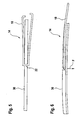
- FIG. 5 the fastening part 14 is shown with the bracket 18 of a wiper arm according to the invention together with a wiper blade 30.
- the wiper blade 30 is in this case designed as a so-called hinge-free wiper blade 30, which has no mounting frame.
- the wiper blade 30 is attached to the base 22 of the U-shaped bracket 18.
- the hinge part 14 is shown with the bracket 18 of the wiper arm and a joint-free wiper blade 30 in a side view.
- this has a reverse keyhole-like opening, so that the wiper blade 30 can be easily clipped into the base 22 of the U-shaped bracket 18.
- the bracket 18 has in this side view beyond a slight bend perpendicular to the plane of movement of the wiper arm 10.
- the joint part 14 is in a working position in which the bracket 18 and thus the struts 20 are biased.
- This working position lies between the first rest position RP1, which in the mounted state is typically located inside the motor vehicle or behind the disc and an axis which results from the extension of the two openings in the fastening part towards the base ( FIG. 2b ).
- the working point AP In the work area AB1 is the working point AP.
- the shorter strut 20 is slightly compressed, or slightly bent, resulting in a bias that pushes the struts 20 in the direction of the rest position RP1. This causes a force on the wiper blade 30 and presses it on the disc.
- the struts 20 and bracket 18 are typically bent from a simple round bar. Of course, other profiles, such as a rectangular steel can be used here. In simpler embodiments, the bracket 18 may also be made of plastic or other material.
- the base 22 of the temple 18 can, as in the Figures 1 and 2 represented, round, ie radius-shaped or level ( FIG. 5 ) be formed. This depends only on the attachment mechanism with which the wiper blade 30 is hinged to the bracket 18.
- the base 22 may be formed as a block in which the struts 20 are individually inserted. The struts 20 are then just not connected to each other as a bracket. Of course, the wiper blade 30 may also be secured elsewhere between the two struts 20. The base 22 is then defined by this attachment point.
- the fastening part 12 is made of plastic or in a metal casting or die casting process.
- the fixing member 12 may also be formed as a stamped and bent part of sheet metal.
Landscapes
- Engineering & Computer Science (AREA)
- Mechanical Engineering (AREA)
- Pivots And Pivotal Connections (AREA)
- Cleaning In General (AREA)
- Body Structure For Vehicles (AREA)
Claims (9)
- Bras d'essuie-glace (10), en particulier pour un dispositif d'essuie-glace d'un véhicule automobile, comprenant au moins :- une partie de fixation (12) pour la fixation à un arbre d'essuie-glace du dispositif d'essuie-glace,- une partie d'articulation (14) à laquelle peut être articulée un balai d'essuie-glace (30), qui, lors du fonctionnement du dispositif d'essuie-glace dans un plan de déplacement, peut glisser sur une vitre du véhicule automobile,- la partie d'articulation (14) étant formée essentiellement par deux montants (20) qui présentent chacun deux extrémités,- une extrémité respective étant connectée directement ou indirectement à la partie de fixation (12),- l'autre extrémité respective pouvant être connectée directement ou indirectement au balai d'essuie-glace (30),caractérisé en ce que- la longueur des montants (20) est choisie de telle sorte qu'un montant (20) soit un peu plus long que l'autre, de sorte que ceux-ci débouchent le long de l'étendue longitudinale du bras d'essuie-glace (10) ou de la partie de fixation (12) dans différents endroits dans la partie de fixation (12).
- Bras d'essuie-glace (10) selon la revendication 1, caractérisé en ce que les deux montants (20) sont formés par des branches d'un arceau (18) essentiellement en forme de U de configuration essentiellement allongée, qui comprend une base (22) et les deux branches, et en ce que le balai d'essuie-glace (30) peut être connecté directement ou indirectement à la base (22).
- Bras d'essuie-glace (10) selon l'une quelconque des revendications précédentes, caractérisé en ce que la partie d'articulation (14) peut être déplacée dans un plan de déplacement dans le plan de rabattement essentiellement vertical.
- Bras d'essuie-glace (10) selon la revendication 3, caractérisé en ce que la partie d'articulation peut être rabattue entre au moins deux positions de repos (RP1, RP2) en surmontant une force de type ressort.
- Bras d'essuie-glace (10) selon l'une quelconque des revendications précédentes, caractérisé en ce que le bras d'essuie-glace (10) se trouve pendant le fonctionnement dans une position de travail (AP) dans laquelle les montants (20) sont précontraints de telle sorte que le balai d'essuie-glace (30) soit pressé contre la vitre.
- Bras d'essuie-glace (10) selon l'une quelconque des revendications 3 à 5, caractérisé en ce que les premières extrémités des montants (20) connectées à la partie de fixation (12) débouchent, par rapport au plan de déplacement à différentes hauteurs, notamment dans la partie de fixation (12).
- Bras d'essuie-glace (10) selon l'une quelconque des revendications 3 à 6, caractérisé en ce que les premières extrémités des montants (20) sont cintrées vers l'intérieur approximativement parallèlement à la base (22) et viennent en prise comme des pinces dans des ouvertures (26) dans la partie de fixation (12).
- Bras d'essuie-glace (10) selon la revendication 7, caractérisé en ce que les ouvertures (26) dans la partie de fixation (12) sont renforcées par des douilles (28).
- Bras d'essuie-glace (10) selon l'une quelconque des revendications précédentes, caractérisé en ce que le balai d'essuie-glace (30) présente, dans l'état détendu, une flexion perpendiculairement au plan de déplacement.
Applications Claiming Priority (2)
| Application Number | Priority Date | Filing Date | Title |
|---|---|---|---|
| DE10345803A DE10345803A1 (de) | 2003-09-30 | 2003-09-30 | Wischerarm, insbesondere für eine Scheibenwischvorrichtung eines Kraftfahrzeugs |
| PCT/DE2004/000700 WO2005042318A1 (fr) | 2003-09-30 | 2004-04-03 | Bras d'essuie-glace, en particulier pour dispositif essuie-glace d'un vehicule automobile |
Publications (2)
| Publication Number | Publication Date |
|---|---|
| EP1670666A1 EP1670666A1 (fr) | 2006-06-21 |
| EP1670666B1 true EP1670666B1 (fr) | 2009-09-23 |
Family
ID=34306202
Family Applications (1)
| Application Number | Title | Priority Date | Filing Date |
|---|---|---|---|
| EP04725603A Expired - Lifetime EP1670666B1 (fr) | 2003-09-30 | 2004-04-03 | Bras d'essuie-glace, en particulier pour dispositif essuie-glace d'un vehicule automobile |
Country Status (6)
| Country | Link |
|---|---|
| EP (1) | EP1670666B1 (fr) |
| KR (1) | KR101067458B1 (fr) |
| CN (1) | CN1816473B (fr) |
| DE (2) | DE10345803A1 (fr) |
| ES (1) | ES2332786T3 (fr) |
| WO (1) | WO2005042318A1 (fr) |
Families Citing this family (5)
| Publication number | Priority date | Publication date | Assignee | Title |
|---|---|---|---|---|
| DE102010062992A1 (de) * | 2010-12-14 | 2012-06-14 | Robert Bosch Gmbh | Wischerabdeckung |
| DE102014201829A1 (de) | 2014-02-03 | 2015-08-06 | Robert Bosch Gmbh | Scheibenwischvorrichtung |
| DE102017208371A1 (de) * | 2017-05-18 | 2018-11-22 | Robert Bosch Gmbh | Wischarmvorrichtung |
| DE102017218126A1 (de) | 2017-10-11 | 2019-04-11 | Robert Bosch Gmbh | Wischhebel, insbesondere für eine Scheibe eines Kraftfahrzeugs |
| DE102017218128A1 (de) | 2017-10-11 | 2019-04-11 | Robert Bosch Gmbh | Wischhebel, insbesondere für eine Scheibe eines Kraftfahrzeugs |
Family Cites Families (8)
| Publication number | Priority date | Publication date | Assignee | Title |
|---|---|---|---|---|
| US2094732A (en) * | 1931-11-14 | 1937-10-05 | John W Anderson | Windshield wiper |
| US2043218A (en) * | 1931-11-14 | 1936-06-09 | John W Anderson | Windshield wiper |
| DE2812412A1 (de) * | 1978-03-22 | 1979-09-27 | Rau Swf Autozubehoer | Scheibenwischer, insbesondere fuer kraftfahrzeuge |
| FR2452403A1 (fr) * | 1979-03-29 | 1980-10-24 | Morette Jacques | Essuie-glace double pour vehicule |
| DE10052616A1 (de) * | 2000-10-24 | 2002-05-08 | Bosch Gmbh Robert | Wischarm |
| DE50109834D1 (de) * | 2000-11-18 | 2006-06-22 | Bosch Gmbh Robert | Vorrichtung zum lösbaren verbinden eines wischblatts zum reinigen von scheiben insbesondere von kraftfahrzeugen mit einem angetriebenen wischerarm |
| DE10227781B4 (de) * | 2002-06-21 | 2013-11-28 | Robert Bosch Gmbh | Scheibenwischvorrichtung |
| US6813802B2 (en) * | 2002-06-28 | 2004-11-09 | Valeo Electrical Systems, Inc. | Prestressed wiper arm |
-
2003
- 2003-09-30 DE DE10345803A patent/DE10345803A1/de not_active Ceased
-
2004
- 2004-04-03 DE DE502004010127T patent/DE502004010127D1/de not_active Expired - Lifetime
- 2004-04-03 WO PCT/DE2004/000700 patent/WO2005042318A1/fr not_active Ceased
- 2004-04-03 CN CN2004800186626A patent/CN1816473B/zh not_active Expired - Fee Related
- 2004-04-03 EP EP04725603A patent/EP1670666B1/fr not_active Expired - Lifetime
- 2004-04-03 ES ES04725603T patent/ES2332786T3/es not_active Expired - Lifetime
- 2004-04-03 KR KR1020057021846A patent/KR101067458B1/ko not_active Expired - Fee Related
Also Published As
| Publication number | Publication date |
|---|---|
| EP1670666A1 (fr) | 2006-06-21 |
| CN1816473B (zh) | 2011-06-15 |
| WO2005042318A1 (fr) | 2005-05-12 |
| DE10345803A1 (de) | 2005-04-14 |
| DE502004010127D1 (de) | 2009-11-05 |
| ES2332786T3 (es) | 2010-02-12 |
| KR20060064563A (ko) | 2006-06-13 |
| KR101067458B1 (ko) | 2011-09-27 |
| CN1816473A (zh) | 2006-08-09 |
Similar Documents
| Publication | Publication Date | Title |
|---|---|---|
| EP1833707B1 (fr) | Systeme d'essuie-glace | |
| EP1098796B1 (fr) | Systeme d'essuie-glace pour vehicules automobiles | |
| DE10227781B4 (de) | Scheibenwischvorrichtung | |
| EP1332075B1 (fr) | Dispositif de connexion articulee amovible d'un balai d'essuie-glace destine au nettoyage de vitres avec un bras d'essuie-glace | |
| EP1461235B1 (fr) | Essuie-glace monobras | |
| EP1519862B1 (fr) | Balai d'essuie-glace | |
| EP1363816B1 (fr) | Bras d'essuie-glace pourvu d'une raclette reliee de maniere articulee | |
| EP1501710B1 (fr) | Balai d'essuie-glace | |
| DE102005048344A1 (de) | Scheibenwischerarm | |
| DE102008000933A1 (de) | Vorrichtung zum gelenkigen Verbinden eines Wischblatts mit einem Wischarm | |
| EP0923468B1 (fr) | Dispositif de liaison d'une raclette d'essuie-glace a un bras de monture d'essuie-glace | |
| DE19951440A1 (de) | Wischarm für ein Fahrzeug | |
| EP1670666B1 (fr) | Bras d'essuie-glace, en particulier pour dispositif essuie-glace d'un vehicule automobile | |
| EP1575813B1 (fr) | Ensemble bras d'essuie-glace comportant un bras d'essuie-glace et une raclette d'essuie-glace | |
| DE10052616A1 (de) | Wischarm | |
| DE102015221910A1 (de) | Wischarmvorrichtung | |
| EP1720749B1 (fr) | Bras de dispositif d'essuie-glace | |
| DE102005046653A1 (de) | Scheibenwischvorrichtung, insbesondere für ein Kraftfahrzeug | |
| DE19811859B4 (de) | Wischervorrichtung | |
| DE10333082B4 (de) | Wischblatt für Fahrzeugscheiben | |
| DE102007061377A1 (de) | Scheibenwischerarm | |
| DE10118010B4 (de) | Außenrückspiegel mit schwenkbar gelagertem Spiegelkopf | |
| EP1462328B1 (fr) | Dispositif d'articulation d'un bras d'essuie-glace | |
| DE102013226351A1 (de) | Wischerarm und Wischvorrichtung | |
| EP1727716B1 (fr) | Bras essuie-glace pour un dispositif d'essuie-glace |
Legal Events
| Date | Code | Title | Description |
|---|---|---|---|
| PUAI | Public reference made under article 153(3) epc to a published international application that has entered the european phase |
Free format text: ORIGINAL CODE: 0009012 |
|
| 17P | Request for examination filed |
Effective date: 20060502 |
|
| AK | Designated contracting states |
Kind code of ref document: A1 Designated state(s): DE ES FR GB |
|
| DAX | Request for extension of the european patent (deleted) | ||
| RBV | Designated contracting states (corrected) |
Designated state(s): DE ES FR GB |
|
| 17Q | First examination report despatched |
Effective date: 20081120 |
|
| GRAP | Despatch of communication of intention to grant a patent |
Free format text: ORIGINAL CODE: EPIDOSNIGR1 |
|
| GRAS | Grant fee paid |
Free format text: ORIGINAL CODE: EPIDOSNIGR3 |
|
| GRAA | (expected) grant |
Free format text: ORIGINAL CODE: 0009210 |
|
| AK | Designated contracting states |
Kind code of ref document: B1 Designated state(s): DE ES FR GB |
|
| REG | Reference to a national code |
Ref country code: GB Ref legal event code: FG4D Free format text: NOT ENGLISH |
|
| REF | Corresponds to: |
Ref document number: 502004010127 Country of ref document: DE Date of ref document: 20091105 Kind code of ref document: P |
|
| REG | Reference to a national code |
Ref country code: ES Ref legal event code: FG2A Ref document number: 2332786 Country of ref document: ES Kind code of ref document: T3 |
|
| PLBE | No opposition filed within time limit |
Free format text: ORIGINAL CODE: 0009261 |
|
| STAA | Information on the status of an ep patent application or granted ep patent |
Free format text: STATUS: NO OPPOSITION FILED WITHIN TIME LIMIT |
|
| 26N | No opposition filed |
Effective date: 20100624 |
|
| REG | Reference to a national code |
Ref country code: FR Ref legal event code: PLFP Year of fee payment: 13 |
|
| REG | Reference to a national code |
Ref country code: FR Ref legal event code: PLFP Year of fee payment: 14 |
|
| REG | Reference to a national code |
Ref country code: FR Ref legal event code: PLFP Year of fee payment: 15 |
|
| PGFP | Annual fee paid to national office [announced via postgrant information from national office to epo] |
Ref country code: DE Payment date: 20190627 Year of fee payment: 16 |
|
| PGFP | Annual fee paid to national office [announced via postgrant information from national office to epo] |
Ref country code: FR Payment date: 20200421 Year of fee payment: 17 Ref country code: ES Payment date: 20200516 Year of fee payment: 17 |
|
| PGFP | Annual fee paid to national office [announced via postgrant information from national office to epo] |
Ref country code: GB Payment date: 20200423 Year of fee payment: 17 |
|
| REG | Reference to a national code |
Ref country code: DE Ref legal event code: R119 Ref document number: 502004010127 Country of ref document: DE |
|
| PG25 | Lapsed in a contracting state [announced via postgrant information from national office to epo] |
Ref country code: DE Free format text: LAPSE BECAUSE OF NON-PAYMENT OF DUE FEES Effective date: 20201103 |
|
| GBPC | Gb: european patent ceased through non-payment of renewal fee |
Effective date: 20210403 |
|
| PG25 | Lapsed in a contracting state [announced via postgrant information from national office to epo] |
Ref country code: GB Free format text: LAPSE BECAUSE OF NON-PAYMENT OF DUE FEES Effective date: 20210403 Ref country code: FR Free format text: LAPSE BECAUSE OF NON-PAYMENT OF DUE FEES Effective date: 20210430 |
|
| REG | Reference to a national code |
Ref country code: ES Ref legal event code: FD2A Effective date: 20220629 |
|
| PG25 | Lapsed in a contracting state [announced via postgrant information from national office to epo] |
Ref country code: ES Free format text: LAPSE BECAUSE OF NON-PAYMENT OF DUE FEES Effective date: 20210404 |