EP1671801A2 - Bilderzeugungsverfahren und -vorrichtung - Google Patents
Bilderzeugungsverfahren und -vorrichtung Download PDFInfo
- Publication number
- EP1671801A2 EP1671801A2 EP05111931A EP05111931A EP1671801A2 EP 1671801 A2 EP1671801 A2 EP 1671801A2 EP 05111931 A EP05111931 A EP 05111931A EP 05111931 A EP05111931 A EP 05111931A EP 1671801 A2 EP1671801 A2 EP 1671801A2
- Authority
- EP
- European Patent Office
- Prior art keywords
- image
- heaters
- medium
- print head
- thermal print
- Prior art date
- Legal status (The legal status is an assumption and is not a legal conclusion. Google has not performed a legal analysis and makes no representation as to the accuracy of the status listed.)
- Withdrawn
Links
Images



Classifications
-
- B—PERFORMING OPERATIONS; TRANSPORTING
- B41—PRINTING; LINING MACHINES; TYPEWRITERS; STAMPS
- B41J—TYPEWRITERS; SELECTIVE PRINTING MECHANISMS, i.e. MECHANISMS PRINTING OTHERWISE THAN FROM A FORME; CORRECTION OF TYPOGRAPHICAL ERRORS
- B41J2/00—Typewriters or selective printing mechanisms characterised by the printing or marking process for which they are designed
- B41J2/315—Typewriters or selective printing mechanisms characterised by the printing or marking process for which they are designed characterised by selective application of heat to a heat sensitive printing or impression-transfer material
- B41J2/32—Typewriters or selective printing mechanisms characterised by the printing or marking process for which they are designed characterised by selective application of heat to a heat sensitive printing or impression-transfer material using thermal heads
-
- B—PERFORMING OPERATIONS; TRANSPORTING
- B41—PRINTING; LINING MACHINES; TYPEWRITERS; STAMPS
- B41J—TYPEWRITERS; SELECTIVE PRINTING MECHANISMS, i.e. MECHANISMS PRINTING OTHERWISE THAN FROM A FORME; CORRECTION OF TYPOGRAPHICAL ERRORS
- B41J2/00—Typewriters or selective printing mechanisms characterised by the printing or marking process for which they are designed
- B41J2/315—Typewriters or selective printing mechanisms characterised by the printing or marking process for which they are designed characterised by selective application of heat to a heat sensitive printing or impression-transfer material
- B41J2/32—Typewriters or selective printing mechanisms characterised by the printing or marking process for which they are designed characterised by selective application of heat to a heat sensitive printing or impression-transfer material using thermal heads
- B41J2/35—Typewriters or selective printing mechanisms characterised by the printing or marking process for which they are designed characterised by selective application of heat to a heat sensitive printing or impression-transfer material using thermal heads providing current or voltage to the thermal head
- B41J2/355—Control circuits for heating-element selection
-
- B—PERFORMING OPERATIONS; TRANSPORTING
- B41—PRINTING; LINING MACHINES; TYPEWRITERS; STAMPS
- B41J—TYPEWRITERS; SELECTIVE PRINTING MECHANISMS, i.e. MECHANISMS PRINTING OTHERWISE THAN FROM A FORME; CORRECTION OF TYPOGRAPHICAL ERRORS
- B41J2/00—Typewriters or selective printing mechanisms characterised by the printing or marking process for which they are designed
- B41J2/385—Typewriters or selective printing mechanisms characterised by the printing or marking process for which they are designed characterised by selective supply of electric current or selective application of magnetism to a printing or impression-transfer material
- B41J2/42—Typewriters or selective printing mechanisms characterised by the printing or marking process for which they are designed characterised by selective supply of electric current or selective application of magnetism to a printing or impression-transfer material for heating selectively
Definitions
- the present invention relates to forming an image, particularly but not exclusively to an apparatus and method for driving a thermal print head to print an image.
- an image forming apparatus converts a document produced by a user using a computer application, or an image photographed with, for instance, a digital camera, into encoded data.
- the image forming apparatus outputs the encoded data onto printing media making it visible to the user.
- thermal printer One such image forming apparatus is a thermal printer.
- thermal printer There are, in general, two types of thermal printer, a first type which uses thermal paper that displays an image when exposed to heat, and a second type which typically uses an ink ribbon which transfers ink to a printing medium such as paper when the ribbon is exposed to heat.
- Thermal printers apply heat to a medium to be printed using a thermal print head.
- the thermal print head includes a plurality of heaters, also referred to as recording elements, each arranged across the width of a printing medium and having a predetermined resistance R.
- the heaters supply heat to the printing medium in response to application of a predetermined voltage, VHD.
- the number of heaters in the thermal print head can be increased. Accordingly, the number of control signals required to control operation of the thermal print head increases as the number of heaters increases.
- An embodiment of the present invention provides a method of driving a thermal print head by dividing a plurality of heaters within the thermal print head into a number of phases.
- the heaters are sequentially activated to consecutively print at least two images in order to reduce power consumption while printing.
- a method of driving a thermal print head includes dividing heaters, which consecutively print at least two colour images, into a predetermined number of groups, including multiple heaters.
- the method further includes; driving the heaters in each of the groups to sequentially print a first colour image.
- the thermal print head may rotate to face first and second surfaces of the print medium.
- the thermal print head may consecutively print a yellow image and a magenta image on the medium's first surface by applying heat to the first surface.
- a cyan image may be printed on the second surface of the medium by applying heat to the second surface.
- a method of driving a thermal print head that includes dividing heaters into a predetermined number of groups, including multiple heaters, to consecutively print images. The method further includes driving the heaters in each of the groups to sequentially print a first image and then print a second image at a different time.
- the printed images are colour.
- the thermal print head may rotate to face first and second surfaces of the print medium.
- the first image may be yellow and the second image magenta.
- the heaters in each group may be driven to sequentially print the yellow image at predetermined intervals.
- the predetermined interval may be a unit of time during which the heater applies heat to the medium.
- a latch signal input to the thermal print head may be delayed as much as the predetermined interval so that the heaters can print the yellow image at the predetermined intervals.
- an image forming apparatus that includes a data input unit to receive image data of an image that is to be printed; a control unit to generate control signals to drive heaters in response to the input image data; and a thermal print head having a plurality of heaters that are divided into a predetermined number of groups.
- the print head is configured to drive the heaters in response to the control signals.
- the control unit generates control signals to control the heaters and print at least two colour images consecutively.
- the heaters of each group are controlled to sequentially print a first colour image.
- the image forming apparatus may further include a location adjusting unit to rotate the thermal print head so that the print head faces a first or a second surface of the print medium.
- the control unit may generate control signals to control the heaters in each group to sequentially print a first colour image, then print a second colour image at a time different than when the first colour image was printed.
- the control unit may generate signals to control the heaters in each group to sequentially print the yellow image at predetermined intervals.
- the predetermined interval may be a unit of time during which the heater applies heat to the print medium.
- the control unit may generate a latch signal to cause delay equivalent to a predetermined interval so that the heaters can print a yellow image during the predetermined interval.
- the method of driving the thermal print head may be embodied in a computer readable medium having stored thereon instructions for driving a thermal print head in accordance with methods and aspects of the present invention.
- FIG. 1 depicts a cross-section of a heat-sensitive medium 220 according to an embodiment of the present invention.
- the medium 220 includes a base sheet 11, which has ink layers of predetermined colours formed on first and second surfaces 10a and 10b.
- the ink layers are of different colours. For example, yellow (Y) and magenta (M) layers are sequentially stacked on the first surface 10a, and a cyan (C) layer is formed on the second surface 10b.
- the base sheet 11 may be transparent.
- a reflective layer 13 formed on the bottom of the second surface 10b reflects light onto a colour image formed on the first surface 10a.
- the yellow image may be produced by the application of a relatively large amount of heat to the medium 220 over a short time period.
- the magenta image may be produced when a small amount of heat is applied to the medium 220 over a relatively long period.
- Figure 2 shows a view of an image forming apparatus that prints two colour images consecutively by applying heat to a medium 220.
- the image forming apparatus includes a platen roller 205, a thermal print head 210, a driving unit 230, a driving roller 235, an idle roller 240, an edge detecting sensor 245, a medium guide 250, a discharge unit 260, a discharge slave roller 265, a discharge roller 270, a pickup roller 280, and a medium storage unit 290.
- the pickup roller 280 picks up a printing medium 220, for example thermal paper, from the medium storage unit 290 and transports the medium 220 along a first path, illustrated in Figure 2, to the driving roller 235 and the idle roller 240.
- the driving roller 235 and the idle roller 240 transport the medium 220 along a second path in a direction illustrated by the arrows labelled 'B', which is opposite to the direction in which the medium 220 moves when an image is being printed.
- the driving roller 235 and the idle roller 240 transport the medium 220 back along the second path in a printing direction F.
- a yellow image and a magenta image are consecutively formed on the first surface 10a of the medium 220 by the thermal print head 210 continuously applying heat thereto.
- the medium 220 travels within a third path before returning to the second path, where it is transported in the direction B to print a cyan image on the second surface 10b of the medium 220 after the yellow and magenta images have been formed on the first surface 10a of medium 220. Once printing is completed, the medium 220 is transported in the printing direction F along the third path to be discharged.
- the medium guide 250 guides the medium 220 between the first, second, or third paths.
- the edge detecting sensor 245 is used to determine the location of the medium 220.
- the thermal print head 210 is placed at a location indicated by arrow D when the thermal print head 210 is required to continuously apply heat to the first surface 10a of the medium 220 to print yellow and magenta images.
- the thermal print head 210 may be placed at a location indicated by arrow C when printing the cyan image on the second surface 10b of medium 220.
- the location of thermal print head 210 may be changed by rotating the thermal print head 210 about an axis of the platen roller 205.
- FIG. 3 is a block diagram of an image forming apparatus according to an embodiment of the present invention.
- the image forming apparatus includes a data input unit 300, a control unit 310, and a thermal print head 320.
- the data input unit 300 receives image data from, for example, a personal computer (PC), a digital camera, or a personal digital assistant (PDA).
- PC personal computer
- PDA personal digital assistant
- the control unit 310 generates control signals to control the operation of the thermal print head 320 according to the input image data.
- the thermal print head 320 receives control signals from the control unit 310 and drives a plurality of heaters 400, 410, 420, shown in Figure 4, to apply heat to the medium 220 to print an image.
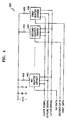
- FIG 4 is a schematic diagram of the thermal print head 320 illustrated in Figure 3.
- the thermal print head 320 includes a plurality of heaters 400, 410, 420, and a plurality of heater drivers 430, 440, 450.
- the plurality of heaters 400, 410, and 420 apply heat to the medium 220, and are driven by the corresponding plurality of heater drivers 430, 440, 450.
- a 3-inch, 300 dpi, thermal print head includes 900 heaters that are turned on/off by 900 corresponding heater drivers.
- the 900 heaters generate heat as the result of an applied voltage VHD.
- Figure 5 is a timing diagram of the control signals that are input during one gradation to drive the heaters 400, 410, 420 of the thermal print head 320.
- Image data including information regarding the on/off state of the heaters 400, 410, 420 is synchronized to a clock signal, and inputted to shift registers (not shown) within the heater drivers 430, 440, 450.
- the image data is temporarily stored in flip-flops (not shown) within the heater drivers 430, 440, 450 in response to a latch signal, which sets the flip-flops to output signals to drive the heaters.
- the time W is indicative of the time over which each of the heaters 400, 410, 420 is required to apply heat to the medium 220 once.
- Figure 6 is a diagram depicting the consecutive printing of yellow and magenta images, in which the plurality of heaters 400, 410, 420 is divided into 12 phases according to an embodiment of the present invention.
- An image is formed diagonally on the medium 220 as the medium 220 is moved past the thermal print head 210.
- the plurality of heaters 400, 410, 420 is divided into groups of 12, and an image is printed in 12 phases so that the printing time of a first colour, which in some embodiments is yellow (Y), does not overlap with the printing time of a second colour, which in some embodiments is magenta (M).
- Y yellow
- M magenta
- Figure 7 is a diagram depicting the consecutive printing of yellow and magenta images by dividing the plurality of heaters 400, 410, 420 into 12 groups according to another embodiment of the present invention.
- Figure 7 illustrates a single group of the plurality of groups of heaters 400, 410, 420. Hatched portions each illustrate an area to which one of the heaters 400, 410, 420 applies heat to the medium 220.
- the heater consecutively applies heat to the medium 220 four times to print a yellow image, and the heater heats the medium 220 over four cycles, each cycle having a portion in which the heater is 'on' and a portion in which the heater is 'off, at a predetermined distance to print a magenta image.
- miniT denotes a unit of time during which the heater applies heat once to the medium 220
- MAGENTA duty denotes a cycle during which the heater applies heat to the medium 220 to print a magenta image. As illustrated in Figure 7, the magenta duty is 4 ⁇ miniT.
- a maximum of five heaters out of the twelve in each group is powered at any one time.
- the power consumed by the heaters 400, 410, 420 during the heating time is P and the thermal print head 320 includes 1200 heaters, a maximum power of 5 ⁇ P ⁇ 100 is required to drive the thermal print head 320. Therefore, the thermal print head 320 can be driven with a power of about 42% of 1200 ⁇ P, which is the power consumed in simultaneously driving all of the heaters.
- Figure 8 depicts the consecutive printing of yellow and magenta images, in which the plurality of heaters 400, 410, 420 is divided into 12 phases according to another embodiment of the present invention.
- two adjacent heaters print a magenta image, which is the second colour image to be printed in the previous embodiment illustrated in Figure 7.
- the magenta image is printed after an interval miniT between a time when printing a yellow image is finished and a time when the magenta image starts to be printed.
- the printing time for the magenta image does not overlap with the printing time for the yellow image.
- commencement of the interval over which a second heater is powered to produce a yellow dot on the medium 220 is delayed until after the first burst of power to produce a magenta image has been applied to a first heater.
- a maximum of two heaters out of the twelve heaters in each group is powered at any one time.
- the power consumed by the heaters 400, 410, 420 during the heating time is P
- the thermal print head 320 includes 1200 heaters
- a maximum power of 2 ⁇ P ⁇ 100 is required to drive the thermal print head 320. Therefore, the thermal print head 320 can be driven with a power of about 16.7% of 1200 X P, which is the power consumed in simultaneously driving all of the heaters 400, 410, 420.
- offset values for controlling the power 'on' time of each heater 400, 410, or 420 may be adjusted according to a particular sequence for driving the heaters 400, 410, 420.
- the sequence of powering a plurality of heaters is arranged in 12 phases and the heaters are sequentially driven to print an image on a medium when printing more than two colour images consecutively using the thermal print head.
- a power consumed in driving the heaters can be reduced.
- a computer readable medium is any data storage device that can store data and can thereafter be read by a computer system.
- Examples of a computer readable medium include read-only memory (ROM), random-access memory (RAM), CD-ROMs, magnetic tapes, floppy disks, optical data storage devices, and data signals such as carrier waves for data transmission.
- the computer readable medium can also be distributed over network coupled computer systems so that the computer readable instructions are stored and executed in a distributed fashion. Also, functional programs, codes, and code segments for accomplishing the present invention can be easily construed by programmers skilled in the art to which the present invention pertains.
- the embodiments above illustrate the thermal print head printing a yellow image and a magenta image consecutively, and then printing a cyan image.
- the present invention can be applied in consecutive printing of any two of a yellow image, a magenta image, and a cyan image, or when consecutively printing more than three colour images.
Landscapes
- Electronic Switches (AREA)
Applications Claiming Priority (1)
| Application Number | Priority Date | Filing Date | Title |
|---|---|---|---|
| KR1020040106540A KR100788658B1 (ko) | 2004-12-15 | 2004-12-15 | 열전사헤드의 구동 방법 및 그를 이용한 화상 형성 장치 |
Publications (2)
| Publication Number | Publication Date |
|---|---|
| EP1671801A2 true EP1671801A2 (de) | 2006-06-21 |
| EP1671801A3 EP1671801A3 (de) | 2009-03-11 |
Family
ID=35884018
Family Applications (1)
| Application Number | Title | Priority Date | Filing Date |
|---|---|---|---|
| EP05111931A Withdrawn EP1671801A3 (de) | 2004-12-15 | 2005-12-09 | Bilderzeugungsverfahren und -vorrichtung |
Country Status (4)
| Country | Link |
|---|---|
| US (1) | US7388596B2 (de) |
| EP (1) | EP1671801A3 (de) |
| KR (1) | KR100788658B1 (de) |
| CN (1) | CN1789003A (de) |
Cited By (1)
| Publication number | Priority date | Publication date | Assignee | Title |
|---|---|---|---|---|
| WO2008145493A1 (de) * | 2007-05-30 | 2008-12-04 | Continental Automotive Gmbh | Verfahren und vorrichtung zum betreiben einer thermodruckereinheit |
Families Citing this family (6)
| Publication number | Priority date | Publication date | Assignee | Title |
|---|---|---|---|---|
| US7830405B2 (en) | 2005-06-23 | 2010-11-09 | Zink Imaging, Inc. | Print head pulsing techniques for multicolor printers |
| CA2446880C (en) * | 2001-05-30 | 2010-08-03 | Polaroid Corporation | Thermal imaging system |
| US8377844B2 (en) * | 2001-05-30 | 2013-02-19 | Zink Imaging, Inc. | Thermally-insulating layers and direct thermal imaging members containing same |
| US7791626B2 (en) * | 2001-05-30 | 2010-09-07 | Zink Imaging, Inc. | Print head pulsing techniques for multicolor printers |
| US7388686B2 (en) * | 2003-02-25 | 2008-06-17 | Zink Imaging, Llc | Image stitching for a multi-head printer |
| CN109703205B (zh) * | 2018-12-29 | 2020-12-22 | 厦门汉印电子技术有限公司 | 一种打印方法、装置、打印机和存储介质 |
Family Cites Families (15)
| Publication number | Priority date | Publication date | Assignee | Title |
|---|---|---|---|---|
| JPS60122169A (ja) | 1983-12-06 | 1985-06-29 | Shinko Electric Co Ltd | 高密度ドツトプリンタ |
| JPH0683349B2 (ja) * | 1985-01-09 | 1994-10-19 | 株式会社リコー | 感熱記録方法 |
| JPS63265668A (ja) | 1987-04-24 | 1988-11-02 | Nec Home Electronics Ltd | 印刷装置 |
| JPH082658B2 (ja) * | 1988-01-29 | 1996-01-17 | ローム株式会社 | 二色発色感熱紙の印字方法 |
| JPH0243060A (ja) * | 1988-04-07 | 1990-02-13 | Ricoh Co Ltd | サーマルヘッド駆動装置 |
| JPH02117856A (ja) | 1988-10-27 | 1990-05-02 | Kyocera Corp | サーマルヘッド |
| US5075701A (en) * | 1990-07-17 | 1991-12-24 | Matsushita Electric Industrial Co., Ltd. | Thermal recording head having group-wise actuable heating elements |
| JPH04220372A (ja) | 1990-12-20 | 1992-08-11 | Fujitsu Ltd | ラインドットサーマルプリンタの駆動方式 |
| JP3408551B2 (ja) | 1992-01-31 | 2003-05-19 | グラフテック株式会社 | サーマルヘッド制御装置 |
| JP3333596B2 (ja) | 1993-08-19 | 2002-10-15 | 株式会社リコー | 熱転写式記録装置 |
| JPH09193438A (ja) | 1996-01-19 | 1997-07-29 | Nec Home Electron Ltd | 熱転写記録装置 |
| US6296405B1 (en) * | 2000-01-04 | 2001-10-02 | International Business Machines Corporation | Duplex check printer using a print mechanism pivoted between document paths |
| JP2001232841A (ja) * | 2000-02-21 | 2001-08-28 | Alps Electric Co Ltd | ラインサーマルヘッドの通電制御方法 |
| US7198419B2 (en) * | 2003-10-08 | 2007-04-03 | Samsung Electronics Co., Ltd. | Apparatus and method of performing double-sided printing |
| US7179002B2 (en) * | 2003-12-31 | 2007-02-20 | Samsung Electronics Co., Ltd. | Thermal image forming apparatus |
-
2004
- 2004-12-15 KR KR1020040106540A patent/KR100788658B1/ko not_active Expired - Fee Related
-
2005
- 2005-11-30 US US11/289,548 patent/US7388596B2/en not_active Expired - Fee Related
- 2005-12-09 EP EP05111931A patent/EP1671801A3/de not_active Withdrawn
- 2005-12-15 CN CNA2005101316110A patent/CN1789003A/zh active Pending
Cited By (1)
| Publication number | Priority date | Publication date | Assignee | Title |
|---|---|---|---|---|
| WO2008145493A1 (de) * | 2007-05-30 | 2008-12-04 | Continental Automotive Gmbh | Verfahren und vorrichtung zum betreiben einer thermodruckereinheit |
Also Published As
| Publication number | Publication date |
|---|---|
| KR20060067687A (ko) | 2006-06-20 |
| US7388596B2 (en) | 2008-06-17 |
| CN1789003A (zh) | 2006-06-21 |
| EP1671801A3 (de) | 2009-03-11 |
| KR100788658B1 (ko) | 2007-12-26 |
| US20060125908A1 (en) | 2006-06-15 |
Similar Documents
| Publication | Publication Date | Title |
|---|---|---|
| US6961075B2 (en) | Method and apparatus for thermal printing of longer length images by the use of multiple dye color patch triads or quads | |
| EP1671801A2 (de) | Bilderzeugungsverfahren und -vorrichtung | |
| US7477273B2 (en) | Method and device for adjusting alignment of image forming apparatus | |
| US7405745B2 (en) | Method of driving print head and image forming apparatus employing the same | |
| US5398050A (en) | Color thermal printing method and device capable of preventing underlying thermosensitive coloring layers from developing color | |
| CN107867080A (zh) | 打印装置、打印装置的控制方法及计算机可读的记录介质 | |
| EP1658982A2 (de) | Thermodruckkopf | |
| JP5836636B2 (ja) | 印刷装置及びその制御方法 | |
| JP2002347265A (ja) | 印刷装置 | |
| JPH0696300B2 (ja) | カラ−記録装置 | |
| JP2001063124A (ja) | サーマルラインプリンタおよびサーマルラインプリンタの駆動方法 | |
| JP2848573B2 (ja) | 記録装置及びファクシミリ装置 | |
| US6724411B2 (en) | Thermal printer with bi-directional print head movement and method thereof | |
| JP3310789B2 (ja) | カラー感熱プリント方法 | |
| JP2002178552A (ja) | マルチサーマルヘッド駆動方法およびマルチサーマルヘッドプリンタ | |
| JPH11268343A (ja) | 記録装置 | |
| JP2578953B2 (ja) | 熱転写記録装置及び該装置を用いたフアクシミリ装置 | |
| JPS61182373A (ja) | 転写型感熱記録装置 | |
| JPH01214459A (ja) | 印刷方法 | |
| JP2009039937A (ja) | プリンタ及び印刷制御方法 | |
| JPH09174897A (ja) | カラー感熱プリンタ | |
| JP2003276224A (ja) | 熱転写記録装置および熱転写記録方法 | |
| JPH07290747A (ja) | 熱転写型プリンタの駆動装置 | |
| JPH03244564A (ja) | 記録装置 | |
| JP2003276223A (ja) | 熱転写記録装置および熱転写記録方法 |
Legal Events
| Date | Code | Title | Description |
|---|---|---|---|
| PUAI | Public reference made under article 153(3) epc to a published international application that has entered the european phase |
Free format text: ORIGINAL CODE: 0009012 |
|
| AK | Designated contracting states |
Kind code of ref document: A2 Designated state(s): AT BE BG CH CY CZ DE DK EE ES FI FR GB GR HU IE IS IT LI LT LU LV MC NL PL PT RO SE SI SK TR |
|
| AX | Request for extension of the european patent |
Extension state: AL BA HR MK YU |
|
| PUAL | Search report despatched |
Free format text: ORIGINAL CODE: 0009013 |
|
| AK | Designated contracting states |
Kind code of ref document: A3 Designated state(s): AT BE BG CH CY CZ DE DK EE ES FI FR GB GR HU IE IS IT LI LT LU LV MC NL PL PT RO SE SI SK TR |
|
| AX | Request for extension of the european patent |
Extension state: AL BA HR MK YU |
|
| AKX | Designation fees paid | ||
| REG | Reference to a national code |
Ref country code: DE Ref legal event code: 8566 |
|
| STAA | Information on the status of an ep patent application or granted ep patent |
Free format text: STATUS: THE APPLICATION IS DEEMED TO BE WITHDRAWN |
|
| 18D | Application deemed to be withdrawn |
Effective date: 20090912 |