EP1671812A2 - Sitz für Radlagervorrichtung mit Kraftdämpfung - Google Patents
Sitz für Radlagervorrichtung mit Kraftdämpfung Download PDFInfo
- Publication number
- EP1671812A2 EP1671812A2 EP05077748A EP05077748A EP1671812A2 EP 1671812 A2 EP1671812 A2 EP 1671812A2 EP 05077748 A EP05077748 A EP 05077748A EP 05077748 A EP05077748 A EP 05077748A EP 1671812 A2 EP1671812 A2 EP 1671812A2
- Authority
- EP
- European Patent Office
- Prior art keywords
- flange
- support member
- vehicle
- sleeve
- mounting
- Prior art date
- Legal status (The legal status is an assumption and is not a legal conclusion. Google has not performed a legal analysis and makes no representation as to the accuracy of the status listed.)
- Withdrawn
Links
- 230000008878 coupling Effects 0.000 claims abstract description 5
- 238000010168 coupling process Methods 0.000 claims abstract description 5
- 238000005859 coupling reaction Methods 0.000 claims abstract description 5
- 230000004044 response Effects 0.000 abstract description 4
- 238000000034 method Methods 0.000 description 5
- 238000005096 rolling process Methods 0.000 description 5
- 230000008859 change Effects 0.000 description 2
- 238000003754 machining Methods 0.000 description 2
- 239000000463 material Substances 0.000 description 2
- 230000036316 preload Effects 0.000 description 2
- 230000008569 process Effects 0.000 description 2
- 230000000717 retained effect Effects 0.000 description 2
- 229910000677 High-carbon steel Inorganic materials 0.000 description 1
- 229910000831 Steel Inorganic materials 0.000 description 1
- 230000000712 assembly Effects 0.000 description 1
- 238000000429 assembly Methods 0.000 description 1
- 230000003247 decreasing effect Effects 0.000 description 1
- 238000005242 forging Methods 0.000 description 1
- 238000007373 indentation Methods 0.000 description 1
- 230000007246 mechanism Effects 0.000 description 1
- 238000012986 modification Methods 0.000 description 1
- 230000004048 modification Effects 0.000 description 1
- 230000035939 shock Effects 0.000 description 1
- 239000007787 solid Substances 0.000 description 1
- 239000010959 steel Substances 0.000 description 1
- 239000000725 suspension Substances 0.000 description 1
Images


Classifications
-
- F—MECHANICAL ENGINEERING; LIGHTING; HEATING; WEAPONS; BLASTING
- F16—ENGINEERING ELEMENTS AND UNITS; GENERAL MEASURES FOR PRODUCING AND MAINTAINING EFFECTIVE FUNCTIONING OF MACHINES OR INSTALLATIONS; THERMAL INSULATION IN GENERAL
- F16C—SHAFTS; FLEXIBLE SHAFTS; ELEMENTS OR CRANKSHAFT MECHANISMS; ROTARY BODIES OTHER THAN GEARING ELEMENTS; BEARINGS
- F16C35/00—Rigid support of bearing units; Housings, e.g. caps, covers
- F16C35/04—Rigid support of bearing units; Housings, e.g. caps, covers in the case of ball or roller bearings
- F16C35/06—Mounting or dismounting of ball or roller bearings; Fixing them onto shaft or in housing
- F16C35/067—Fixing them in a housing
-
- B—PERFORMING OPERATIONS; TRANSPORTING
- B60—VEHICLES IN GENERAL
- B60B—VEHICLE WHEELS; CASTORS; AXLES FOR WHEELS OR CASTORS; INCREASING WHEEL ADHESION
- B60B27/00—Hubs
-
- F—MECHANICAL ENGINEERING; LIGHTING; HEATING; WEAPONS; BLASTING
- F16—ENGINEERING ELEMENTS AND UNITS; GENERAL MEASURES FOR PRODUCING AND MAINTAINING EFFECTIVE FUNCTIONING OF MACHINES OR INSTALLATIONS; THERMAL INSULATION IN GENERAL
- F16C—SHAFTS; FLEXIBLE SHAFTS; ELEMENTS OR CRANKSHAFT MECHANISMS; ROTARY BODIES OTHER THAN GEARING ELEMENTS; BEARINGS
- F16C19/00—Bearings with rolling contact, for exclusively rotary movement
- F16C19/02—Bearings with rolling contact, for exclusively rotary movement with bearing balls essentially of the same size in one or more circular rows
- F16C19/14—Bearings with rolling contact, for exclusively rotary movement with bearing balls essentially of the same size in one or more circular rows for both radial and axial load
- F16C19/18—Bearings with rolling contact, for exclusively rotary movement with bearing balls essentially of the same size in one or more circular rows for both radial and axial load with two or more rows of balls
- F16C19/181—Bearings with rolling contact, for exclusively rotary movement with bearing balls essentially of the same size in one or more circular rows for both radial and axial load with two or more rows of balls with angular contact
- F16C19/183—Bearings with rolling contact, for exclusively rotary movement with bearing balls essentially of the same size in one or more circular rows for both radial and axial load with two or more rows of balls with angular contact with two rows at opposite angles
- F16C19/184—Bearings with rolling contact, for exclusively rotary movement with bearing balls essentially of the same size in one or more circular rows for both radial and axial load with two or more rows of balls with angular contact with two rows at opposite angles in O-arrangement
- F16C19/186—Bearings with rolling contact, for exclusively rotary movement with bearing balls essentially of the same size in one or more circular rows for both radial and axial load with two or more rows of balls with angular contact with two rows at opposite angles in O-arrangement with three raceways provided integrally on parts other than race rings, e.g. third generation hubs
-
- F—MECHANICAL ENGINEERING; LIGHTING; HEATING; WEAPONS; BLASTING
- F16—ENGINEERING ELEMENTS AND UNITS; GENERAL MEASURES FOR PRODUCING AND MAINTAINING EFFECTIVE FUNCTIONING OF MACHINES OR INSTALLATIONS; THERMAL INSULATION IN GENERAL
- F16C—SHAFTS; FLEXIBLE SHAFTS; ELEMENTS OR CRANKSHAFT MECHANISMS; ROTARY BODIES OTHER THAN GEARING ELEMENTS; BEARINGS
- F16C27/00—Elastic or yielding bearings or bearing supports, for exclusively rotary movement
- F16C27/04—Ball or roller bearings, e.g. with resilient rolling bodies
-
- F—MECHANICAL ENGINEERING; LIGHTING; HEATING; WEAPONS; BLASTING
- F16—ENGINEERING ELEMENTS AND UNITS; GENERAL MEASURES FOR PRODUCING AND MAINTAINING EFFECTIVE FUNCTIONING OF MACHINES OR INSTALLATIONS; THERMAL INSULATION IN GENERAL
- F16C—SHAFTS; FLEXIBLE SHAFTS; ELEMENTS OR CRANKSHAFT MECHANISMS; ROTARY BODIES OTHER THAN GEARING ELEMENTS; BEARINGS
- F16C2326/00—Articles relating to transporting
- F16C2326/01—Parts of vehicles in general
- F16C2326/02—Wheel hubs or castors
Definitions
- This invention relates to wheel bearing assemblies for supporting a wheel and, more particularly, to an apparatus and method for attenuating impact forces transmitted to ball bearings in a wheel bearing assembly.
- a wheel bearing assembly is used between a spindle and either a support member or a wheel hub (depending on the particular assembly configuration) for permitting relative rotation between the spindle and the support member or wheel hub.
- the vehicle wheel bearing assembly has become much more susceptible to damage resulting from side impact forces between the vehicle wheels and objects such as curbs. These side impact forces act in a direction generally parallel to the axis of the spindle and are transmitted to the bearing rolling elements (such as balls or rollers) and thence to the bearing raceways in which the rolling elements travel.
- the present invention provides a support member for a wheel bearing assembly.
- the support member has a central sleeve for securing bearing members therein, and a mounting flange extending from the central sleeve for securing the bearing assembly to a portion of a vehicle.
- the flange has a concave central portion coupled to the sleeve.
- the flange tapers down from the central portion into three, substantially equally angularly spaced-apart lobes projecting outwardly from the central portion.
- the junction between the central sleeve and the central portion of the flange has a radius formed therealong to help relieve any stress concentrations at the junction during flexing of the flange.
- One or more substantially flat, coplanar bearing surfaces are also formed along each of the lobes.
- the bearing surfaces abut the vehicle and are designed to rest flush against the vehicle when the support member is secured to the vehicle, providing a relatively limited contact area between the mounting flange and the vehicle.
- a chamfer may be formed at an end portion of each of the lobes to further reduce the contact area between the flange and the vehicle. Due to the generally concave shape of the portion of the mounting flange residing radially inwardly of the bearing surfaces, the central portion of the flange is spaced apart from the vehicle, and the bearing surfaces are the only portions of the flange in contact with the vehicle when the support member is secured to the vehicle.
- the central portion of the flange may be configured to act as a spring member. This enables the flange central portion to flex in response to a side impact load experienced by a wheel assembly attached to the vehicle via the wheel bearing assembly. This flexibility enables the flange to absorb a portion of the side impact load, thereby dampening or attenuating the portion of the load transmitted to the bearings.
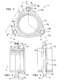
- a wheel bearing assembly 10 is shown in FIG. 1 for supporting a wheel (not shown) in a wheel assembly 11.
- a spindle 12 defines a rotational axis A, and a support member 14 supports the spindle 12.
- Support member 14 may be secured to a portion 100 of the vehicle by fasteners or the like.
- a wheel hub 16 has a flange 17 for securing the wheel thereto and is supported on spindle 12 adjacent support member 14.
- wheel hub 16 is integrally formed with spindle 12.
- Wheel hub 16 and spindle 12 are rotatable about rotational axis A.
- a drive mechanism (not shown) is coupled to spindle 12 for rotationally driving the wheel.
- Bearing assembly 10 is arranged to permit wheel hub 16 and spindle 12 to rotate relative to support member 14, with support member 14 rotatably supporting spindle 12.
- spindle 12 is "rotatably supported” by support member 14 when the spindle is supported so as to permit rotation of the spindle.
- Wheel bearing assembly 10 has first 20 and second 22 bearing members in spaced relation with one another and a plurality of bearings 24, such as ball bearings, retained by a cage 25. Any of a variety of other types of rollable bearing elements (for example, needle roller bearings) may also be used. Bearings 24 are interposed between first 20 and second 22 bearing members to permit relative rotation between the bearing members 20, 22 about rotational axis A. First bearing member 20 is adjacent spindle 12 and second bearing member 22 is adjacent either the wheel hub or the support member, depending on the particular configuration of the wheel assembly 11. In the embodiment shown in FIG. 1, second bearing member 22 is integrally formed with support member 14. Bearing assembly 10 further includes a bearing seal 27 interposed between spindle 12 and support member 14 adjacent bearings 24 to prevent debris from contaminating bearings 24. It is preferred that the diameters of first 20 and second 22 bearing members not change significantly during the assembly process so that bearing seal 27 will fit properly.
- Wheel bearing assembly 10 also has third 52 and fourth 54 bearing members in spaced relation with one another and a plurality of bearings 51, such as ball bearings, retained by a cage 53. Bearings 51 are interposed between third 52 and fourth 54 bearing members to permit relative rotation between the bearing members 52, 54 about rotational axis A.
- third bearing member 52 is integrally formed with spindle 12
- fourth bearing member 54 is integrally formed with support member 14.
- a bearing seal 55 is interposed between spindle 12 and support member 14 adjacent to bearings 51 to prevent debris from contaminating bearings 51. It is preferred that the diameters of third 52 and fourth 54 bearing members not change significantly during the assembly process so that bearing seal 55 will fit properly.
- support member 14 rotatably couples spindle 12 to a portion 100 of a vehicle body.
- spindle 12 is "rotatably coupled" to vehicle portion 100 when the spindle is coupled to the vehicle so as to permit rotation of the spindle with respect to vehicle portion 100.
- Support member 14 includes an annular central sleeve 50 incorporating and/or securing bearing members 20, 22, 52, 54 therein to rotatably support spindle 12 therein.
- a mounting flange 56 extends from sleeve 50, for securing bearing assembly 10 to portion 100 of the vehicle.
- Flange 56 is secured to the vehicle along a mounting face 58 (FIGS. 3-5) of the flange.
- Flange 56 has a concave central portion 60 along which the flange is coupled to sleeve 50.
- flange 56 includes a plurality of equally angularly spaced-apart lobes 64 extending outwardly from central portion 60.
- three lobes are formed spaced apart approximately 120°; however, additional lobes may be formed, depending on the vehicle attachment requirements of a particular application.
- all of the lobes formed need not be equally angularly spaced-apart. Also, as seen in FIG.
- width dimensions lobes 64 taper from a relatively larger width dimension proximate sleeve 50 to a relatively smaller width dimension spaced radially outwardly from the sleeve.
- the lobed configuration reduces the amount of material used in forming the flange.
- a flange without separate lobes may be used.
- the junction between central sleeve 50 and flange central portion 60 has a radius 61 to help relieve any stress concentrations at the junction during flexing of mounting flange 56 with respect to central sleeve 50.
- Flange 56 is substantially concave between lobes 64 (i.e., flange central portion 60 bows inward relative to lobes 64, in a direction indicated by arrow B (FIG.1), generally away from the vehicle.
- one or more through-holes 66 are formed in each of lobes 64 for fasteners used in attaching support member 14 to the vehicle.
- one or more substantially flat bearing surfaces 68a, 68b are formed along each of lobes 64. Bearing surfaces 68a, 68b abut portion 100 of the vehicle and are designed to rest flush against the portion of the vehicle when support member 14 is attached to the vehicle, providing a relatively limited contact area between mounting flange 56 and the vehicle.
- two bearing surfaces 68a and 68b are radially spaced apart to straddle opposite sides of through-hole 66.
- bearing surfaces 68a, 68b are secured to a single, substantially flat surface on the vehicle.
- bearing surfaces 68a, 68b are formed (for example, by machining) so as to be substantially coplanar to help ensure sufficient abutting contact with vehicle portion 100.
- a chamfer 70 may be formed at an end portion of each of lobes 64 to further reduce the contact area between flange 56 and the vehicle.
- mounting flange 56 due to the concave portion of mounting flange 56, a large portion of mounting face 58 is spaced apart from the vehicle. Thus, rather than the entire mounting face 58 being in contact with the vehicle, bearing surfaces 68a, 68b are the only portions of flange 56 in contact with the vehicle when support member 14 is secured to the vehicle. This substantially reduces the contact area between mounting flange 56 and the vehicle, thereby localizing and reducing any impact forces transferred to bearing members 20, 22, 52, 54 through support member 14.
- mounting flange 56 is shaped to permit deflection of the flange in response to side impact loads applied to wheel assembly 11.
- Attachment of bearing members 20, 22, 52, 54 to the vehicle via lobes 64 and the generally concave shape of mounting face 58 radially inwardly of bearing surfaces 68a enable the flange to flex, in the direction indicated by arrow C (FIG.1), in response to a side impact load experienced by wheel assembly 11 and transmitted to bearing members 20, 22, 52, 54.
- This flexibility enables flange 56 to absorb a portion of the side impact load, thereby dampening or attenuating the portion of the load transmitted to the bearings.
- Support member 14 may be fabricated from steel (for example, a high-carbon steel forging) with conventional machining operations used to form bearing surfaces 68a, 68b having the coplanarity required for a given application.
- Wheel bearing assembly 10 is configured to be self-retaining to wheel assembly 11, and may be secured to the spindle using any one of a variety of known methods. Some exemplary methods of retaining bearing assembly 10 to wheel assembly 11 are described in U.S. Patent Nos. 6,574,865, 6,485,187, and 6,622,377, incorporated herein by reference.
- a thickness dimension t of mounting flange 156 may be varied to generally improve the force-deflection characteristics of the flange.
- the thickness t of the mounting flange may be decreased along a direction proceeding from sleeve 50 toward bearing surfaces 68a, effectively providing a taper to flange 56. This configuration helps minimize the weight of flange 56 while optimizing the force-deflection characteristics of the portion of the flange residing radially inwardly of bearing surfaces 68a.
- the thickness of the flange may also be varied as described in instances where a solid (non-lobed) flange configuration is used.
- bearing surfaces 368b, 368b' define a first mounting plane P1 and bearing surfaces 368a, 368a' define a second mounting plane P2 parallel to first mounting plane P1.
- First mounting plane P1 is spaced apart from the second mounting plane P2 in the direction of concavity of the flange. That is, bearing surfaces 368a, 368a' on lobes 364, 364' are slightly recessed a distance d (in the direction of arrow B (FIG.
- the direction of concavity of the flange is defined as the direction in which the concave flange "opens".
- bearing surfaces 368a, 368a' contact the vehicle only when the fasteners have been sufficiently tightened, which causes the portions of the flange residing between bearing surfaces 368a and 368b and the portions of the flange residing between 368a' and 368b' to deflect during tightening of the fasteners, thereby imparting a pre-load to flange 356 (i.e., flange 356 is pre-stressed during attachment to the vehicle).
- This flange pre-load increases the clamping force, or attachment force, with which the flange is secured to the vehicle.
- lobes 264-1 and 264-2 are attached to separate, non-coplanar portions of the vehicle.
- Lobe 264-1 is secured to a surface of the vehicle along a mounting plane P3
- lobe 264-2 is secured to a surface of the vehicle along a mounting plane P4, which is not coplanar with mounting plane P3.
- the local geometries of mounting flange 256 in the regions of lobes 264-1 and 264-2, the coplanarity of bearing surfaces 268-1a, 268-1b, and the coplanarity of bearing surfaces 268-2a, 268-2b along each of the lobes are adjusted so that the bearing surfaces on each lobe may be secured flush with their respective portions of the vehicle.
- the system described herein for rotatably coupling elements is not restricted to the coupling of a wheel spindle to the body of a vehicle. Rather, the system may be utilized in any application in which it is desirable to dampen or attenuate the impact, shock, or vibration forces transmitted to rotating bearing elements.
Landscapes
- Engineering & Computer Science (AREA)
- General Engineering & Computer Science (AREA)
- Mechanical Engineering (AREA)
- Rolling Contact Bearings (AREA)
Applications Claiming Priority (2)
| Application Number | Priority Date | Filing Date | Title |
|---|---|---|---|
| US63754604P | 2004-12-20 | 2004-12-20 | |
| US11/271,606 US7470067B2 (en) | 2004-12-20 | 2005-11-10 | Wheel bearing assembly mount with force attenuation |
Publications (1)
| Publication Number | Publication Date |
|---|---|
| EP1671812A2 true EP1671812A2 (de) | 2006-06-21 |
Family
ID=36001111
Family Applications (1)
| Application Number | Title | Priority Date | Filing Date |
|---|---|---|---|
| EP05077748A Withdrawn EP1671812A2 (de) | 2004-12-20 | 2005-12-01 | Sitz für Radlagervorrichtung mit Kraftdämpfung |
Country Status (2)
| Country | Link |
|---|---|
| US (1) | US7470067B2 (de) |
| EP (1) | EP1671812A2 (de) |
Cited By (3)
| Publication number | Priority date | Publication date | Assignee | Title |
|---|---|---|---|---|
| DE102008061112A1 (de) * | 2008-12-09 | 2010-06-10 | Bosch Mahle Turbo Systems Gmbh & Co. Kg | Abgasturbolader |
| US10174786B2 (en) * | 2014-12-10 | 2019-01-08 | Ntn Corporation | Wheel bearing apparatus and its mounting structure |
| WO2024199564A1 (de) * | 2023-03-28 | 2024-10-03 | Schaeffler Technologies AG & Co. KG | RADLAGEREINHEIT UND ÄUßERES RINGELEMENT |
Families Citing this family (9)
| Publication number | Priority date | Publication date | Assignee | Title |
|---|---|---|---|---|
| EP1647418B1 (de) * | 2004-10-13 | 2012-06-27 | Nsk Ltd. | Nabeneinheit mit Radträger und Lagerring, und Verfahren zur Herstellung der Nabeneinheit |
| JP5242957B2 (ja) * | 2007-07-09 | 2013-07-24 | Ntn株式会社 | 車輪用軸受装置 |
| JP2010151311A (ja) * | 2008-11-28 | 2010-07-08 | Jtekt Corp | 車輪用転がり軸受装置 |
| DE102009009128A1 (de) * | 2009-02-17 | 2010-08-19 | Bosch Mahle Turbo Systems Gmbh & Co. Kg | Lagereinrichtung |
| KR101734232B1 (ko) * | 2016-07-08 | 2017-05-24 | 현대자동차 주식회사 | 센서캡 교환용 툴장치 |
| JP1574957S (de) * | 2016-11-24 | 2017-08-07 | ||
| JP1577824S (de) * | 2016-11-24 | 2020-06-01 | ||
| JP1601194S (de) * | 2017-10-12 | 2018-04-09 | ||
| US10767700B2 (en) * | 2017-11-14 | 2020-09-08 | Aktiebolaget Skf | Flanged inner ring for wheel hub bearings |
Citations (2)
| Publication number | Priority date | Publication date | Assignee | Title |
|---|---|---|---|---|
| US6485187B1 (en) | 2000-10-24 | 2002-11-26 | Delphi Technologies, Inc. | Self-retained wheel bearing assembly |
| US6622377B1 (en) | 2000-10-24 | 2003-09-23 | Delphi Technologies, Inc. | Wheel bearing with separable inner race processing feature |
Family Cites Families (16)
| Publication number | Priority date | Publication date | Assignee | Title |
|---|---|---|---|---|
| US2812987A (en) * | 1956-10-17 | 1957-11-12 | Scott & Fetzer Co | Bearing mounting structures |
| US3372962A (en) * | 1966-02-21 | 1968-03-12 | Gen Precision Systems Inc | Spindle apparatus useful with rotating memory discs |
| US3360998A (en) * | 1966-03-10 | 1968-01-02 | Gen Motors Corp | Flexible chain sprocket support |
| NL164807C (nl) * | 1970-02-05 | 1981-02-16 | Skf Svenska Kullagerfab Ab | Voertuig met aangedreven en niet-aangedreven loop- wielen, voorzien van dezelfde lagereenheid. |
| US4027931A (en) | 1975-10-03 | 1977-06-07 | Carrier Corporation | Flexible damped bearing support |
| CH673052A5 (de) | 1987-01-30 | 1990-01-31 | Bbc Brown Boveri & Cie | |
| EP0544986B1 (de) * | 1991-12-04 | 1996-03-13 | Firma Carl Freudenberg | Lager |
| US5364194A (en) | 1993-01-04 | 1994-11-15 | Ampex Systems Corporation | Axially displaced flexural bearing support |
| DE19630293A1 (de) | 1996-07-26 | 1998-01-29 | Schaeffler Waelzlager Kg | Vorgespanntes Radialwälzlager |
| US5931585A (en) * | 1997-05-21 | 1999-08-03 | Amana Company, L.P. | Bearing mounting structure with reduced dimensional requirements |
| SE517176C2 (sv) | 1997-06-11 | 2002-04-23 | Alfa Laval Ab | Stödanordning för en centrifugalseparator |
| ES2171337B1 (es) * | 1998-11-13 | 2003-06-16 | Fagor S Coop | Olla expres con bloqueo del cierre de la tapa. |
| US6376952B1 (en) | 1999-07-14 | 2002-04-23 | E. I. Du Pont De Nemours And Company | Bearing system for a rotating shaft |
| US6517246B2 (en) | 2000-12-29 | 2003-02-11 | Spx Corporation | Flexible support and method for a steady bearing |
| JP4911333B2 (ja) * | 2001-07-18 | 2012-04-04 | 株式会社ジェイテクト | 車輪用軸受装置における車輪取付け構造 |
| US7832939B2 (en) * | 2001-09-04 | 2010-11-16 | Ntn Corporation | Bearing apparatus for a wheel |
-
2005
- 2005-11-10 US US11/271,606 patent/US7470067B2/en active Active
- 2005-12-01 EP EP05077748A patent/EP1671812A2/de not_active Withdrawn
Patent Citations (3)
| Publication number | Priority date | Publication date | Assignee | Title |
|---|---|---|---|---|
| US6485187B1 (en) | 2000-10-24 | 2002-11-26 | Delphi Technologies, Inc. | Self-retained wheel bearing assembly |
| US6574865B2 (en) | 2000-10-24 | 2003-06-10 | Delphi Technologies, Inc. | Self-retained wheel bearing assembly |
| US6622377B1 (en) | 2000-10-24 | 2003-09-23 | Delphi Technologies, Inc. | Wheel bearing with separable inner race processing feature |
Cited By (3)
| Publication number | Priority date | Publication date | Assignee | Title |
|---|---|---|---|---|
| DE102008061112A1 (de) * | 2008-12-09 | 2010-06-10 | Bosch Mahle Turbo Systems Gmbh & Co. Kg | Abgasturbolader |
| US10174786B2 (en) * | 2014-12-10 | 2019-01-08 | Ntn Corporation | Wheel bearing apparatus and its mounting structure |
| WO2024199564A1 (de) * | 2023-03-28 | 2024-10-03 | Schaeffler Technologies AG & Co. KG | RADLAGEREINHEIT UND ÄUßERES RINGELEMENT |
Also Published As
| Publication number | Publication date |
|---|---|
| US7470067B2 (en) | 2008-12-30 |
| US20060133708A1 (en) | 2006-06-22 |
Similar Documents
| Publication | Publication Date | Title |
|---|---|---|
| EP0849481B1 (de) | Expandierbarer Lagerkäfig | |
| CN100408877C (zh) | 角接触球轴承结构的车轮轴承单元 | |
| US7470067B2 (en) | Wheel bearing assembly mount with force attenuation | |
| EP2602123B1 (de) | Integrierte Nabenlageranordnung für das Rad eines Kraftfahrzeugs | |
| US9759254B2 (en) | Wheel bearing apparatus | |
| TWI833786B (zh) | 滾筒及具備該滾筒之移動車輛用之輪具 | |
| JPH07167138A (ja) | 車輪用複列アンギュラ型玉軸受 | |
| JP2003097588A (ja) | 自動車駆動輪ハブユニット | |
| CN115003925B (zh) | 机动车辆车轮组件 | |
| KR20070113189A (ko) | 차륜 허브 조인트 유닛 | |
| US6883236B2 (en) | Vehicle-use bearing apparatus | |
| JP5401997B2 (ja) | 駆動輪支持用ハブユニット | |
| KR102543652B1 (ko) | 휠베어링 조립체 | |
| JP3887349B2 (ja) | 車輪支持用ハブユニット | |
| CN120712421A (zh) | 车轮用轴承装置 | |
| KR102667606B1 (ko) | 휠베어링 조립체 | |
| JP2002195254A (ja) | 車輪軸受装置 | |
| CN101410258A (zh) | 非对称轮毂组件 | |
| JP2004306681A (ja) | 車輪支持用転がり軸受ユニット | |
| US11453238B2 (en) | Wheel bearing assembly | |
| JP4436386B2 (ja) | 車輪用軸受およびそれを備えた車輪用軸受装置 | |
| JPH11148516A (ja) | 複列転がり軸受 | |
| CA2711804C (en) | Asymmetric hub assembly | |
| JP2022154869A (ja) | 車輪支持装置 | |
| KR102769371B1 (ko) | 개선된 차륜 장착 플랜지 구조를 갖는 휠베어링 |
Legal Events
| Date | Code | Title | Description |
|---|---|---|---|
| PUAI | Public reference made under article 153(3) epc to a published international application that has entered the european phase |
Free format text: ORIGINAL CODE: 0009012 |
|
| AK | Designated contracting states |
Kind code of ref document: A2 Designated state(s): AT BE BG CH CY CZ DE DK EE ES FI FR GB GR HU IE IS IT LI LT LU LV MC NL PL PT RO SE SI SK TR |
|
| AX | Request for extension of the european patent |
Extension state: AL BA HR MK YU |
|
| STAA | Information on the status of an ep patent application or granted ep patent |
Free format text: STATUS: THE APPLICATION IS DEEMED TO BE WITHDRAWN |
|
| 18D | Application deemed to be withdrawn |
Effective date: 20090701 |