EP1671826A2 - Seitenfensterrollo für Kraftfahrzeuge - Google Patents
Seitenfensterrollo für Kraftfahrzeuge Download PDFInfo
- Publication number
- EP1671826A2 EP1671826A2 EP05027414A EP05027414A EP1671826A2 EP 1671826 A2 EP1671826 A2 EP 1671826A2 EP 05027414 A EP05027414 A EP 05027414A EP 05027414 A EP05027414 A EP 05027414A EP 1671826 A2 EP1671826 A2 EP 1671826A2
- Authority
- EP
- European Patent Office
- Prior art keywords
- roller blind
- guide rail
- carriage
- side window
- window
- Prior art date
- Legal status (The legal status is an assumption and is not a legal conclusion. Google has not performed a legal analysis and makes no representation as to the accuracy of the status listed.)
- Granted
Links
- 238000004804 winding Methods 0.000 claims description 5
- 230000006978 adaptation Effects 0.000 description 3
- 230000005540 biological transmission Effects 0.000 description 3
- 235000013405 beer Nutrition 0.000 description 1
- 238000006073 displacement reaction Methods 0.000 description 1
- 238000009434 installation Methods 0.000 description 1
- 238000004519 manufacturing process Methods 0.000 description 1
- 230000002787 reinforcement Effects 0.000 description 1
- 230000000284 resting effect Effects 0.000 description 1
- 238000005096 rolling process Methods 0.000 description 1
Images


Classifications
-
- B—PERFORMING OPERATIONS; TRANSPORTING
- B60—VEHICLES IN GENERAL
- B60J—WINDOWS, WINDSCREENS, NON-FIXED ROOFS, DOORS, OR SIMILAR DEVICES FOR VEHICLES; REMOVABLE EXTERNAL PROTECTIVE COVERINGS SPECIALLY ADAPTED FOR VEHICLES
- B60J1/00—Windows; Windscreens; Accessories therefor
- B60J1/20—Accessories, e.g. wind deflectors, blinds
- B60J1/2011—Blinds; curtains or screens reducing heat or light intensity
- B60J1/2013—Roller blinds
- B60J1/2036—Roller blinds characterised by structural elements
- B60J1/2044—Draw bars, including elements attached to it, e.g. sliding shoes, gripping elements or pull cords
-
- B—PERFORMING OPERATIONS; TRANSPORTING
- B60—VEHICLES IN GENERAL
- B60J—WINDOWS, WINDSCREENS, NON-FIXED ROOFS, DOORS, OR SIMILAR DEVICES FOR VEHICLES; REMOVABLE EXTERNAL PROTECTIVE COVERINGS SPECIALLY ADAPTED FOR VEHICLES
- B60J1/00—Windows; Windscreens; Accessories therefor
- B60J1/20—Accessories, e.g. wind deflectors, blinds
- B60J1/2011—Blinds; curtains or screens reducing heat or light intensity
- B60J1/2013—Roller blinds
- B60J1/2019—Roller blinds powered, e.g. by electric, hydraulic or pneumatic actuators
- B60J1/2027—Roller blinds powered, e.g. by electric, hydraulic or pneumatic actuators with a buckle-proof guided flexible actuating element acting on the draw bar for pushing or push-pulling, e.g. a Bowden cable
-
- B—PERFORMING OPERATIONS; TRANSPORTING
- B60—VEHICLES IN GENERAL
- B60J—WINDOWS, WINDSCREENS, NON-FIXED ROOFS, DOORS, OR SIMILAR DEVICES FOR VEHICLES; REMOVABLE EXTERNAL PROTECTIVE COVERINGS SPECIALLY ADAPTED FOR VEHICLES
- B60J1/00—Windows; Windscreens; Accessories therefor
- B60J1/20—Accessories, e.g. wind deflectors, blinds
- B60J1/2011—Blinds; curtains or screens reducing heat or light intensity
- B60J1/2013—Roller blinds
- B60J1/2036—Roller blinds characterised by structural elements
- B60J1/2052—Guides
-
- B—PERFORMING OPERATIONS; TRANSPORTING
- B60—VEHICLES IN GENERAL
- B60J—WINDOWS, WINDSCREENS, NON-FIXED ROOFS, DOORS, OR SIMILAR DEVICES FOR VEHICLES; REMOVABLE EXTERNAL PROTECTIVE COVERINGS SPECIALLY ADAPTED FOR VEHICLES
- B60J1/00—Windows; Windscreens; Accessories therefor
- B60J1/20—Accessories, e.g. wind deflectors, blinds
- B60J1/2011—Blinds; curtains or screens reducing heat or light intensity
- B60J1/2013—Roller blinds
- B60J1/2066—Arrangement of blinds in vehicles
- B60J1/2086—Arrangement of blinds in vehicles specially adapted for openable windows, e.g. side window
Definitions
- the invention relates to a side window roller blind for motor vehicles according to the preamble of claim 1.
- Such, for example, from DE 100 05 970 A1 known side window roller blind has a roller blind, which completely or largely covers two separated by a window dividing web window areas in the extended state.
- a tension rod is attached, which is guided by means of a carriage along a guide rail.
- the carriage is driven by a drive device, for example a DC electric motor.
- the single guide rail is attached to the front vertical window frame of the front window surface, which is located near the B-pillar of the vehicle.
- the drawbar in the form of a cantilever and a rim reinforcement strip extends over the front window surface.
- the roller blind has a corresponding blank.
- the tension rod which extends along both window surfaces, is supported and guided both along the front vertical window frame part of the front window surface and along the window distribution web by guide means and drive means.
- the object of the invention is to provide a side window blind of the type mentioned, in which with simple Means a stable coverage of the two windows separated by the window dividing web is achieved.
- a single guide rail for guiding the carriage, to which the tension rod is attached is used.
- This guide rail is attached to the window dividing web and the pull rod extends along both window surfaces.
- the roller blind covers both windows completely or at least for the most part.
- the front window surface can practically be covered in its entirety, and the rear window surface, which is trapezoidal or triangular in shape, is largely or almost completely covered.
- the predetermined by the guide rail movement direction of the carriage can run parallel to the window dividing web. Such a direction of movement is preferably used when the window dividing web in side view extends approximately vertically or approximately vertically.
- the predetermined by the guide rail movement direction of the carriage may also extend obliquely to the longitudinal extent of the window dividing web to achieve a carriage movement in the vertical direction or approximately vertical direction in side view of the window.
- the tension rod can be fastened to the carriage by means of at least one attachment means inserted through at least one slot.
- fasteners preferably screw connections are used.
- the at least one slot is located on the tension rod and the fastening means is preferably fastened by screw connection to the carriage.
- manufacturing tolerances can be compensated and an adaptation of the tension rod assembly can be achieved in the course of the upper edges of the two window surfaces in a tight, especially wrinkle-free roller blind guide.
- a tolerance compensation in the order of up to 5 mm, in particular 3 mm can be achieved.
- a slot and an associated fastener or two elongated holes and two associated fastening means are used.
- the slot extends in the longitudinal direction of the tension rod.
- the tension rod can be movably guided along the elongated hole or along the oblong holes during extension and retraction of the roller blind. This achieves a kinematic adaptation to the given geometry of the window surfaces to be covered.
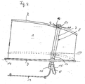
- the embodiments illustrated in the figures have a roller blind 1, which in the extended state, which is shown in FIGS. 1, 3, 5 and 7, substantially both window surfaces 4 and 5, which are separated by a window dividing web 8, cover.
- the upper extendable end of the blind sheet 1 is attached to a pull rod 2.
- the pull rod 2 extends with the roller blind pulled out approximately along the entire upper edges of the window surfaces 4 and 5 on both sides of the window dividing web 8. Since the rear window surface 5 is smaller than the front window surface, the Glasstabaci is at the rear window area about a third or a quarter of total tension rod length.
- the respective partial lengths of the tension rod on both sides of the window dividing web 8 depend on the expansions of the two window surfaces 4, 5 in the vehicle longitudinal direction.
- roller blind cassette 3 which essentially serves as a winding device for the roller blind.
- An essential component is a winding shaft on which the roller blind can be wound up.
- the roller blind can be housed exposed or protected in a cassette housing in the wound state.
- the support of the roller blind cassette 3 and thus the support of the underside of the roller blind 1, in particular in the extended state takes place at one end of the roller blind cassette, in particular at the front end of the roller blind cassette 3 in an attachment point 14.
- a second attachment point is below the window dividing web 8 in a common attachment point 15 for a drive device 6, in particular a DC electric motor provided.
- the pull rod 2 In the rest position, in which the blind sheet 1 is wound up in the roller blind cassette 3, the pull rod 2 is located in a lower dashed line position below the lower edges of the window surfaces 4 and 5.
- the tension rod 2 is attached to a carriage 9.
- the respective carriages 9 and attachment points can be designed differently.
- the illustrated embodiments in common is the arrangement of the guide rail 7 along the window dividing web 8.
- the guide rails 7 are fixed to the window dividing web 8 and are for this purpose with Positive fit in along the respective window dividing webs 8 extending fastening grooves (longitudinal grooves) 19 used.
- the drive device 6 is preferably designed as a DC electric motor, in particular a geared motor.
- the drive torque is transmitted, for example via a pinion 16, which is driven by the electric motor, on a flexible pull / push rod, which may be formed in particular as a brush cable.
- the flexible pull / push rod 12 is guided in a guide channel 17 of the guide rail 7.
- the flexible pull / push rod (brush cable) 12 in a tubular outlet 13 in the door trim of the vehicle door, within which the blind cassette 3 and the drive means 6 are arranged hidden. It is preferably beer to the rear door of the vehicle.
- the addressed components can also be located in a built-in vehicle side boundary of the vehicle interior.
- the guide rails 7 are attached to the window dividing webs 8 in the embodiments.
- the respective guide rail 7 has a fastening strip 20, which can be integrally formed on the guide rail 7.
- the mounting strip 20 is held on both sides in the longitudinal groove 19 which is integrally formed on the window dividing web 8.
- the longitudinal groove 19 can have the fastening strip 20 overlapping legs, so that the guide rail 7 is fastened in all directions to the window-dividing web 8 over its entire length.
- the guide rails 7 have attachment points 21 for attaching the guide rails 7 at their upper ends to the vehicle body.
- fastening points 18 are provided, with which the respective roller blind cassette 3 can be firmly connected to the guide rail 7. Furthermore, the fixed connection of the guide rail 7 takes place together with the respective roller blind cassette 3 in the region of the attachment points 18 with the common attachment point 15, with which the drive device 6 is attached to the vehicle body, for example to the vehicle door.
- the drive device, the guide rail 7, the roller blind cassette and the associated parts, such as roller blind, carriage and pull rod can be formed as a prefabricated unit, which can be arranged in a simple manner on the window dividing web, for example by inserting the fixing strip 20 in the longitudinal groove 19 , The attachment is then in the upper attachment points 21 and the common attachment point 15.
- the front end of the roller blind cassette 3 in the front attachment point 14 are attached to the vehicle body.
- a side window blind with a uniform structure and substantially identical components can be provided.
- the guide channels 17 must be formed in the guide rails 7 accordingly.
- the guide channels 17 extend substantially parallel to the longitudinal extent of the guide rails 7 and the window dividing webs 8.
- the guide channels 17 extend obliquely to the longitudinal extent of the guide shanks 7 and of the window-dividing webs 8. The oblique inclination is such that substantially a parallel guidance to the window surfaces 4 and 5 to be covered and a substantially vertical or approximately vertical direction of movement for the carriage 9 and the tension rod 2 is achieved.
- 6 of the carriage 9 is equipped with a guide rail 7 encompassing slide member 22. Lateral legs of the encompassing slide part 22 engage in lateral guide grooves 23 on the guide rail 7. The lateral guide grooves extend in the longitudinal direction of the guide rail 7.
- the carriage 9 is fixed in all embodiments of the flexible pull / push rod 12, in particular at the upper end of this rod and is together with the longitudinal displacement of the flexible pull / push rod 12 in the guide channel 17th with postponed.
- the attachment of the tension rod 2 takes place in the embodiments 1, 2 and 5, 6 at two attachment points.
- two elongated holes 10 are provided in the pull rod 2, are inserted through the fastening means 11 in the form of fastening screws and are connected by screw connection to the respective slide 9.
- the elongated holes 10 are dimensioned so that, for example, a tolerance compensation in the order of 3 mm or slightly larger (up to 5 mm) is possible. This achieves the possibility of adaptation after installation of the side window blinds in the vehicle to the geometric conditions in the side window area of the respective vehicle.
- the guide carriage is guided in the guide channel 17 of the guide rail 7.
- the carriage extends with a guide pin 24 through a slot 25 in the guide rail 7.
- the slot 25 extends parallel to the guide channel 17 in the guide rail 7. Since in the embodiment of Figs. 3 and 4, the guide channel 17 extends obliquely to the guide rail, runs also Slit 25 obliquely to the longitudinal extent of the guide rail 7.
- the slot 25 extends approximately parallel to the longitudinal extent of the guide rail 7th
- the slot 10 is provided in the pull rod 2, through which the fastening means 11 is inserted through in the form of a fastening screw.
- the fastening means 11 is preferably firmly connected by screw connection with the carriage or the guide pin 24 on the carriage.
- the slot 10 may be sized so that a tolerance compensation in the order of 3 mm and slightly larger (up to 5 mm) is possible, as already explained in the previous embodiments.
- an attachment point between the carriage 9 and the pull rod 2 is provided.
- the carriage may be formed in such a way that it is guided on the outside, as in the embodiments of FIGS. 1, 2 and 5, 6, or as in the embodiment 3, 4 in the guide channel 17 is guided.
- an attachment point and two attachment points can be provided.
- the connection between the tension rod 2 and the carriage 9 is such that the tension rod can move relative to the carriage along the slot 10 when pulling out and rolling up the roller blind 1.
- the longitudinal slot 10 can for this purpose have an extent of the order of 50 mm ( ⁇ 10%).
- guiding the guide channel 17 parallel to the guide rail 7 and the window dividing web 8 can also be an oblique arrangement of the guide channel 17, as in the embodiments of FIGS. 3 to 6 may be provided.
- the guided along the guide channel 17 drive transmission means with which the drive torque of the electric motor is transmitted to the carriage 9, as a flexible pull / push rod 12, with which the carriage 9 is fixedly connected formed.
- a spindle drive which is driven by the electric motor of the drive device 6, may be arranged in the guide channel 17.
- the carriage 9 is then in threaded engagement with the spindle and is moved during the spindle rotation along the guide means 7 when pulling out and winding the blind sheet 1.
- Any torque transmitting means which is adapted to convert the drive torque imparted by the electric motor into a longitudinal movement of the carriage 9 along the guide rail can be used in the invention. In this way it is possible, both with the electric motor by reversing its direction of rotation, both the pull-out and the winding of the blind 1 when covering and re-enabling the two windows 4 and 5 execute.
Landscapes
- Engineering & Computer Science (AREA)
- Mechanical Engineering (AREA)
- Operating, Guiding And Securing Of Roll- Type Closing Members (AREA)
Abstract
Description
- Die Erfindung betrifft ein Seitenfensterrollo für Kraftfahrzeuge nach dem Oberbegriff des Patentanspruches 1.
- Ein derartiges, beispielsweise aus DE 100 05 970 A1 bekanntes Seitenfensterrollo weist eine Rollobahn auf, welche im ausgezogenen Zustand zwei durch einen Fensterteilungssteg voneinander getrennte Fensterflächen ganz oder größtenteils abdeckt. Am ausziehbaren Ende der Rollobahn ist ein Zugstab befestigt, der mit Hilfe eines Schlittens entlang einer Führungsschiene geführt wird. Der Schlitten wird von einer Antriebseinrichtung, beispielsweise einem elektrischen Gleichstrommotor angetrieben. Die einzige Führungsschiene ist am vorderen vertikalen Fensterrahmen der vorderen Fensterfläche, welche sich in der Nähe der B-Säule des Fahrzeugs befindet, befestigt. Der Zugstab in Form eines Auslegers und einer Randverstärkungsleiste erstreckt sich über die vordere Fensterfläche. Zum Abdecken der hinteren Fensterfläche, welche als Dreiecksfenster ausgebildet ist, besitzt die Rollobahn einen entsprechenden Zuschnitt.
- Bei einem weiteren aus der DE 100 05 970 A1 bekannten Ausführungsbeispiel wird der Zugstab, welcher sich entlang beider Fensterflächen erstreckt, sowohl entlang dem vorderen vertikalen Fensterrahmenteil der vorderen Fensterfläche als auch entlang dem Fensterteilungssteg durch Führungsmittel und Antriebsmittel gestützt und geführt.
- Aufgabe der Erfindung ist es, ein Seitenfensterrollo der eingangs genannten Art zu schaffen, bei welchem mit einfachen Mitteln eine stabile Abdeckung der beiden durch den Fensterteilungssteg voneinander getrennten Fensterflächen erzielt wird.
- Diese Aufgabe wird erfindungsgemäß durch die kennzeichnenden Merkmale des Patentanspruches 1 gelöst.
- Bei der Erfindung kommt eine einzige Führungsschiene zur Führung des Schlittens, an welchem der Zugstab befestigt ist, zur Anwendung. Diese Führungsschiene ist am Fensterteilungssteg befestigt und der Zugstab erstreckt sich entlang beider Fensterflächen. Im ausgezogenen Zustand wird hierdurch eine zwischen den Enden des Zugstabes liegende Abstützung des Zugstabes und eine Halterung der Rollobahn an der gesamten Ausdehnung ihres oberen ausziehbaren Endes erreicht. Die Rollobahn deckt beide Fensterflächen ganz oder zumindest größtenteils ab. Die vordere Fensterfläche kann praktisch,insgesamt abdeckt werden und die hintere Fensterfläche, welche trapez- oder dreieckförmig ausgebildet ist, wird größtenteils oder annährend ganz abgedeckt.
- Die von der Führungsschiene vorgegebene Bewegungsrichtung des Schlittens kann parallel zum Fensterteilungssteg verlaufen. Eine solche Bewegungsrichtung kommt bevorzugt dann zur Anwendung, wenn der Fensterteilungssteg in Seitenansicht in etwa vertikal oder annährend vertikal verläuft.
- Die von der Führungsschiene vorgegebene Bewegungsrichtung des Schlittens kann jedoch auch schräg zur Längsausdehnung des Fensterteilungsstegs verlaufen, um eine Schlittenbewegung in vertikaler Richtung oder annährend vertikaler Richtung in Seitenansicht des Fensters zu erreichen.
- Der Zugstab kann mittels wenigstens eines durch wenigstens ein Langloch gesteckten Befestigungsmittels am Schlitten befestigt sein. Als Befestigungsmittel kommen bevorzugt Schraubenverbindungen zum Einsatz. Vorzugsweise befindet sich das wenigstens eine Langloch am Zugstab und das Befestigungsmittel wird vorzugsweise durch Schraubenverbindung am Schlitten befestigt. Hierdurch können Fertigungstoleranzen ausgeglichen und eine Anpassung der Zugstabanordnung an den Verlauf der Oberkanten der beiden Fensterflächen bei straffer, insbesondere faltenfreier Rollobahnführung erreicht werden. Beispielsweise lässt sich ein Toleranzausgleich in der Größenordnung bis zu 5 mm, insbesondere 3 mm, erreichen. Hierzu können je nach Anzahl der Befestigungsstellen zwischen dem Schlitten und dem Zugstab entsprechende Langlöcher und Befestigungsmittel vorgesehen sein. Bevorzugt wird ein Langloch und ein zugehöriges Befestigungsmittel oder werden zwei Langlöcher und zwei zugehörige Befestigungsmittel zum Einsatz gebracht.
- In bevorzugter Weise erstreckt sich das Langloch in Längsrichtung des Zugstabes.
- Bei einer weiteren bevorzugten Ausführungsform kann der Zugstab entlang dem Langloch bzw. entlang den Langlöchern beim Ausziehen und Einziehen der Rollobahn beweglich geführt werden. Man erreicht hierdurch eine kinematische Anpassung an die vorgegebene Geometrie der abzudeckenden Fensterflächen.
- Anhand der Figuren wird an Ausführungsbeispielen die Erfindung noch näher erläutert.
- Es zeigt
- Fig. 1
- in Seitenansicht ein erstes Ausführungsbeispiel;
- Fig. 2
- eine Ausführungsform der Führungsschiene des Schlittens und des Zugstabes, insbesondere der Zugstabbefestigung am Schlitten beim Ausführungsbeispiel der Fig. 1;
- Fig. 3
- ein zweites Ausführungsbeispiel in Seitenansicht;
- Fig. 4
- eine Ausführungsform für die Führungsschiene, den Schlitten und die Zugstabbefestigung am Schlitten beim Ausführungsbeispiel der Fig. 3;
- Fig. 5
- in Seitenansicht ein drittes Ausführungsbeispiel;
- Fig. 6
- eine Ausführungsform für die Führungsschiene, den Schlitten und die Zugstabbefestigung am Schlitten beim Ausführungsbeispiel der Fig. 5; und
- Fig. 7
- ein viertes Ausführungsbeispiel in Seitenansicht.
- Die in den Figuren dargestellten Ausführungsbeispiele besitzen eine Rollobahn 1, welche im ausgezogenen Zustand, der in den Fig. 1, 3, 5 und 7 dargestellt ist, im wesentlichen beide Fensterflächen 4 und 5, die durch einen Fensterteilungssteg 8 voneinander getrennt sind, abdecken. Das obere ausziehbare Ende der Rollobahn 1 ist an einem Zugstab 2 befestigt. Der Zugstab 2 erstreckt sich bei ausgezogener Rollobahn etwa entlang der gesamten Oberkanten der Fensterflächen 4 und 5 zu beiden Seiten des Fensterteilungssteges 8. Da die hintere Fensterfläche 5 kleiner ist als die vordere Fensterfläche beträgt die Zugstablänge bei der hinteren Fensterfläche etwa ein Drittel oder ein Viertel der gesamten Zugstablänge. Die jeweiligen Teillängen des Zugstabes zu beiden Seiten des Fensterteilungssteges 8 hängen von den Ausdehnungen der beiden Fensterflächen 4, 5 in Fahrzeuglängsrichtung ab. Hierdurch wird eine stabile Abstützung der Rollobahn 1 im wesentlichen über ihre gesamte Ausdehnung in Längsausdehnung des Fahrzeugs am ausziehbaren Rollobahnende erreicht. An der Unterseite der Rollobahn 1 befindet sich eine Rollokassette 3, die im wesentlichen als Aufwickelvorrichtung für die Rollobahn dient. Wesentlicher Bestandteil ist eine Wickelwelle, auf welche die Rollobahn aufgewickelt werden kann. Die Rollobahn kann im aufgewickelten Zustand freiliegend oder geschützt in einem Kassettengehäuse untergebracht sein.
- Die Abstützung der Rollokassette 3 und damit die Abstützung der Unterseite der Rollobahn 1, insbesondere im ausgezogenen Zustand erfolgt an einem Ende der Rollokassette, insbesondere am vorderen Ende der Rollokassette 3 in einer Befestigungsstelle 14. Eine zweite Befestigungsstelle ist unterhalb des Fensterteilungssteg 8 in einer gemeinsamen Befestigungsstelle 15 für eine Antriebseinrichtung 6, insbesondere einen elektrischen Gleichstrommotor vorgesehen.
- In der Ruheposition, bei welcher die Rollobahn 1 in der Rollokassette 3 aufgewickelt ist, befindet sich der Zugstab 2 in einer unteren strichliert dargestellten Position unterhalb der unteren Kanten der Fensterflächen 4 und 5.
- Der Zugstab 2 ist an einem Schlitten 9 befestigt. Wie im einzelnen noch ausgeführt wird, können die jeweiligen Schlitten 9 und Befestigungsstellen unterschiedlich ausgebildet sein. Den dargestellten Ausführungsbeispielen gemeinsam ist die Anordnung der Führungsschiene 7 entlang dem Fensterteilungssteg 8. Vorzugsweise sind die Führungsschienen 7 am Fensterteilungssteg 8 befestigt und sind hierzu mit Formschluss in entlang der jeweiligen Fensterteilungsstege 8 verlaufenden Befestigungsnuten (Längsnuten) 19 eingesetzt.
- Die Antriebseinrichtung 6 ist vorzugsweise als elektrischer Gleichstrommotor, insbesondere Getriebemotor ausgebildet. Das Antriebsmoment wird beispielsweise über ein Ritzel 16, welches vom Elektromotor angetrieben wird, auf eine flexible Zug-/Druckstange, die insbesondere als Bürstenkabel ausgebildet sein kann, übertragen. Auf diese Weise wird die Drehbewegung des Elektromotors in eine translatorische Bewegung umgesetzt. Die flexible Zug-/Druckstange 12 wird in einem Führungskanal 17 der Führungsschiene 7 geführt. Im Ruhezustand oder teilweise ausgezogenen Zustand der Rollobahn 1 befindet sich die flexible Zug-/Druckstange (Bürstenkabel) 12 in einem rohrförmigen Auslauf 13 in der Türverkleidung der Fahrzeugtür, innerhalb welcher auch die Rollokassette 3 und die Antriebseinrichtung 6 verdeckt angeordnet sind. Es handelt sich bier vorzugsweise um die Fondtür des Fahrzeugs. Die angesprochenen Bauteile können sich jedoch auch in einer fest im Fahrzeug eingebauten Seitenbegrenzung des Fahrzeuginnenraums befinden.
- Wie schon erläutert, sind die Führungsschienen 7 an den Fensterteilungsstegen 8 bei den Ausführungsbeispielen befestigt. Hierzu besitzt die jeweilige Führungsschiene 7 eine Befestigungsleiste 20, welche einstückig an die Führungsschiene 7 angeformt sein kann. Die Befestigungsleiste 20 wird beidseitig in der Längsnut 19, die an den Fensterteilungssteg 8 angeformt ist, festgehalten. Die Längsnut 19 kann hierzu die Befestigungsleiste 20 übergreifende Schenkel aufweisen, so dass die Führungsschiene 7 nach allen Richtungen hin über ihre gesamte Länge an den Fensterteilungssteg 8 befestigt ist.
- Am oberen Ende besitzen die Führungsschienen 7 Befestigungspunkte 21 zum Befestigen der Führungsschienen 7 an ihren oberen Enden am Fahrzeugaufbau. An den unteren Enden der Führungsschienen 7 sind Befestigungsstellen 18 vorgesehen, mit denen die jeweilige Rollokassette 3 mit der Führungsschiene 7 fest verbunden werden kann. Ferner erfolgt die feste Verbindung der Führungsschiene 7 zusammen mit der jeweiligen Rollokassette 3 im Bereich der Befestigungsstellen 18 mit der gemeinsamen Befestigungsstelle 15, mit welcher auch die Antriebseinrichtung 6 am Fahrzeugaufbau, beispielsweise an der Fahrzeugtür befestigt wird.
- Hierdurch können die Antriebseinrichtung, die Führungsschiene 7, die Rollokassette und die zugeordneten Teile, wie Rollobahn, Schlitten und Zugstab, als vorgefertigte Baueinheit ausgebildet werden, die in einfacher Weise an dem Fensterteilungssteg, beispielsweise durch Einschieben der Befestigungsleiste 20 in die Längsnut 19 angeordnet werden kann. Die Befestigung erfolgt dann in den oberen Befestigungspunkten 21 und der gemeinsamen Befestigungsstelle 15. Zusätzlich kann das vordere Ende der Rollokassette 3 in der vorderen Befestigungsstelle 14 am Fahrzeugaufbau befestigt werden.
- Außerdem kann für unterschiedliche Bauformen und geometrische Ausgestaltungen der Fensterflächen 4 und 5 ein Seitenfensterrollo mit einheitlichem Aufbau und im wesentlichen identischen Bauelementen vorgesehen werden. Um unterschiedliche Neigungen der Fensterteilungsstege 8 für eine im wesentlichen vertikale oder eine angenäherte vertikale Bewegungsrichtung des Schlittens 9 und des Zugstabes 2 auszugleichen, müssen lediglich die Führungskanäle 17 in den Führungsschienen 7 entsprechend eingeformt werden.
- Bei den Ausführungsbeispielen der Fig. 1, 2 und 7 verlaufen die Führungskanäle 17 im wesentlichen parallel zu der Längserstreckung der Führungsschienen 7 bzw. der Fensterteilungsstege 8. Bei den Ausführungsbeispielen der Fig. 3 bis 6 verlaufen die Führungskanäle 17 schräg zur Längsausdehnung der Führungsschiänen 7 bzw. der Fensterteilungsstege 8. Die schräge Neigung ist derart, dass im wesentlichen eine Parallelführung zu den abzudeckenden Fensterflächen 4 und 5 sowie eine im wesentlichen vertikale oder annährend vertikale Bewegungsrichtung für den Schlitten 9 und den Zugstab 2 erreicht wird.
- Bei den Ausführungsbeispielen der Fig. 1, 2 und 5, 6 ist der Schlitten 9 mit einem die Führungsschiene 7 umgreifenden Schlittenteil 22 ausgestattet. Seitliche Schenkel des umgreifenden Schlittenteils 22 greifen in seitliche Führungsnuten 23 an der Führungsschiene 7 ein. Die seitlichen Führungsnuten erstrecken sich in Längsrichtung der Führungsschiene 7. Der Schlitten 9 ist bei allen Ausführungsbeispielen an der flexiblen Zug-/Druckstange 12, insbesondere am oberen Ende dieser Stange befestigt und wird zusammen mit der Längsverschiebung der flexiblen Zug-/Druckstange 12 im Führungskanal 17 mit verschoben.
- Die Befestigung des Zugstabes 2 erfolgt bei den Ausführungsformen 1, 2 und 5, 6 an zwei Befestigungsstellen. Hierzu sind im Zugstab 2 zwei Langlöcher 10 vorgesehen, durch die Befestigungsmittel 11 in Form von Befestigungsschrauben hindurchgesteckt sind und durch Schraubenverbindung mit den jeweiligen Schlitten 9 verbunden sind. Die Langlöcher 10 sind so bemessen, dass beispielsweise ein Toleranzausgleich in der Größenordnung von 3 mm oder geringfügig größer (bis zu 5 mm) möglich ist. Man erreicht hierdurch nach dem Einbau des Seitenfensterrollos im Fahrzeug die Möglichkeit der Anpassung an die geometrischen Gegebenheiten im Seitenfensterbereich des jeweiligen Fahrzeugs.
- Beim Ausführungsbeispiel der Fig. 3 und 4 wird der Führungsschlitten im Führungskanal 17 der Führungsschiene 7 geführt. Der Schlitten ragt mit einem Führungszapfen 24 durch einen Schlitz 25 in der Führungsschiene 7. Der Schlitz 25 erstreckt sich parallel zum Führungskanal 17 in der Führungsschiene 7. Da beim Ausführungsbeispiel der Fig. 3 und 4 der Führungskanal 17 schräg zur Führungsschiene verläuft, verläuft auch der Schlitz 25 schräg zur Längsausdehnung der Führungsschiene 7. Bei einer Ausgestaltung des Ausführungsbeispiels der Fig. 3 und 4 derart, dass der Führungskanal 17 im wesentlichen parallel zur Längsausdehnung der Führungsschiene 7 sich erstreckt, erstreckt sich natürlich auch der Schlitz 25 etwa parallel zur Längsausdehnung der Führungsschiene 7.
- Die Befestigung des Zugstabes 2 erfolgt an einer Befestigungsstelle. Hierzu ist im Zugstab 2 das Langloch 10 vorgesehen, durch welches das Befestigungsmittel 11 in Form einer Befestigungsschraube hindurchgesteckt wird. Das Befestigungsmittel 11 wird vorzugsweise durch Schraubverbindung mit dem Schlitten bzw. dem Führungszapfen 24 am Schlitten fest verbunden. Das Langloch 10 kann so bemessen sein, dass ein Toleranzausgleich in der Größenordnung von 3 mm und geringfügig größer (bis zu 5 mm) möglich ist, wie bei den vorherigen Ausführungsbeispielen schon erläutert wurde.
- Beim Ausführungsbeispiel der Fig. 7 ist eine Befestigungsstelle zwischen dem Schlitten 9 und dem Zugstab 2 vorgesehen. Der Schlitten kann in der Weise ausgebildet sein, dass er an der Außenseite, wie bei den Ausführungsbeispielen der Fig. 1, 2 und 5, 6 geführt wird, oder wie beim Ausführungsbeispiel der Fig. 3, 4 im Führungskanal 17 geführt wird. Anstelle der einen Befestigungsstelle können auch zwei Befestigungsstellen vorgesehen sein. Beim Ausführungsbeispiel der Fig. 7 ist die Verbindung zwischen dem Zugstab 2 und dem Schlitten 9 derart, dass sich der Zugstab gegenüber dem Schlitten entlang dem Langloch 10 beim Ausziehen und Aufrollen der Rollobahn 1 bewegen kann. Hierdurch wird ein kinematischer Ausgleich zwischen den einzelnen Bauteilen erreicht. Der Längsschlitz 10 kann hierzu eine Ausdehnung von größenordnungsmäßig 50 mm (± 10 %) aufweisen. Anstelle der Führung des Führungskanals 17 parallel zur Führungsschiene 7 und zum Fensterteilungssteg 8 kann auch eine schräge Anordnung des Führungskanals 17, wie bei den Ausführungsbeispielen der Fig. 3 bis 6 vorgesehen sein.
- Bei den beschriebenen Ausführungsbeispielen ist das entlang dem Führungskanal 17 geführte Antriebsübertragungsmittel, mit welchem das Antriebsmoment des Elektromotors auf den Schlitten 9 übertragen wird, als flexible Zug-/Druckstange 12, mit welcher der Schlitten 9 fest verbunden ist, ausgebildet. Anstelle dieses Drehmomentübertragungsmittels kann auch ein Spindeltrieb, welcher vom Elektromotor der Antriebseinrichtung 6 angetrieben wird, im Führungskanal 17 angeordnet sein. Der Schlitten 9 steht dann in Gewindeeingriff mit der Spindel und wird bei der Spindeldrehung entlang der Führungseinrichtung 7 beim Ausziehen und Aufwickeln der Rollobahn 1 bewegt. Jedes Drehmomentübertragungsmittel, welches geeignet ist, das vom Elektromotor vermittelte Antriebsdrehmoment in eine Längsbewegung des Schlittens 9 entlang der Führungsschiene zu wandeln, kann bei der Erfindung zum Einsatz kommen. Auf diese Weise ist es möglich, allein mit dem Elektromotor durch Umkehrung seiner Drehrichtung sowohl die Ausziehbewegung als auch das Aufwickeln der Rollobahn 1 beim Abdecken und Wiederfreigeben der beiden Fensterflächen 4 und 5 auszuführen.
-
- 1
- Rollobahn
- 2
- Zugstab
- 3
- Rollokassette
- 4,5
- Fensterflächen
- 6
- Antriebseinrichtung
- 7
- Führungsschiene
- 8
- Fensterteilungssteg
- 9
- Schlitten
- 10
- Langloch
- 11
- Befestigungsmittel
- 12
- Antriebsübertragungsmittel (flexible Zug-/Druckstangenbürstenkabel)
- 13
- Auslauf
- 14
- vordere Befestigungsstelle der Rollokassette
- 15
- gemeinsame Befestigungsstelle
- 16
- Ritzel
- 17
- Führungskanal
- 18
- Befestigungsstellen
- 19
- Längsnut
- 20
- Befestigungsleiste an der Führungsschiene
- 21
- obere Befestigungsstelle
- 22
- umgreifendes Schlittenteil
- 23
- seitliche Führungsnuten
- 24
- Führungszapfen
- 25
- Schlitz
Claims (15)
- Seitenfensterrollo für Kraftfahrzeuge mit einer Rollobahn (1), welche im ausgezogenen Zustand (2) durch einen Fensterteilungssteg (8) voneinander getrennte Fensterflächen (4, 5) ganz oder größtenteils abdeckt, einem Zugstab (2), welcher am ausziehbaren Ende der Rollobahn (1) befestigt ist, einer Rollokassette (3) zum Aufwickeln der Rollobahn (1), eine Antriebseinrichtung (6) für die Rollobahn (1), einer einzigen Führungsschiene (7) und einem entlang der Führungsschiene (7) geführten und von der Antriebseinrichtung (6) angetriebenen Schlitten (9), an welchem der Zugstab (2) befestigt ist,
dadurch gekennzeichnet, dass die einzige Führungsschiene (7) am Fensterteilungssteg (8) befestigt ist und der Zugstab (2) sich auf beiden Seiten des Fensterteilungsstegs (8) entlang beider Fensterflächen (4, 5) erstreckt. - Seitenfensterrollo nach Anspruch 1,
dadurch gekennzeichnet, dass die von der Führungsschiene (7) vorgegebene Bewegungsrichtung des Schlittens (9) parallel zum Fensterteilungssteg (8) verläuft. - Seitenfensterrollo nach Anspruch 1 oder 2,
dadurch gekennzeichnet, dass die von der Führungsschiene (7) vorgegebene Bewegungsrichtung des Schlittens (9) schräg zur Längsausdehnung des Fensterteilungsstegs (8) in vertikaler Richtung oder angenähert zur vertikalen Richtung verläuft. - Seitenfensterrollo nach einem der Ansprüche 1 bis 3,
dadurch gekennzeichnet, dass der Zugstab (2) mittels wenigstens eines durch wenigstens ein Langloch (10) gesteckten Befestigungsmittels (11) am Schlitten (9) befestigt ist. - Seitenfensterrollo nach Anspruch 4,
dadurch gekennzeichnet, dass das Langloch (10) am Zugstab (2) vorgesehen ist und das Befestigungsmittel (11) am Schlitten (9) befestigt ist. - Seitenfensterrollo nach einem der Ansprüche 1 bis 5,
dadurch gekennzeichnet, dass das Langloch (10) sich in Längsrichtung des Zugstabes (2) erstreckt. - Seitenfensterrollo nach einem der Ansprüche 1 bis 6,
dadurch gekennzeichnet, dass der Zugstab (2) entlang dem wenigstens einen Langloch (10) gegenüber dem Schlitten (9) beweglich geführt ist. - Seitenfensterrollo nach einem der Ansprüche 1 bis 7,
dadurch gekennzeichnet, dass die Rollokassette (3) mit dem unteren Ende der Führungsschiene (7) fest verbunden ist. - Seitenfensterrollo nach einem der Ansprüche 1 bis 8,
dadurch gekennzeichnet, dass die Führungsschiene (7) an ihrem oberen Ende und an ihrem unteren Ende über Befestigungsstellen (19, 21) am Fahrzeugaufbau befestigt ist. - Seitenfensterrollo nach einem der Ansprüche 1 bis 9,
dadurch gekennzeichnet, dass das untere Ende der Führungsschiene (7), die Rollokassette (3) und die Antriebseinrichtung (6) eine gemeinsame Befestigungsstelle (15) am Fahrzeugaufbau aufweisen. - Seitenfensterrollo nach einem der Ansprüche 1 bis 10, dadurch gekennzeichnet, dass im Innern der Führungsschiene (7) ein Führungskanal (17) vorgesehen ist, entlang welchem das von der Antriebseinrichtung (6) erzeugte Antriebsmoment auf den Schlitten (9) und den Zugstab (2) übertragen wird.
- Seitenfensterrollo nach einem der Ansprüche 1 bis 11,
dadurch gekennzeichnet, dass der Schlitten (9) außen an der Führungsschiene (7) geführt ist. - Seitenfensterrollo nach einem der Ansprüche 1 bis 12,
dadurch gekennzeichnet, dass der Schlitten (9) im Führungskanal (17) der Führungsschiene (7) geführt ist. - Seitenfensterrollo nach einem der Ansprüche 1 bis 13,
dadurch gekennzeichnet, dass die Führungsschiene, die Rollobahn (1) mit Zugstab (2) und die Rollokassette (3) als vormontierte Baueinheit vorgesehen sind. - Seitenfensterrollo nach Anspruch 14,
dadurch gekennzeichnet, dass zur vormontierten Baueinheit ferner die Antriebseinrichtung (6) gehört.
Applications Claiming Priority (1)
| Application Number | Priority Date | Filing Date | Title |
|---|---|---|---|
| DE102004060208A DE102004060208A1 (de) | 2004-12-14 | 2004-12-14 | Seitenfensterrollo für Kraftfahrzeuge |
Publications (3)
| Publication Number | Publication Date |
|---|---|
| EP1671826A2 true EP1671826A2 (de) | 2006-06-21 |
| EP1671826A3 EP1671826A3 (de) | 2007-11-14 |
| EP1671826B1 EP1671826B1 (de) | 2009-12-09 |
Family
ID=35985173
Family Applications (1)
| Application Number | Title | Priority Date | Filing Date |
|---|---|---|---|
| EP05027414A Expired - Lifetime EP1671826B1 (de) | 2004-12-14 | 2005-12-14 | Seitenfensterrollo für Kraftfahrzeuge |
Country Status (3)
| Country | Link |
|---|---|
| EP (1) | EP1671826B1 (de) |
| AT (1) | ATE451264T1 (de) |
| DE (2) | DE102004060208A1 (de) |
Cited By (5)
| Publication number | Priority date | Publication date | Assignee | Title |
|---|---|---|---|---|
| EP1882604A1 (de) * | 2006-07-28 | 2008-01-30 | Wagon Sas | Abdeckungsvorrichtung mit Halteelement und entsprechendes Fahrzeug |
| DE102007011272A1 (de) * | 2007-03-08 | 2008-02-07 | Audi Ag | Sonnenschutzsystem für Kraftfahrzeugfenster |
| FR2910846A1 (fr) * | 2006-12-29 | 2008-07-04 | Wagon Sas | Dispositif d'occultation guide sur un unique element de structure central, portiere et vehicule correspondants |
| JP2015009807A (ja) * | 2013-06-28 | 2015-01-19 | ベーオーエス ゲゼルシャフト ミット ベシュレンクテル ハフツング ウント コンパニー コマンディトゲゼルシャフト | 自動車車室のための保護装置 |
| CN110761697A (zh) * | 2018-07-26 | 2020-02-07 | 昆山皇田汽车配件工业有限公司 | 侧窗卷帘装置 |
Families Citing this family (3)
| Publication number | Priority date | Publication date | Assignee | Title |
|---|---|---|---|---|
| DE102006017883B4 (de) * | 2006-04-13 | 2014-11-06 | Fkt Gmbh | Heckfensterrollo |
| DE102007027158B4 (de) | 2007-06-13 | 2010-06-24 | Lisa Dräxlmaier GmbH | Seitenfensterrollo für Kraftfahrzeuge |
| DE102017212592B4 (de) * | 2017-07-21 | 2019-05-23 | Bos Gmbh & Co. Kg | Schutzvorrichtung für einen Fahrzeuginnenraum |
Citations (1)
| Publication number | Priority date | Publication date | Assignee | Title |
|---|---|---|---|---|
| DE10005970A1 (de) | 2000-02-09 | 2001-08-23 | Bos Gmbh | Seitenfensterrollo |
Family Cites Families (2)
| Publication number | Priority date | Publication date | Assignee | Title |
|---|---|---|---|---|
| DE3822378C2 (de) * | 1988-07-01 | 1994-10-27 | Bayerische Motoren Werke Ag | Fensterrollo für ein Kraftfahrzeug |
| DE10216186A1 (de) * | 2002-04-04 | 2003-10-16 | Brose Fahrzeugteile | Sonnenschutzrollo für ein Fahrzeugfenster |
-
2004
- 2004-12-14 DE DE102004060208A patent/DE102004060208A1/de not_active Withdrawn
-
2005
- 2005-12-14 DE DE502005008668T patent/DE502005008668D1/de not_active Expired - Lifetime
- 2005-12-14 AT AT05027414T patent/ATE451264T1/de not_active IP Right Cessation
- 2005-12-14 EP EP05027414A patent/EP1671826B1/de not_active Expired - Lifetime
Patent Citations (1)
| Publication number | Priority date | Publication date | Assignee | Title |
|---|---|---|---|---|
| DE10005970A1 (de) | 2000-02-09 | 2001-08-23 | Bos Gmbh | Seitenfensterrollo |
Cited By (7)
| Publication number | Priority date | Publication date | Assignee | Title |
|---|---|---|---|---|
| EP1882604A1 (de) * | 2006-07-28 | 2008-01-30 | Wagon Sas | Abdeckungsvorrichtung mit Halteelement und entsprechendes Fahrzeug |
| FR2904265A1 (fr) * | 2006-07-28 | 2008-02-01 | Wagon Sas | Dispositif d'occultation a element de maitien, et vehicule correspondant |
| FR2910846A1 (fr) * | 2006-12-29 | 2008-07-04 | Wagon Sas | Dispositif d'occultation guide sur un unique element de structure central, portiere et vehicule correspondants |
| WO2008083924A1 (fr) * | 2006-12-29 | 2008-07-17 | Wagon Sas | Dispositif d'occultation guide sur un unique element de structure central, portiere et vehicule correspondants |
| DE102007011272A1 (de) * | 2007-03-08 | 2008-02-07 | Audi Ag | Sonnenschutzsystem für Kraftfahrzeugfenster |
| JP2015009807A (ja) * | 2013-06-28 | 2015-01-19 | ベーオーエス ゲゼルシャフト ミット ベシュレンクテル ハフツング ウント コンパニー コマンディトゲゼルシャフト | 自動車車室のための保護装置 |
| CN110761697A (zh) * | 2018-07-26 | 2020-02-07 | 昆山皇田汽车配件工业有限公司 | 侧窗卷帘装置 |
Also Published As
| Publication number | Publication date |
|---|---|
| DE502005008668D1 (de) | 2010-01-21 |
| ATE451264T1 (de) | 2009-12-15 |
| DE102004060208A1 (de) | 2006-06-22 |
| EP1671826B1 (de) | 2009-12-09 |
| EP1671826A3 (de) | 2007-11-14 |
Similar Documents
| Publication | Publication Date | Title |
|---|---|---|
| EP1645448B1 (de) | Fensterrollo für ein Fahrzeugfenster | |
| EP1215063B1 (de) | Fensterrollo mit vereinfachter Montage | |
| DE10362017B4 (de) | Aus Kunststoff gespritzte Führungsschiene und ein Fensterrollo für Kraftfahrzeuge | |
| DE102007012281A1 (de) | Automatisch betätigbares Seitenfensterrollo | |
| EP2062780B1 (de) | Rollosystem | |
| WO2006034690A1 (de) | Rolloanordnung für ein kraftfahrzeug | |
| EP1872989B1 (de) | Fensterrollo für ein Fahrzeugfenster | |
| DE202004014652U1 (de) | Fahrzeugtür mit einem Fensterheber | |
| DE102004020335A1 (de) | Rollosystem für ein Fahrzeugdach | |
| EP1671826B1 (de) | Seitenfensterrollo für Kraftfahrzeuge | |
| EP1724137B1 (de) | Fensterrollo mit längsverstellbarer Wickelwelle | |
| EP1964700B1 (de) | Fahrzeugfensterrollo | |
| DE102017218895B4 (de) | Schutzvorrichtung für einen Innenraum eines Kraftfahrzeugs | |
| EP4037931B1 (de) | Längseinsteller für einen fahrzeugsitz und fahrzeugsitz | |
| EP0706603B1 (de) | Seilzug-fensterheber | |
| DE102008053824B4 (de) | Seiltrommel für eine Verstellvorrichtung und Baugruppe einer Verstellvorrichtung | |
| DE4422489A1 (de) | Fensterheber für ein Kraftfahrzeug | |
| EP2019759A2 (de) | Rollo für fensterscheiben von kraftfahrzeugen | |
| EP1849635B1 (de) | Fensterrollo, welches an der Innenseite eines Kraftfahrzeugfensters anzuordnen ist | |
| WO2009033981A1 (de) | Verstelleinrichtung für eine abdeckvorrichtung in einem kraftfahrzeug | |
| DE29914588U1 (de) | Vorrichtung zum Bewegen einer Gardine | |
| EP1661743B1 (de) | Fensterrollo für ein Fahrzeugfenster | |
| DE102009036780B4 (de) | Führungseinrichtung für eine seilzugbetätigte Verstellvorrichtung | |
| EP1738942A2 (de) | Fensterrollo für Kraftfahrzeuge mit formschlüssigem Anschlag auf dem Betätigungsglied | |
| DE10318153A1 (de) | Längseinsteller für einen Fahrzeugsitz |
Legal Events
| Date | Code | Title | Description |
|---|---|---|---|
| PUAI | Public reference made under article 153(3) epc to a published international application that has entered the european phase |
Free format text: ORIGINAL CODE: 0009012 |
|
| AK | Designated contracting states |
Kind code of ref document: A2 Designated state(s): AT BE BG CH CY CZ DE DK EE ES FI FR GB GR HU IE IS IT LI LT LU LV MC NL PL PT RO SE SI SK TR |
|
| AX | Request for extension of the european patent |
Extension state: AL BA HR MK YU |
|
| PUAL | Search report despatched |
Free format text: ORIGINAL CODE: 0009013 |
|
| AK | Designated contracting states |
Kind code of ref document: A3 Designated state(s): AT BE BG CH CY CZ DE DK EE ES FI FR GB GR HU IE IS IT LI LT LU LV MC NL PL PT RO SE SI SK TR |
|
| AX | Request for extension of the european patent |
Extension state: AL BA HR MK YU |
|
| 17P | Request for examination filed |
Effective date: 20080514 |
|
| 17Q | First examination report despatched |
Effective date: 20080613 |
|
| AKX | Designation fees paid |
Designated state(s): AT BE BG CH CY CZ DE DK EE ES FI FR GB GR HU IE IS IT LI LT LU LV MC NL PL PT RO SE SI SK TR |
|
| GRAP | Despatch of communication of intention to grant a patent |
Free format text: ORIGINAL CODE: EPIDOSNIGR1 |
|
| GRAS | Grant fee paid |
Free format text: ORIGINAL CODE: EPIDOSNIGR3 |
|
| GRAA | (expected) grant |
Free format text: ORIGINAL CODE: 0009210 |
|
| AK | Designated contracting states |
Kind code of ref document: B1 Designated state(s): AT BE BG CH CY CZ DE DK EE ES FI FR GB GR HU IE IS IT LI LT LU LV MC NL PL PT RO SE SI SK TR |
|
| REG | Reference to a national code |
Ref country code: GB Ref legal event code: FG4D Free format text: NOT ENGLISH |
|
| REG | Reference to a national code |
Ref country code: CH Ref legal event code: EP |
|
| REG | Reference to a national code |
Ref country code: IE Ref legal event code: FG4D |
|
| REF | Corresponds to: |
Ref document number: 502005008668 Country of ref document: DE Date of ref document: 20100121 Kind code of ref document: P |
|
| REG | Reference to a national code |
Ref country code: NL Ref legal event code: VDEP Effective date: 20091209 |
|
| PG25 | Lapsed in a contracting state [announced via postgrant information from national office to epo] |
Ref country code: LT Free format text: LAPSE BECAUSE OF FAILURE TO SUBMIT A TRANSLATION OF THE DESCRIPTION OR TO PAY THE FEE WITHIN THE PRESCRIBED TIME-LIMIT Effective date: 20091209 Ref country code: FI Free format text: LAPSE BECAUSE OF FAILURE TO SUBMIT A TRANSLATION OF THE DESCRIPTION OR TO PAY THE FEE WITHIN THE PRESCRIBED TIME-LIMIT Effective date: 20091209 Ref country code: SE Free format text: LAPSE BECAUSE OF FAILURE TO SUBMIT A TRANSLATION OF THE DESCRIPTION OR TO PAY THE FEE WITHIN THE PRESCRIBED TIME-LIMIT Effective date: 20091209 |
|
| LTIE | Lt: invalidation of european patent or patent extension |
Effective date: 20091209 |
|
| PG25 | Lapsed in a contracting state [announced via postgrant information from national office to epo] |
Ref country code: SI Free format text: LAPSE BECAUSE OF FAILURE TO SUBMIT A TRANSLATION OF THE DESCRIPTION OR TO PAY THE FEE WITHIN THE PRESCRIBED TIME-LIMIT Effective date: 20091209 Ref country code: PL Free format text: LAPSE BECAUSE OF FAILURE TO SUBMIT A TRANSLATION OF THE DESCRIPTION OR TO PAY THE FEE WITHIN THE PRESCRIBED TIME-LIMIT Effective date: 20091209 Ref country code: LV Free format text: LAPSE BECAUSE OF FAILURE TO SUBMIT A TRANSLATION OF THE DESCRIPTION OR TO PAY THE FEE WITHIN THE PRESCRIBED TIME-LIMIT Effective date: 20091209 |
|
| BERE | Be: lapsed |
Owner name: HS PRODUCTS ENGINEERING G.M.B.H. Effective date: 20091231 |
|
| REG | Reference to a national code |
Ref country code: IE Ref legal event code: FD4D |
|
| PG25 | Lapsed in a contracting state [announced via postgrant information from national office to epo] |
Ref country code: EE Free format text: LAPSE BECAUSE OF FAILURE TO SUBMIT A TRANSLATION OF THE DESCRIPTION OR TO PAY THE FEE WITHIN THE PRESCRIBED TIME-LIMIT Effective date: 20091209 Ref country code: RO Free format text: LAPSE BECAUSE OF FAILURE TO SUBMIT A TRANSLATION OF THE DESCRIPTION OR TO PAY THE FEE WITHIN THE PRESCRIBED TIME-LIMIT Effective date: 20091209 Ref country code: BG Free format text: LAPSE BECAUSE OF FAILURE TO SUBMIT A TRANSLATION OF THE DESCRIPTION OR TO PAY THE FEE WITHIN THE PRESCRIBED TIME-LIMIT Effective date: 20100309 Ref country code: ES Free format text: LAPSE BECAUSE OF FAILURE TO SUBMIT A TRANSLATION OF THE DESCRIPTION OR TO PAY THE FEE WITHIN THE PRESCRIBED TIME-LIMIT Effective date: 20100320 Ref country code: IE Free format text: LAPSE BECAUSE OF FAILURE TO SUBMIT A TRANSLATION OF THE DESCRIPTION OR TO PAY THE FEE WITHIN THE PRESCRIBED TIME-LIMIT Effective date: 20091209 Ref country code: IS Free format text: LAPSE BECAUSE OF FAILURE TO SUBMIT A TRANSLATION OF THE DESCRIPTION OR TO PAY THE FEE WITHIN THE PRESCRIBED TIME-LIMIT Effective date: 20100409 Ref country code: MC Free format text: LAPSE BECAUSE OF NON-PAYMENT OF DUE FEES Effective date: 20100701 Ref country code: NL Free format text: LAPSE BECAUSE OF FAILURE TO SUBMIT A TRANSLATION OF THE DESCRIPTION OR TO PAY THE FEE WITHIN THE PRESCRIBED TIME-LIMIT Effective date: 20091209 Ref country code: PT Free format text: LAPSE BECAUSE OF FAILURE TO SUBMIT A TRANSLATION OF THE DESCRIPTION OR TO PAY THE FEE WITHIN THE PRESCRIBED TIME-LIMIT Effective date: 20100409 |
|
| REG | Reference to a national code |
Ref country code: CH Ref legal event code: PL |
|
| PG25 | Lapsed in a contracting state [announced via postgrant information from national office to epo] |
Ref country code: SK Free format text: LAPSE BECAUSE OF FAILURE TO SUBMIT A TRANSLATION OF THE DESCRIPTION OR TO PAY THE FEE WITHIN THE PRESCRIBED TIME-LIMIT Effective date: 20091209 |
|
| PLBE | No opposition filed within time limit |
Free format text: ORIGINAL CODE: 0009261 |
|
| STAA | Information on the status of an ep patent application or granted ep patent |
Free format text: STATUS: NO OPPOSITION FILED WITHIN TIME LIMIT |
|
| PG25 | Lapsed in a contracting state [announced via postgrant information from national office to epo] |
Ref country code: BE Free format text: LAPSE BECAUSE OF NON-PAYMENT OF DUE FEES Effective date: 20091231 Ref country code: LI Free format text: LAPSE BECAUSE OF NON-PAYMENT OF DUE FEES Effective date: 20091231 Ref country code: CH Free format text: LAPSE BECAUSE OF NON-PAYMENT OF DUE FEES Effective date: 20091231 Ref country code: CY Free format text: LAPSE BECAUSE OF FAILURE TO SUBMIT A TRANSLATION OF THE DESCRIPTION OR TO PAY THE FEE WITHIN THE PRESCRIBED TIME-LIMIT Effective date: 20091209 Ref country code: GR Free format text: LAPSE BECAUSE OF FAILURE TO SUBMIT A TRANSLATION OF THE DESCRIPTION OR TO PAY THE FEE WITHIN THE PRESCRIBED TIME-LIMIT Effective date: 20100310 |
|
| 26N | No opposition filed |
Effective date: 20100910 |
|
| GBPC | Gb: european patent ceased through non-payment of renewal fee |
Effective date: 20100309 |
|
| PG25 | Lapsed in a contracting state [announced via postgrant information from national office to epo] |
Ref country code: DK Free format text: LAPSE BECAUSE OF FAILURE TO SUBMIT A TRANSLATION OF THE DESCRIPTION OR TO PAY THE FEE WITHIN THE PRESCRIBED TIME-LIMIT Effective date: 20091209 |
|
| PG25 | Lapsed in a contracting state [announced via postgrant information from national office to epo] |
Ref country code: GB Free format text: LAPSE BECAUSE OF NON-PAYMENT OF DUE FEES Effective date: 20100309 Ref country code: IT Free format text: LAPSE BECAUSE OF FAILURE TO SUBMIT A TRANSLATION OF THE DESCRIPTION OR TO PAY THE FEE WITHIN THE PRESCRIBED TIME-LIMIT Effective date: 20091209 |
|
| REG | Reference to a national code |
Ref country code: FR Ref legal event code: ST Effective date: 20110228 |
|
| PG25 | Lapsed in a contracting state [announced via postgrant information from national office to epo] |
Ref country code: LU Free format text: LAPSE BECAUSE OF NON-PAYMENT OF DUE FEES Effective date: 20091214 |
|
| PG25 | Lapsed in a contracting state [announced via postgrant information from national office to epo] |
Ref country code: FR Free format text: LAPSE BECAUSE OF NON-PAYMENT OF DUE FEES Effective date: 20100209 Ref country code: AT Free format text: LAPSE BECAUSE OF NON-PAYMENT OF DUE FEES Effective date: 20091214 |
|
| PG25 | Lapsed in a contracting state [announced via postgrant information from national office to epo] |
Ref country code: HU Free format text: LAPSE BECAUSE OF FAILURE TO SUBMIT A TRANSLATION OF THE DESCRIPTION OR TO PAY THE FEE WITHIN THE PRESCRIBED TIME-LIMIT Effective date: 20100610 |
|
| PG25 | Lapsed in a contracting state [announced via postgrant information from national office to epo] |
Ref country code: TR Free format text: LAPSE BECAUSE OF FAILURE TO SUBMIT A TRANSLATION OF THE DESCRIPTION OR TO PAY THE FEE WITHIN THE PRESCRIBED TIME-LIMIT Effective date: 20091209 |
|
| REG | Reference to a national code |
Ref country code: DE Ref legal event code: R082 Ref document number: 502005008668 Country of ref document: DE Representative=s name: BALS & VOGEL PATENTANWAELTE, DE Ref country code: DE Ref legal event code: R082 Ref document number: 502005008668 Country of ref document: DE |
|
| PGFP | Annual fee paid to national office [announced via postgrant information from national office to epo] |
Ref country code: CZ Payment date: 20121203 Year of fee payment: 8 |
|
| PG25 | Lapsed in a contracting state [announced via postgrant information from national office to epo] |
Ref country code: CZ Free format text: LAPSE BECAUSE OF NON-PAYMENT OF DUE FEES Effective date: 20131214 |
|
| REG | Reference to a national code |
Ref country code: DE Ref legal event code: R082 Ref document number: 502005008668 Country of ref document: DE Representative=s name: MATHYS & SQUIRE EUROPE PATENTANWAELTE PARTNERS, DE |
|
| PGFP | Annual fee paid to national office [announced via postgrant information from national office to epo] |
Ref country code: DE Payment date: 20230130 Year of fee payment: 18 |
|
| REG | Reference to a national code |
Ref country code: DE Ref legal event code: R119 Ref document number: 502005008668 Country of ref document: DE |
|
| PG25 | Lapsed in a contracting state [announced via postgrant information from national office to epo] |
Ref country code: DE Free format text: LAPSE BECAUSE OF NON-PAYMENT OF DUE FEES Effective date: 20240702 |
|
| PG25 | Lapsed in a contracting state [announced via postgrant information from national office to epo] |
Ref country code: DE Free format text: LAPSE BECAUSE OF NON-PAYMENT OF DUE FEES Effective date: 20240702 |