EP1671910A2 - Dispositif d'épissure de fils - Google Patents
Dispositif d'épissure de fils Download PDFInfo
- Publication number
- EP1671910A2 EP1671910A2 EP05024668A EP05024668A EP1671910A2 EP 1671910 A2 EP1671910 A2 EP 1671910A2 EP 05024668 A EP05024668 A EP 05024668A EP 05024668 A EP05024668 A EP 05024668A EP 1671910 A2 EP1671910 A2 EP 1671910A2
- Authority
- EP
- European Patent Office
- Prior art keywords
- yarn
- splicing
- yarns
- splicer
- cutters
- Prior art date
- Legal status (The legal status is an assumption and is not a legal conclusion. Google has not performed a legal analysis and makes no representation as to the accuracy of the status listed.)
- Granted
Links
- 230000008602 contraction Effects 0.000 claims abstract description 10
- 230000001105 regulatory effect Effects 0.000 claims description 2
- 230000007547 defect Effects 0.000 description 4
- 238000001514 detection method Methods 0.000 description 4
- 238000009987 spinning Methods 0.000 description 2
- 229920000742 Cotton Polymers 0.000 description 1
- 230000001276 controlling effect Effects 0.000 description 1
- 230000010485 coping Effects 0.000 description 1
- 230000002950 deficient Effects 0.000 description 1
- 230000000694 effects Effects 0.000 description 1
- 239000000835 fiber Substances 0.000 description 1
- 229920002635 polyurethane Polymers 0.000 description 1
- 239000004814 polyurethane Substances 0.000 description 1
- 239000004753 textile Substances 0.000 description 1
- 238000004804 winding Methods 0.000 description 1
Images


Classifications
-
- B—PERFORMING OPERATIONS; TRANSPORTING
- B65—CONVEYING; PACKING; STORING; HANDLING THIN OR FILAMENTARY MATERIAL
- B65H—HANDLING THIN OR FILAMENTARY MATERIAL, e.g. SHEETS, WEBS, CABLES
- B65H69/00—Methods of, or devices for, interconnecting successive lengths of material; Knot-tying devices ;Control of the correct working of the interconnecting device
- B65H69/06—Methods of, or devices for, interconnecting successive lengths of material; Knot-tying devices ;Control of the correct working of the interconnecting device by splicing
- B65H69/061—Methods of, or devices for, interconnecting successive lengths of material; Knot-tying devices ;Control of the correct working of the interconnecting device by splicing using pneumatic means
-
- B—PERFORMING OPERATIONS; TRANSPORTING
- B65—CONVEYING; PACKING; STORING; HANDLING THIN OR FILAMENTARY MATERIAL
- B65H—HANDLING THIN OR FILAMENTARY MATERIAL, e.g. SHEETS, WEBS, CABLES
- B65H2701/00—Handled material; Storage means
- B65H2701/30—Handled filamentary material
- B65H2701/31—Textiles threads or artificial strands of filaments
- B65H2701/319—Elastic threads
Definitions
- the present invention relates to a yarn splicer for splicing elastic yarns by applying compressed gas thereto.
- One type of yarn splicers mounted in automatic winders, spinning machines, etc. is an air splicer.
- a yarn splicer of that type two cut yarns are clamped, and guided to a yarn splicing member after placing the yarns together. Then, in this state, the yarns are cut by a pair of cutters, the end of each yarn is untwisted by an untwisting nozzle, and the untwisted yarn ends are twisted together by compressed gas from the yarn splicing member to instantly splice the two yarn ends together.
- the yarns that are to be spliced are elastic yarns having a stretchable core yarn
- each yarn contracts in length at the time of cutting, so that the yarn ends slip off the yarn splicing member, resulting in failure of yarn splicing.
- the yarn splicer as described in Japanese Laid-Open Patent Publication No. 2001-199637 is provided with resisting members for providing resistance against length contraction of elastic yarn.
- resisting members for providing resistance against length contraction of elastic yarn.
- only the core yarns might contract in length when the elastic yarns are cut, so that no core yarns may be included in the yarn spliced portion, or the yarn ends may become inconsistent in length, leading to instability of the joint.
- the problem to be solved by the present invention is to, in view of the above circumstances, provide a yarn splicer which ensures that yarn splicing can be carried out with elastic yarns being reliably caught and held, and prevents the absence of core yarns in the yarn spliced portion and the instability of the joint.
- a yarn splicer comprises: a pair of cutters for separately cutting two stretchable elastic yarns; a yarn splicing member for applying compressed gas to yarn ends of the two elastic yarns cut by the cutters; and a splicing hole provided in the yarn splicing member for guiding the yarn ends so as to be placed together, and the splicer further includes a means for forming a catch-and-hold slit for catching and holding the yarn ends in the splicing hole by utilizing length contraction and thickness expansion of each elastic yarn, which occurs when the elastic yarns are cut by the cutters.
- the means for forming the catch-and-hold slit includes a plate member detachable from the yarn splicing member.
- the splicing hole has provided at opposite ends thereof a regulation plate for regulating the flow of the compressed gas.
- the yarn splicer according to the present invention includes the means for forming the catch-and-hold slit for catching and holding yarns guided into a splicing hole.
- the catch-and-hold slit utilizes the nature of elastic yarns that contract in length and expand in thickness for catching and holding the yarns, thereby preventing the yarn ends from slipping off the yarn splicing member and significantly reducing failure of yarn splicing.
- the core yarns can be prevented from being pulled away from the yarn splicing member, and therefore, the stretchability of the yarn spliced portion can be ensured.
- the yarn ends placed in the splicing hole of the yarn splicing member become always consistent in length, leading to stability of the joint.
- the plate member is provided with a catch-and-hold slit, and the plate member is detachable from the yarn splicing member. Therefore, the plate member can be replaced with another plate member provided with a catch-and-hold slit having a suitable width in accordance with variation of the diameter of an elastic yarn or the proportion of a core yarn therein.
- the splicing hole has provided at opposite ends thereof a regulation plate by which to regulate the flow of compressed gas and control the direction of each yarn guided into the splicing hole.
- FIG. 1 is a side view illustrating an automatic winder including a yarn splicer according to the present invention.
- an automatic winder AW includes: a take-up package P provided in an upper portion; a yarn supply bobbin BO provided in a lower portion; and a yarn splicer 1 provided between the yarn supply bobbin BO and the take-up package P.
- the "yarn" as described in the present embodiment is elastic yarn including a center thread, which is a stretchable core yarn composed of polyurethane or the like, and a cover yarn composed of cotton.
- a yarn Y which is supplied from the yarn supply bobbin BO, is guided through a guide G, and suitably tensioned by a tenser T.
- a yarn defect detection device F In order to prevent a yarn Y having a defect portion from being wound around the take-up package P, a yarn defect detection device F always detects any defective yarn portion, such as a thicker portion, a thinner portion, or a slub, of the yarn Y passing therethrough.
- the detection device F detects a defect of the yarn Y passing therethrough by comparing the thickness of the yarn Y, which is supplied from the yarn supply bobbin BO and wound around the take-up package P, with preset thickness information about the yarn Y.
- a cutter (not shown) provided in the detection device F cuts the yarn Y. Simultaneously with this, the rotation of the take-up package P ceases, and the winding of the yarn from the yarn supply bobbin BO is suspended.
- the yarn Y is separated into an upper yarn Y1 on the side of the take-up package P and a lower yarn Y2 on the side of the yarn supply bobbin BO. Accordingly, the upper yarn Y1 is held by the take-up package P, and the lower yarn Y2 is sucked by a yarn suction port (yarn trap) W.
- an upper yarn suction arm S1 pivots upward on a rotation shaft provided at its end
- a lower yarn suction arm S2 pivots downward on a rotation shaft provided at its end.
- These suction arms S1 and S2 are each hollowed inside and connected to a suction duct KP, such that a tip portion of each of the suction arms S1 and S2 acts as a suction port because of suction from the suction duct KP. Accordingly, the upper yarn suction arm S1 having pivoted upward sucks and holds the upper yarn Y1, and the lower yarn suction arm S2 having pivoted downward sucks and holds the yarn Y2.
- the yarn splicing operation that is to be performed thereafter by the yarn splicer 1 will be described in detail later.
- FIG. 2 is a perspective view illustrating the yarn splicer.
- FIG. 3 is a front view illustrating principal parts of the yarn splicer.
- the yarn splicer 1 has a yarn splicing member 2 provided substantially in the center thereof.
- a pair of holding nozzles 5 and 6 is provided above and below the yarn splicing member 2 .
- a pair of holding nozzles 5 and 6 is provided above and below the yarn splicing member 2 .
- a pair of yarn holding levers 7 and 8 are provided above and below the yarn splicing member 2 a pair of holding nozzles 5 and 6, a pair of yarn holding levers 7 and 8, a pair of yarn shifting levers 9 and 10, a pair of cutters 11 and 12, and a pair of clamping members 13 and 14.
- the clamping member 13, the holding nozzle 6 and the cutter 12 are provided for the upper yarn Y1, while the clamping member 14, the holding nozzle 5 and the cutter 11 are provided for the lower yarn Y2.
- the yarn splicing member 2, the pair of yarn holding levers 7 and 8 and the pair of yarn shifting levers 9 and 10 are provided for both the upper and lower yarns Y1 and Y2.
- the yarn splicing member 2 is provided with splicing holes 16 and 17 for placing the yarns Y1 and Y2 together.
- the splicing holes 16 and 17 have provided at their opposite ends a pair of regulation plates 19 and 20.
- the regulation plates 19 and 20 partially block the openings of the splicing holes 16 and 17 to regulate the flow of compressed air in the splicing holes 16 and 17, thereby controlling the position of each of the yarns Y1 and Y2 to satisfactorily tangle the yarn ends and thereby to ensure satisfactory appearance and strength of the joint of the yarns.
- FIG. 4 is a side view illustrating the yarn splicer for explaining the splicing operation of the yarn splicer.
- FIG. 5 is a side view sequential to FIG. 4 illustrating the yarn splicer.
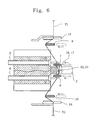
- FIG. 6 is a side view sequential to FIG. 5 illustrating the yarn splicer.
- the upper yarn Y1 held by the upper yarn suction arm S1 is clamped by the clamping member 13, while the lower yarn Y2 held by the lower yarn suction arm S2 is clamped by the clamping member 14.
- the yarn shifting levers 9 and 10 are moved to guide the yarns Y1 and Y2 into the splicing holes 16 and 17, respectively, provided in the yarn splicing member 2, as well as into the cutters 11 and 12, respectively.
- the yarns Y1 and Y2 are cut by the cutters 11 and 12, respectively, so as to form yarn ends to a prescribed length from where the yarns Y1 and Y2 are clamped by the clamping members 13 and 14, respectively.
- each of the yarns Y1 and Y2 have their core yarns stretched and thus strained, and therefore, when the cutter 11 and 12 are operated, each of the yarns Y1 and Y2 is brought into contraction. Accordingly, as will be described in detail later, each of the yarns Y1 and Y2 contracts in length and expands in thickness, so that the yarns Y1 and Y2 are caught and held by a catch-and-hold slit 21 (see FIG. 7) formed in the yarn splicing member 2, and reliably secured in the splicing holes 16 and 17, respectively.
- each of the yarns Y1 and Y2 does not slip off the yarn splicing member 2, and therefore, it is possible to prevent failure of yarn splicing.
- the core yarn of each of the yarns Y1 and Y2 can be prevented from being pulled away from the yarn splicing member 2, and therefore, the stretchability of the spliced portion of the yarns Y1 and Y2 can be ensured.
- yarn ends of a uniform length can be placed in the splicing holes 16 and 17, leading to stability of the joint.
- the yarns Y1 and Y2 are caught and held by a pair of resisting members 3 and 4, respectively, which ensures that the yarns are sucked by the holding nozzles 5 and 6 in the next step.
- the resisting members 3 and 4 are provided with a row of a number of comb-like blades, and fibers wrapped around the core yarn of each of the yarns Y1 and Y2 are caught by the comb-like blades, providing resistance against contraction.
- each of the holding nozzles 5 and 6 ceases its operation, and the yarn shifting levers 9 and 10 are activated to pull the ends of the yarns Y1 and Y2 out of the holding nozzles 5 and 6, respectively.
- the yarn holding levers 7 and 8 are activated to place the yarns Y1 and Y2 at their respective predetermined positions in the splicing holes 16 and 17.
- the yarn ends of the yarns Y1 and Y2 are placed together within the splicing holes 16 and 17.
- jets of compressed air are emitted from the splicing jet paths 22 and 23 into the splicing holes 16 and 17.
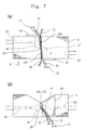
- FIG. 7 shows enlarged views of a yarn splicing member of a first embodiment, where (a) is a front view, and (b) is a view seen from the direction of arrow A in (a).
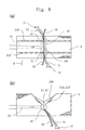
- FIG. 8 shows enlarged views of a yarn splicing member of a second embodiment, where (a) is a front view, and (b) is a view seen from the direction of arrow B in (a).
- the yarn splicing member 2 of the first embodiment includes a first splicing hole 16 on the upper side and a second splicing hole 17 on the lower side (see FIG. 7(a)).
- the splicing holes 16 and 17 are provided in parallel with each other, such that the bottom surface of the first splicing hole 16 is substantially flush with the top surface of the second splicing hole 17.
- Upper portions in cross section of the splicing holes 16 and 17 are open to guiding slits 160 and 170 (see FIG. 7(b)).
- the guiding slits 160 and 170 are provided for guiding the yarns Y1 and Y2 into the splicing holes 16 and 17, respectively, and formed to be wider than the yarns Y1 and Y2.
- the first guiding slit 160 is connected with the right end side of the first splicing hole 16, and the second guiding slit 170 is connected with the left end side of the second splicing hole 17.
- the guiding slits 160 and 170 are provided continuously so as to penetrate with each other, thereby forming a V-shaped catch-and-hold slit 21 at the intersection of the guiding slits 160 and 170.
- the upper yarn Y1 is guided through the first guiding slit 160 into the first splicing hole 16, and passes through the catch-and-hold slit 21, and thereafter the yarn Y is further guided through the second guiding slit 170 into the second splicing hole 17.
- the lower yarn Y2 is guided through the second guiding slit 170 into the second splicing hole 17, and passes through the catch-and-hold slit 21, and thereafter the yarn Y2 is further guided through the first guiding slit 160 into the first splicing hole 16.
- the upper yarn Y1 placed in the second splicing hole 17 contracts in length and expands in thickness, and the length contraction and thickness expansion allows the upper yarn Y1 to be caught and held by the catch-and-hold slit 21.
- the lower yarn Y2 placed in the first splicing hole 16 contracts in length and expands in thickness, and the length contraction and thickness expansion allows the lower yarn Y2 to be caught and held by the catch-and-hold slit 21.
- the yarns Y1 and Y2 are each elastic yarn including a stretchable core yarn, the length contraction and thickness expansion occurs due to the cutting, and the thickness of each of the yarns Y1 and Y2 having contracted in length and expanded in thickness becomes greater than the width of the narrow end of the catch-and-hold slit 21 (about 0.2 mm), so that each of the yarns Y1 and Y2 is caught and held thereby.
- jets of compressed air are emitted from the first splicing jet path 22, which leads to the first splicing hole 16, and from the second splicing jet path 23, which leads to the second splicing hole 17, so that the yarns Y1 and Y2 are twisted and spliced together.
- the yarn splicing member 2 of the second embodiment has one splicing hole 16 continuously provided in the vertical direction.
- the splicing hole 16 is open at the upper center, which leads to the guiding slit 160 (see FIG. 8(b)).
- Provided in upper and lower portions of the yarn splicing member 2 are a pair of plate members 210 and 210'.
- the plate members 210 and 210' have catch-and-hold slits 21 and 21' formed at their respective centers, and the catch-and-hold slits 21 and 21' have their narrow ends placed in the splicing hole 16.
- the yarns Y1 and Y2 are guided through the catch-and-hold slits 21 and 21', respectively, into the splicing hole 16. Thereafter, when the upper yarn Y1 is cut by the cutter 12, the upper yarn Y1 placed in the bottom side of the splicing hole 16 contracts in length and expands in thickness, and the length contraction and thickness expansion allows the upper yarn Y1 to be caught and held by the catch-and-hold slit 21' . Also, when the lower yarn Y2 is cut by the cutter 11, the lower yarn Y2 placed in the bottom side of the splicing hole 16 contracts in length and expands in thickness, and thus is caught and held by the catch-and-hold slit 21.
- the plate members 210 can be replaced with other plate members 210 with a catch-and-hold slit 21 of a different width in accordance with the thickness of the yarns that are to be spliced.
- the above-described yarn splicer 1 according to the present invention can be installed in automatic winders, spinning machines, and various other textile machines equipped with a yarn splicer. Also, the effect of the present invention can be achieved so long as the yarns that are to be spliced are spun yarns having relatively great stretchability.
Landscapes
- Spinning Or Twisting Of Yarns (AREA)
Applications Claiming Priority (1)
| Application Number | Priority Date | Filing Date | Title |
|---|---|---|---|
| JP2004364243A JP2006168923A (ja) | 2004-12-16 | 2004-12-16 | 糸継ぎ装置 |
Publications (3)
| Publication Number | Publication Date |
|---|---|
| EP1671910A2 true EP1671910A2 (fr) | 2006-06-21 |
| EP1671910A3 EP1671910A3 (fr) | 2006-08-09 |
| EP1671910B1 EP1671910B1 (fr) | 2010-04-14 |
Family
ID=35892268
Family Applications (1)
| Application Number | Title | Priority Date | Filing Date |
|---|---|---|---|
| EP20050024668 Expired - Lifetime EP1671910B1 (fr) | 2004-12-16 | 2005-11-11 | Dispositif d'épissure de fils |
Country Status (4)
| Country | Link |
|---|---|
| EP (1) | EP1671910B1 (fr) |
| JP (1) | JP2006168923A (fr) |
| CN (1) | CN1789099B (fr) |
| DE (1) | DE602005020566D1 (fr) |
Cited By (8)
| Publication number | Priority date | Publication date | Assignee | Title |
|---|---|---|---|---|
| EP3031763A1 (fr) * | 2014-12-13 | 2016-06-15 | Saurer Germany GmbH & Co. KG | Unite de canal d'epissage comprenant un canal d'insertion special pour l'air d'epissage, machine d'epissage comprenant une telle unite de canal d'epissage et machine textile comprenant une telle machine d'epissage |
| EP3031762A1 (fr) * | 2014-12-13 | 2016-06-15 | Saurer Germany GmbH & Co. KG | Unité de canal d'épissage séparée axialement comprenant deux chambres décalées radialement et des bords anti-choc tranchants entre les chambres, dispositif d'épissage comprenant une telle unité de canal d'épissage et machine textile comprenant un tel dispositif d'épissage |
| DE102015014384A1 (de) * | 2015-11-09 | 2017-05-11 | Saurer Germany Gmbh & Co. Kg | Fadenleitblechelement für eine Fadenspleissvorrichtung einer Arbeitsstelle einer Spulmaschine, Fadenspleissvorrichtung und Verfahren zum Betreiben der Arbeitsstelle |
| EP3505472A1 (fr) * | 2017-12-26 | 2019-07-03 | Murata Machinery, Ltd. | Dispositif d'assemblage de fil |
| EP3686142A1 (fr) * | 2019-01-24 | 2020-07-29 | Murata Machinery, Ltd. | Dispositif d'assemblage de fil et dispositif de bobinage de fil |
| CN112111826A (zh) * | 2020-08-27 | 2020-12-22 | 巨石集团有限公司 | 一种纱线打结器及纱线打结方法 |
| CN112301485A (zh) * | 2019-07-30 | 2021-02-02 | 日本Tmt机械株式会社 | 合成纤维纱用捻接器 |
| EP3771678A1 (fr) * | 2019-07-30 | 2021-02-03 | TMT Machinery, Inc. | Épisseur de fil synthétique |
Families Citing this family (8)
| Publication number | Priority date | Publication date | Assignee | Title |
|---|---|---|---|---|
| JP2010132359A (ja) * | 2007-03-22 | 2010-06-17 | Shima Seiki Mfg Ltd | スプライサ装置 |
| JP2009143718A (ja) * | 2007-12-18 | 2009-07-02 | Murata Mach Ltd | スプライサーノズル |
| CN101397701B (zh) * | 2008-04-07 | 2011-07-13 | 上海凯利纺织五金有限公司 | 可装卸的气路集成块及其自动空捻器 |
| DE102011111033A1 (de) * | 2011-08-19 | 2013-02-21 | Oerlikon Textile Gmbh & Co. Kg | Fadenspleißvorrichtung für eine Kreuzspulen herstellende Textilmaschine |
| CN103343411A (zh) * | 2013-07-12 | 2013-10-09 | 无锡市三达纺配有限公司 | 一种分段式空气捻接腔 |
| DE102017102432A1 (de) * | 2017-02-08 | 2018-08-09 | Saurer Germany Gmbh & Co. Kg | Spleißprisma für eine Fadenspleißvorrichtung einer Arbeitsstelle einer Kreuzspulen herstellenden Textilmaschine und Einsatzteil für das Spleißprisma |
| CN111379054B (zh) * | 2018-12-27 | 2021-04-02 | 苏州迪塔杉针织有限公司 | 一种纱线并行拼接装置 |
| CN111977465B (zh) * | 2020-08-11 | 2022-04-01 | 苏州胜幢纺织有限公司 | 一种四面弹面料弹性纱线的加工方法及加工设备 |
Citations (1)
| Publication number | Priority date | Publication date | Assignee | Title |
|---|---|---|---|---|
| JP2001199637A (ja) | 2000-01-18 | 2001-07-24 | Murata Mach Ltd | 糸継ぎ装置 |
Family Cites Families (6)
| Publication number | Priority date | Publication date | Assignee | Title |
|---|---|---|---|---|
| US3306020A (en) * | 1966-07-05 | 1967-02-28 | Spunize Company Of America Inc | Method and apparatus for splicing yarn |
| JPS59228029A (ja) * | 1983-05-17 | 1984-12-21 | Murata Mach Ltd | 紡績糸の糸継ぎ装置 |
| JPS61257877A (ja) * | 1985-04-12 | 1986-11-15 | Murata Mach Ltd | 糸継ノズルユニツト |
| DE10124832A1 (de) * | 2001-05-22 | 2002-11-28 | Schlafhorst & Co W | Fadenspleissvorrichtung |
| ITMI20021500A1 (it) * | 2002-07-09 | 2004-01-09 | Mesdan Spa | Dispositivo e procedimento per la giunzione pneumatica di fili o filati contenenti un elastomero o ad elevata torsione |
| DE10359570A1 (de) * | 2003-12-18 | 2005-07-28 | Saurer Gmbh & Co. Kg | Fadenspleißvorrichtung zum pneumatischen Verbinden von Garnen |
-
2004
- 2004-12-16 JP JP2004364243A patent/JP2006168923A/ja active Pending
-
2005
- 2005-11-11 DE DE200560020566 patent/DE602005020566D1/de not_active Expired - Lifetime
- 2005-11-11 EP EP20050024668 patent/EP1671910B1/fr not_active Expired - Lifetime
- 2005-11-25 CN CN 200510125547 patent/CN1789099B/zh not_active Expired - Fee Related
Patent Citations (1)
| Publication number | Priority date | Publication date | Assignee | Title |
|---|---|---|---|---|
| JP2001199637A (ja) | 2000-01-18 | 2001-07-24 | Murata Mach Ltd | 糸継ぎ装置 |
Cited By (9)
| Publication number | Priority date | Publication date | Assignee | Title |
|---|---|---|---|---|
| EP3031763A1 (fr) * | 2014-12-13 | 2016-06-15 | Saurer Germany GmbH & Co. KG | Unite de canal d'epissage comprenant un canal d'insertion special pour l'air d'epissage, machine d'epissage comprenant une telle unite de canal d'epissage et machine textile comprenant une telle machine d'epissage |
| EP3031762A1 (fr) * | 2014-12-13 | 2016-06-15 | Saurer Germany GmbH & Co. KG | Unité de canal d'épissage séparée axialement comprenant deux chambres décalées radialement et des bords anti-choc tranchants entre les chambres, dispositif d'épissage comprenant une telle unité de canal d'épissage et machine textile comprenant un tel dispositif d'épissage |
| DE102015014384A1 (de) * | 2015-11-09 | 2017-05-11 | Saurer Germany Gmbh & Co. Kg | Fadenleitblechelement für eine Fadenspleissvorrichtung einer Arbeitsstelle einer Spulmaschine, Fadenspleissvorrichtung und Verfahren zum Betreiben der Arbeitsstelle |
| EP3505472A1 (fr) * | 2017-12-26 | 2019-07-03 | Murata Machinery, Ltd. | Dispositif d'assemblage de fil |
| EP3686142A1 (fr) * | 2019-01-24 | 2020-07-29 | Murata Machinery, Ltd. | Dispositif d'assemblage de fil et dispositif de bobinage de fil |
| CN112301485A (zh) * | 2019-07-30 | 2021-02-02 | 日本Tmt机械株式会社 | 合成纤维纱用捻接器 |
| EP3771678A1 (fr) * | 2019-07-30 | 2021-02-03 | TMT Machinery, Inc. | Épisseur de fil synthétique |
| TWI829954B (zh) * | 2019-07-30 | 2024-01-21 | 日商Tmt機械股份有限公司 | 合成纖維紗用接續器 |
| CN112111826A (zh) * | 2020-08-27 | 2020-12-22 | 巨石集团有限公司 | 一种纱线打结器及纱线打结方法 |
Also Published As
| Publication number | Publication date |
|---|---|
| EP1671910A3 (fr) | 2006-08-09 |
| CN1789099B (zh) | 2011-12-28 |
| CN1789099A (zh) | 2006-06-21 |
| JP2006168923A (ja) | 2006-06-29 |
| EP1671910B1 (fr) | 2010-04-14 |
| DE602005020566D1 (de) | 2010-05-27 |
Similar Documents
| Publication | Publication Date | Title |
|---|---|---|
| EP1671910B1 (fr) | Dispositif d'épissure de fils | |
| JP4110415B2 (ja) | 糸継ぎ装置およびハンディー型スプライサー | |
| JP4082930B2 (ja) | 糸撚り継ぎ装置 | |
| US20030167747A1 (en) | Device for the pneumatic joining of yarns | |
| JP2016155648A (ja) | 糸継装置及び糸巻取装置 | |
| US4414798A (en) | Splicing apparatus for spun yarns | |
| JPH0812195A (ja) | あや巻きボビンを製造する繊維機械のための糸端部準備装置 | |
| US4445317A (en) | Splicing method for spun yarns | |
| EP1118570B1 (fr) | Appareil pour raccorder des fils textiles | |
| JP2018030722A (ja) | 綾巻きパッケージを製造する繊維機械の作業ユニット用の糸スプライシング装置 | |
| US4432197A (en) | Method for preventing abnormal splicing in winder | |
| TWI829982B (zh) | 絲線處理裝置 | |
| CN106698096B (zh) | 接纱机构、纱线卷绕装置以及接纱方法 | |
| US4446687A (en) | Pneumatic yarn splicing apparatus for splicing core spun yarns | |
| US4494366A (en) | Yarn end untwisting device for a pneumatic yarn splicing device | |
| CN109911710B (zh) | 用于制造交叉卷绕筒子的纺织机的工位的旋转接纱器 | |
| US4494368A (en) | Method of preventing irregular untwisting of yarn ends in splicing spun yarns | |
| US4439978A (en) | Apparatus for splicing spun yarns | |
| US4416110A (en) | Splicing apparatus for spun yarns | |
| US4505097A (en) | Method of splicing spun yarns | |
| JP3744150B2 (ja) | マルチスプライサー | |
| CN111470382B (zh) | 接纱装置及纱线卷绕装置 | |
| JP2006168924A (ja) | 糸継ぎ装置 | |
| JP3572770B2 (ja) | 空気式糸継装置 | |
| JPS58144065A (ja) | 空気式糸継装置における糸端解撚方法 |
Legal Events
| Date | Code | Title | Description |
|---|---|---|---|
| PUAI | Public reference made under article 153(3) epc to a published international application that has entered the european phase |
Free format text: ORIGINAL CODE: 0009012 |
|
| AK | Designated contracting states |
Kind code of ref document: A2 Designated state(s): AT BE BG CH CY CZ DE DK EE ES FI FR GB GR HU IE IS IT LI LT LU LV MC NL PL PT RO SE SI SK TR |
|
| AX | Request for extension of the european patent |
Extension state: AL BA HR MK YU |
|
| PUAL | Search report despatched |
Free format text: ORIGINAL CODE: 0009013 |
|
| AK | Designated contracting states |
Kind code of ref document: A3 Designated state(s): AT BE BG CH CY CZ DE DK EE ES FI FR GB GR HU IE IS IT LI LT LU LV MC NL PL PT RO SE SI SK TR |
|
| AX | Request for extension of the european patent |
Extension state: AL BA HR MK YU |
|
| 17P | Request for examination filed |
Effective date: 20061128 |
|
| 17Q | First examination report despatched |
Effective date: 20070205 |
|
| AKX | Designation fees paid |
Designated state(s): DE IT |
|
| GRAP | Despatch of communication of intention to grant a patent |
Free format text: ORIGINAL CODE: EPIDOSNIGR1 |
|
| GRAS | Grant fee paid |
Free format text: ORIGINAL CODE: EPIDOSNIGR3 |
|
| GRAA | (expected) grant |
Free format text: ORIGINAL CODE: 0009210 |
|
| AK | Designated contracting states |
Kind code of ref document: B1 Designated state(s): DE IT |
|
| REF | Corresponds to: |
Ref document number: 602005020566 Country of ref document: DE Date of ref document: 20100527 Kind code of ref document: P |
|
| PLBE | No opposition filed within time limit |
Free format text: ORIGINAL CODE: 0009261 |
|
| STAA | Information on the status of an ep patent application or granted ep patent |
Free format text: STATUS: NO OPPOSITION FILED WITHIN TIME LIMIT |
|
| PGFP | Annual fee paid to national office [announced via postgrant information from national office to epo] |
Ref country code: DE Payment date: 20101119 Year of fee payment: 6 |
|
| 26N | No opposition filed |
Effective date: 20110117 |
|
| PGFP | Annual fee paid to national office [announced via postgrant information from national office to epo] |
Ref country code: IT Payment date: 20101125 Year of fee payment: 6 |
|
| PG25 | Lapsed in a contracting state [announced via postgrant information from national office to epo] |
Ref country code: IT Free format text: LAPSE BECAUSE OF NON-PAYMENT OF DUE FEES Effective date: 20121111 |
|
| REG | Reference to a national code |
Ref country code: DE Ref legal event code: R119 Ref document number: 602005020566 Country of ref document: DE Effective date: 20130601 |
|
| PG25 | Lapsed in a contracting state [announced via postgrant information from national office to epo] |
Ref country code: DE Free format text: LAPSE BECAUSE OF NON-PAYMENT OF DUE FEES Effective date: 20130601 |