EP1672106A1 - Dispositif a came pour tricotage de tissu - Google Patents
Dispositif a came pour tricotage de tissu Download PDFInfo
- Publication number
- EP1672106A1 EP1672106A1 EP04792158A EP04792158A EP1672106A1 EP 1672106 A1 EP1672106 A1 EP 1672106A1 EP 04792158 A EP04792158 A EP 04792158A EP 04792158 A EP04792158 A EP 04792158A EP 1672106 A1 EP1672106 A1 EP 1672106A1
- Authority
- EP
- European Patent Office
- Prior art keywords
- cam
- needle
- slider
- transfer
- receiving
- Prior art date
- Legal status (The legal status is an assumption and is not a legal conclusion. Google has not performed a legal analysis and makes no representation as to the accuracy of the status listed.)
- Granted
Links
- 238000009940 knitting Methods 0.000 title claims abstract description 106
- 239000004744 fabric Substances 0.000 title claims abstract description 39
- 230000033001 locomotion Effects 0.000 claims abstract description 20
- 150000001875 compounds Chemical class 0.000 claims description 13
- 230000014759 maintenance of location Effects 0.000 claims description 12
- 230000007246 mechanism Effects 0.000 claims description 10
- 230000002123 temporal effect Effects 0.000 abstract description 3
- 238000000034 method Methods 0.000 description 15
- 230000009471 action Effects 0.000 description 12
- 230000008569 process Effects 0.000 description 10
- 230000000717 retained effect Effects 0.000 description 10
- 230000000630 rising effect Effects 0.000 description 6
- 241000761557 Lamina Species 0.000 description 3
- 230000015572 biosynthetic process Effects 0.000 description 1
- 238000006073 displacement reaction Methods 0.000 description 1
- 230000000694 effects Effects 0.000 description 1
- 230000004048 modification Effects 0.000 description 1
- 238000012986 modification Methods 0.000 description 1
- 238000004904 shortening Methods 0.000 description 1
- 125000006850 spacer group Chemical group 0.000 description 1
Images











Classifications
-
- D—TEXTILES; PAPER
- D04—BRAIDING; LACE-MAKING; KNITTING; TRIMMINGS; NON-WOVEN FABRICS
- D04B—KNITTING
- D04B15/00—Details of, or auxiliary devices incorporated in, weft knitting machines, restricted to machines of this kind
- D04B15/32—Cam systems or assemblies for operating knitting instruments
- D04B15/36—Cam systems or assemblies for operating knitting instruments for flat-bed knitting machines
- D04B15/362—Cam systems or assemblies for operating knitting instruments for flat-bed knitting machines with two needle beds in V-formation
- D04B15/365—Cam systems or assemblies for operating knitting instruments for flat-bed knitting machines with two needle beds in V-formation with provision for loop transfer from one needle bed to the other
-
- D—TEXTILES; PAPER
- D04—BRAIDING; LACE-MAKING; KNITTING; TRIMMINGS; NON-WOVEN FABRICS
- D04B—KNITTING
- D04B15/00—Details of, or auxiliary devices incorporated in, weft knitting machines, restricted to machines of this kind
- D04B15/32—Cam systems or assemblies for operating knitting instruments
-
- D—TEXTILES; PAPER
- D04—BRAIDING; LACE-MAKING; KNITTING; TRIMMINGS; NON-WOVEN FABRICS
- D04B—KNITTING
- D04B15/00—Details of, or auxiliary devices incorporated in, weft knitting machines, restricted to machines of this kind
- D04B15/32—Cam systems or assemblies for operating knitting instruments
- D04B15/36—Cam systems or assemblies for operating knitting instruments for flat-bed knitting machines
Definitions
- the invention relates to a cam apparatus for knitting a fabric, which is mounted on a carriage moving back and forth along a needle bed of a weft knitting machine and selectively drives a knitting needle disposed on the needle bed to perform an operation of knitting a fabric.
- a large number of knitting needles are arranged on a needle bed, and a cam apparatus for knitting a fabric is mounted on a carriage moving along the needle bed.
- the carriage is driven in the cam apparatus for knitting a fabric so that a knitting needle selectively moves forward into and backward from a needle bed gap, and supplies a knitting yarn to a knitting needle at the needle bed gap, thereby knitting a fabric.
- At least a pair of the needle beds is often disposed at front and back.
- a fabric is basically knitted at each needle bed.
- front and rear needle beds By use of the front and rear needle beds, it is possible to knit textures such as a rib stitch, and also knit a pouched fabric by knitting a fabric at each of the front and rear needle beds and making both ends in a width direction of the knitted fabrics continuous. Moreover, it is also possible to carry out a transferring that a knitted loop is made to move between front and rear needle beds (Refer to Japanese Examined Patent Publication JP-B2 2946325, JP-B2 2917146, JP-B2 2995464, and JP-B2 3292836, for example).
- the Japanese Examined Patent Publication JP-B2 2946325 discloses a basic idea of a method for temporarily placing a knitted loop, by use of compound needles for the knitting needles on the front and rear needle beds, from the facing needle bed onto a tongue of a slider of the compound needle retaining a knitted loop on a hook of a needle body.
- the Japanese Examined Patent Publication JP-B2 2917146 discloses a knitted loop forming method for split-knitting, a cam structure for the method, and the like, in which method the compound needles are used for the knitting needles on the front and rear needle beds, and a knitted loop formed through previous course is not knocked over but retained on a tongue of a slider, and transferred to the knitting needle on the facing needle bed and further, both of racking for shifting the needle bed and the transferring are applied.
- the Japanese Examined Patent Publication JP-B2 2995464 discloses an apparatus for the transferring and the temporal placement of a knitted loop, in which apparatus the compound needles are used on the front and rear needle beds and further, separately from the front and rear needle beds, a transfer jack is provided.
- the cited reference 4 discloses a structure of a weft knitting machine using the compound needles for the knitting needles on the front and rear needle beds, by which apparatus the transferring and the split-knitting can be carried out.
- JP-B2 2946325 JP-B2 2917146, JP-B2 2995464, and JP-B2 3292836
- JP-B2 2946325 does not disclose specific structures such as a cam apparatus for effectively driving the knitting needles.
- the transferring knitted loop is received by a hook of a needle body on the facing needle bed, so that the method of temporarily placing a knitted loop as disclosed in the Japanese Examined Patent Publication JP-B2 2946325 cannot be applied.
- the Japanese Examined Patent Publication JP-B2 2995464 discloses a cam structure for temporarily placing a knitted loop by use of a transfer jack, and a cam structure for temporarily placing a knitted loop, having a slider holding cam provided on a slider cam on the same phase of a transferring cam and a knitting cam.
- theses cam structures are complex.
- a needle is selected to one of three positions of A, H, and B, at each position of which a presser is disposed, so that change-over between driving and non-driving of needle body, slider, or the like is carried out.
- Such a structure requires not only a complex cam structure, but also a raising cam having right and left apexes with long distance therebetween.
- such a structure is not suitable to a knitting machine for producing knitted products having a short knitted width such as a glove and a sock, for which knitting machine frequently repeats back-and-forth motions at a high speed because the structure would cause a larger time loss.
- An object of the invention is to provide a cam apparatus for knitting a fabric, having a simple structure, which enables easy transferring and temporal placement of a knitted loop, and furthermore enables downsizing of a carriage.
- the invention is a cam apparatus for knitting a fabric in a weft knitting machine having front and rear needle beds facing each other at a needle bed gap, the cam apparatus comprising:
- the invention is characterized in that the group of transfer cams and the group of receiving cams are respectively provided on the carriages which are respectively disposed on the front and rear needle beds.
- each of the carriages further comprises:
- Fig. 1 is a schematic cam layout of a cam apparatus 1 for knitting a fabric according to one embodiment of the invention.
- This cam layout shows a side which receives effect of the cam, as seen through a top surface.
- the cam apparatus 1 for knitting a fabric is a weft knitting machine having front and rear needle beds facing each other at a needle bed gap, and mounted on carriages 3 and 4 which move along the respective needle beds.
- the carriage 3 moves along the front needle bed while the carriage 4 moves along the rear needle bed.
- the carriages 3 and 4 have the basically same constitution, comprising a needle body cam 10 and a slider cam 11 when using, as a knitting needle, a compound needle composed of a needle body and a slider. Knitting operation through a knitting needle can be selected for each needle by a needle selection mechanism 12.
- the needle selection mechanism 12 comprises a needle selection actuator 13, a selector float-up cam 14, a selector push-up cam 15, and a selector guide cam 16.
- a yarn guide cam 17 for driving a movable sinker which presses a knitting yarn at the needle bed gap 2
- a sinker cam 18 for guiding a knitting yarn to a knitting needle, and the like.
- selector float-up cam 14 is shown in the cam layout for convenience sake of description although a function of the selector float-up cam 14 to push up a selector from a bottom side of a needle groove is effected at a position away from bottom boards of the carriages 3 and 4 as will be hereinafter described in detail.
- selector push-up cam 15, etc. except the selector float-up cam 14 a direction toward the needle bed gap 2 is indicated as "up” while a direction backward from the needle bed gap 2 is indicated as "down”, respectively.
- a face shown in crosshatched pattern indicates an inclined face which is continuously raised from a surface of the bottom board.
- the needle body cam 10 comprises a knitting cam 20.
- the knitting cam 20 comprises a raising cam 21 including a center cam, and a guard cam 22 called as an upper cam, stitch cams 23 and 24, and the like.
- the raising cam 21 has a mountain-like shape protruding toward the needle bed gap 2.
- a guide path for moving a needle body to a knitting position is formed between the raising cam 21 and the guard cam 22 which is disposed closer to the needle bed gap 2 than the raising cam 21 is.
- the carriages 3 and 4 move back and forth in a horizontal direction of the figure.
- the stitch cams 23 and 24 are respectively disposed on both sides of the knitting cam 20 so that the needle body which has advanced toward the needle bed gap 2 can be dragged down in movement of the carriages in both directions.
- the stitch cams 23 and 24 can be relatively displaced along inclined faces of the mountain-like shape of the raising cam 21 so that a stitch density can be arranged by changing a dragged-down amount of the needle body.
- rubber cams 25 and 26 are disposed around the raising cam 21 as a center therefor, respectively in outward directions from the stitch cams 23 and 24.
- the rubber cams 25 and 26 are control cams which can be displaced to be in and out of the bottom boards of the carriages 3 and 4. In a state where the rubber cams 25 and 26 protrude from the bottom board, it is possible to make an inlay stitch for which a stretch yarn is used.
- a movable presser 30 is disposed at a position receded from the needle bed gap 2. Outside the movable presser 30 are disposed select jack half stitch cams 31 and 32, and select jack stitch cams 33 and 34.
- the select jack half stitch cams 31 and 32 are fixed cams which always protrude from the bottom board.
- the select jack stitch cams 33 and 34 are control cams which can be displaced to be in and out of the bottom board. Outside the select jack stitch cam 34 is disposed a select jack presser 35.
- Each of the carriages 3 and 4 is provided with a group of transfer cams 40 and a group of receiving cams 50.
- the group of transfer cams 40 are disposed at a downstream-side position to the knitting cam 20 in a case where the carriage 3 moves in one direction, for example leftward in the figure.
- the group of receiving cams 50 is disposed at a position facing the group of transfer cams 40. The group of transfer cams 40 and the group of receiving cams 50 are thus disposed. Accordingly, by moving the carriages 3 and 4 leftward, a knitted loop can be transferred from a front needle bed provided with the carriage 3 to a rear needle bed provided with the carriage 4.
- the group of transfer cams 40 are disposed at a position which corresponds to a position of the group of receiving cams 50 across the knitting cam 20.
- the group of receiving cams 50 At the position of the carriage 3, facing the group of transfer cams 40 of the carriage 4 across the needle bed gap 2 is disposed the group of receiving cams 50. Consequently, when the carriages 3 and 4 are made to move in a right direction, a knitted loop can be transferred from the rear needle bed provided with the carriage 4 to the front needle bed provided with carriage 3.
- Each of the group of transfer cams 40 includes a slider transfer raising cam 41, a slider transfer cam 42, and a transfer-side knitted loop receiving cam 43.
- the slider transfer cam 42 includes a cam route for maintaining a raised position of a slider toward the needle bed 2 caused by a slider cam 11, and further raising the slider.
- the slider transfer raising cam 41 is disposed between the slider cam 11 and the slider transfer cam 42.
- the slider transfer raising cam 41 is a control cam which can be displaced to be in and out of the bottom board.
- the slider transfer raising cam 41 in a protruding state conveys the slider to the cam route of the slider transfer cam 42.
- the transfer-side knitted loop receiving cam 43 is used for conveying the needle body independently or together with the slider, to the receiving position where a knitted loop is received from the opposed needle bed.
- the transfer-side knitted loop receiving cam 43 is also a control cam which can be displaced to be in and out of the bottom board. It is possible to take the knitted loop back which has been once transferred to the opposed needle bed side by making the transfer-side knitted loop receiving cam 43 protrude.
- Each of the group of receiving cams 50 includes a receiving-side knitted loop receiving cam 51, a receiving-side retention raising cam 52, and a receiving slider cam 53.
- the receiving-side knitted loop receiving cam 51 is a control cam which can be displaced to be in and out of the bottom board.
- the receiving-side knitted loop receiving cam 51 is made to protrude, thereby advancing the needle body to the needle bed gap 2 so that the needle body is conveyed to the receiving position where the knitted loop to be transferred from the opposed needle bed is received.
- the receiving-side retention raising cam 52 is a control cam which can be displaced to be in and out of the bottom board.
- the receiving-side retention raising cam 52 is made to protrude, thereby guiding the slider to the receiving slider cam 53 and advancing the slider to the needle bed gap 2 so that the knitted loop to be transferred from the opposed needle bed is taken, and it is possible to keep the state where the knitted loop is retained.
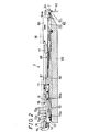
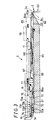
- Figs. 2 and 3 show sectional constitutions of one needle bed 60, for example, the front needle bed.
- the rear needle bed has the basically same constitution.
- On the needle bed 60 are formed needle grooves 61 at regular intervals so that knitting needles such as a compound needle 62 are contained inside the needle grooves 61.
- the compound needle 62 includes a needle body 63 and a slider 64.
- a leading tip of the needle body 63 on the needle bed 2-side is provided with a hook 63a.
- the slider 64 has a leading tip thereof on the needle bed gap 2-side formed into two separate elastic laminas nipping the needle body therewith as shown in Fig. 4 in Japanese Examined Patent Publication JP-B2 2917146 and the like.
- the elastic lamina part has steps, one of which on the leading tip side is lower with a leading tip part thereof formed to be a tongue 64a.
- the needle body 62 and the slider 63 are pressed by a spacer 65 or the like so as not to move upward away from the needle groove 61 at the time of sliding displacement upward to or downward from the needle bed gap 2.
- the needle body 63 is coupled to a needle jack 66 at a tail tip side of the needle body 63 and a leading tip side of the needle jack 66.
- the needle jack 66 has an elastic portion 66a formed at a tail tip side thereof so that the elastic portion 66a biases the needle jack 66 in a direction of moving the needle jack 66 upward from a bottom of the needle groove 61. From the needle jack 66, a needle jack butt 67 protrudes toward outside of the needle groove 61.
- the needle jack butt 67 is subjected to an action of a needle body cam 10, and drives the needle body 62 to be displaced to an advanced or retracted position with respect to the needle bed gap 2 in the needle groove 61. Also from the slider 64, a slider butt 68 protrudes toward outside of the needle groove 61. When the needle jack 66 moves inside the needle groove 61 toward the needle bed gap 2, abutment of the leading tip of the needle jack 66 onto the slider butt 68 makes it possible to push up the slider 64 together with the needle body 63 toward the needle bed gap 2.
- the slider butt 68 is made to be subjected to actions of the slider cam 11 shown in Fig. 1, and the slider raising cam 41, the slider transfer cam 42, the receiving-side retention raising cam 52, the receiving slider cam 53, and the like, it is possible to advance only the slider 64 further toward the needle bed gap 2.
- the elastic portion 66a of the needle jack 66 can be pressed by a select jack 70.
- the select jack 70 has a tail tip side thereof formed to be an elastic portion 70a which abuts on the bottom of the needle groove 61. From a leading tip side, a select jack butt 71 protrudes outward from the needle groove 61.
- the select jack butt 71 is subjected to actions of the movable presser 30 in Fig. 1, the select jack half stitch cams 31 and 32, the select jack stitch cams 33 and 34, the select jack presser 35, and the like.
- the select jack 70 is pressed inside the needle groove 61 by a selector 72.
- the selector 72 makes needle selection butts 73a, 73b, 73c, and 73d protrude outward from the needle groove 61, which needle selection butts 73a, 73b, 73c, and 73d are used for needle selection through the needle selection actuator 13 in Fig. 1.
- the selector float-up cam 14 pushes up the selector 72 from a bottom side thereof outward from the needle groove 61 so that the needle selection butts 71a, 73b, 73c, and 73d come into contact with the needle selection actuator 13 in Fig. 1.
- the needle selection butts 71a, 73b, 73c, and 73d are disposed at a plural, for example, four different positions, and four adjacent selectors 72 are provided respectively with different needle selection butts 71a, 73b, 73c, and h73d.
- a push-up butt 74 which is subjected to an action of the selector push-up cam 15.
- a push-down butt 75 protrudes outward from the needle groove 61.
- the push-down butt 75 is subjected to an action of the selector guide cam 16 in Fig. 1.
- Fig. 2 shows a needle selection state where the select jack 70 is pushed up to a position A in Fig. 1.
- Fig. 3 shows a non-needle selection state where the select jack 70 is sank into the needle groove 61 at a position B in Fig. 1.
- the select jack 70 may be positioned at a position H between the position A and the position B. At the position A, when the select jack butt 71 is sank into the needle groove 61 as a result of the action of the movable presser 30, the needle jack 66 is also sank into the needle groove 61 in conjunction therewith.
- the non-needle selection state shown in Fig. 3 is a state where the needle selection butts 73a, 73b, 73c, and 73d are sank by the needle selection actuator 13, and the selector 72 is formed so as to have a larger sliding resistance to the needle groove 61 so that the state where the selector 72, the select jack 70, and the needle jack 66 are sank into the needle groove 61 can be kept until next float-up caused by the selector float-up cam 14.
- the selector 72 In the non-needle selection state where the needle selection butts 73a, 73b, 73c, and 73d of the selector 72 are not sank by the needle selection actuator 13, as shown in Fig.2, the selector 72 has the push-up butt 74 pushed up by the selector push-up cam 15 so as to rise up inside the needle groove 61 toward the needle bed gap 2-side.
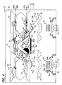
- Fig. 4 shows a control state for knitting a fabric by each of the carriages 3 and 4.
- a portion in a protruding state of the inwardly-and-outwardly-displaceable control cam is shaded.
- the raising cam 21 includes controllable inward-and-outward portions 21a and 21b which are displaced to be in and out with respect to the bottom boards of the carriages 3 and 4, and a center cam 21c.
- the stitch cams 23 and 24 have recesses 23a and 24a and different-stitch-density cam faces 23b and 24b farther away in outward directions than lowering cam faces for formation of stitch density, in the moving directions of the carriages 3 and 4.
- the movable presser 30 is divided into right and left different-stitch-density tuck pressers 30a and 30b and a center tuck presser 30c which can be controlled to be separately displaced to be in and out from the bottom board.
- the needle selection actuator 13 has action pieces 13a, 13b, 13c, and 13d which respectively press the needle selection butts 73a, 73b, 73c, and 73d shown in Figs. 2 and 3.
- the push-down butt 75 of the selector 72 coming closer from a left-hand side in Fig. 4 is pushed down at a left side of the selector guide cam 16 and until the needle selection butts 73a, 73b, 73c, and 73d reach positions of the action pieces 13a, 13b, 13c, and 13d, the selector 72 lowers.
- the push-up butt 74 rises along a rising cam face of the selector push-up cam 15 as shown as a path 74a.
- the select jack 70 also rises as shown as a path 71a of the select jack butt 71 and reaches a position A.
- the push-up butt 74 is sank into the needle groove 61 and not subjected to an action of the rising cam face of the selector push-up cam 15 so that the select jack 70 remains at a position B. That is to say, by the needle selection mechanism 12, a to-be-selected selector 72 is made to rise, by two steps, step after step among the position B, position H, and position A which are three control positions of the select jack 70.
- a needle selection is conducted by the needle selection actuator 13 and the push-up butt 74 of the selector 72 is pushed up by the selector push-up cam 15 as shown by a path 74h.
- the select jack butt 71 is also pushed up as shown by a path 71h. Even at a position higher than the position H, at next leftward movement, the select jack butt 71 abuts on a left lowering cam face of a select jack half stitch cam 31 and is pushed down to the position H.
- the selector 72 is selected for needles by the needle selection actuator 13, and the selector 72 is pushed up by the selector push-up cam 15 and then, the select jack 70 can be pushed up to the position H or the position B, or further the position A.
- the select jack 70 can be thus located at the three position B, H, and A.
- the raising cam 21 makes the inward and outward portion 21a on the left side protrude, thereby making it possible to drive the knitting needle to perform a knitting operation for a knit.
- the needle jack 67 and the slider butt 68 respectively pass through paths 67h and 68h shown in dashed lines.
- the select jack butt 71 can be made to act on the movable presser 30.
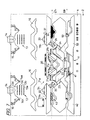
- Fig. 5 shows a control state of performing an inlay stitch in leftward movements of the carriages 3 and 4 by use of a rubber cam 25.
- knitting needles for tuck of stretch yarns such as rubber yarns are selected by the needle selection actuator 13, and the push-up butt 74 of the selector 72 is pushed up as shown by the path 74h, and the select jack butt 71 of the select jack 70 is pushed up as shown by the path 71h.
- the needle jack butt 67 passes through a position of the receiving-side knitted loop receiving cam 51 since the select jack 70 is in a state of rising to the position H.
- the receiving-side knitted loop receiving cam 51 because of being in a sank state, passes and reaches a rising cam face of the rubber cam 25. As shown by a path 67g in a dashed line, the needle jack butt 67 rises up to a tuck position at the rubber cam 25 in a protruding state, and takes at the needle bed gap 2 the stretch yarn supplied from a yarn feeding port for inlay which comes before a yarn feeding port for supplying a knitting yarn for knitting.
- this knitting needle is selected by the needle selection actuator 13, and as shown by the path 74a and the path 71a, performs the knitting operation for a knit together with the knitting needle of which the select jack 70 is pushed up to the position A, by the raising cam 21, the guide cam 22, the stitch cam 24, and the slider cam 11, and further takes a knitting yarn supplied at the needle bed portion 2.
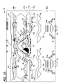
- Figs. 6 and 7 show control states at the time of transferring between the front and rear needle beds.
- Fig. 6 shows a transfer side while Fig. 7 shows a receiving side.
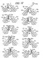
- Fig. 8 shows a transferring process at the needle bed gap 2.
- the needle selection actuator 13 on a left side conducts a needle selection to the position H or the position A.
- the inward-and-outward portion 21a of the raising cam 21 is made to protrude so that the knitting operation is carried out.
- the slider transfer raising cam 41 is made to protrude.
- the slider butt 68 of the slider 64 is guided to the cam route of the slider transfer cam 42 and as shown by a path 68t, passes through a transfer position for advancement toward the needle bed gap 2 which advancement is farther than the slider cam 11. From the carriage 4 on the receiving side, the inward-and-outward portions 21a and 21b of the raising cam 21 are not made to protrude, but the receiving-side knitted loop receiving cam 51 is made to protrude.
- the needle jack butt 67 of the needle jack 66 passes through a receiving position for advancement toward the needle bed gap 2, by the receiving-side knitted loop receiving cam 51 as shown by a path 67r.
- a circulated number 1 shows a state immediately before the knitting needle having the needle jack butt 67 abutting on a rising cam face of the raising cam 21, starts to advance toward the needle bed gap 2.
- the slider 64 has lowered while the hook 63a is open. It is assumed that on the needle body 63-side driven by the carriage 3 on the needle bed at a front side is formed a knitted loop 80 which has been knitted in the previous course.
- a circulated number 2 shows a state where the needle body 63 advances farthermost toward the needle bed gap 2 by the center cam 21c of the raising cam 21 on the carriage 3.
- the slider 64 also advances toward the needle bed gap 2, and the knitted loop 80 is transferred from the hook 63a of the needle body 63 to the tongue 64a of the slider 64.
- a circulated number 3 shows a state where the needle body 63 is made to lower to the lowermost point by the stitch cam 24. Since the slider 64 moves to the cam route of the slider transfer cam 42 by the slider transfer raising cam 41 and keeps the raised position, a top of the hook 63a of the needle body 64 lowers to a position lower than the knitted loop 80 remained on the tongue 64a of the slider 64.
- transferring is carried out.
- the slider 64 rises by the carriage 4 on the receiving side, and closes the hook 63a of the needle body 63.
- the needle body 63 on the receiving side rises by the receiving-side knitted loop receiving cam 51, and a leading tip of the hook 63a proceeds into a space between two elastic laminas of which the tongue 64a of the slider 64 on the transfer side is formed.
- the slider 64 on the transfer side rises to the uppermost position in consequence of being guided to the uppermost raised position of the cam route formed on the slider transfer cam 42.
- the needle body 63 on the receiving side rises to the uppermost position.
- the slider 64 on the transfer side starts to lower and transfers the knitted loop 80 retained on the tongue 64a to the hook 63a of the needle body 63 on the receiving side.
- the slider 64 on the transfer side lowers to a position lower than the knitted loop 80, and the knitted loop 80 is transferred to the hook 63a of the needle body 63 on the receiving side.
- the circulated number 10 shows a state where the needle body 63 on the receiving side also lowers and the hook 63a is closed by the slider 64.
- Fig. 9 shows a schematic cam layout of a cam apparatus 101 for knitting a fabric according to another embodiment of the invention.
- components corresponding to those in the embodiment of Fig. 1 will be denoted by the same reference symbols and overlapping descriptions will be omitted.
- each of carriages 103 and 104 provided on the front and rear needle beds is provided with a group of transfer cams 110 and a group of receiving cams 120.
- a slider transfer cam 111 is used instead of the slider transfer cam 42 of the group of transfer cams 40 in Fig. 1.
- a receiving slider cam 121 is used instead of the receiving slider cam 53 of the group of receiving cams 40 in Fig. 1.
- the slider transfer cam 111 and the receiving slider cam 121 are provided respectively with a cam route 111a and a groove 121a for keeping a state where the slider 64 advances to the needle bed gap 2 so that the knitted loop 80 is retained on the tongue 64a.
- a needle jack guide cam 122 and a holding presser 123 are also provided.
- the grooves of the cam routes 111a and 121a engage with a few grooves for guidance even in a state where the slider butt 68 is sank into the needle groove 61. In this regard, the aforementioned grooves of the cam routes 111a and 121a are not always necessary.
- the slider butt 68 may be used without replacing the slider transfer cam 42 and the receiving slider cam 53.
- Figs. 10 and 11 show control states at the time of transferring between the front and rear needle beds.
- Fig. 10 shows a transfer side while Fig. 11 shows a receiving side.
- the knitted loop 80 is taken on the tongue 64a of the slider 64.
- Fig. 12 shows a transferring process at the needle bed gap 2.
- the needle selection actuator 13 on a left side conducts a needle selection to the position A.
- the inward-and-outward portion 21a of the raising cam 21 is made to protrude so that the knitting operation is carried out.
- the slider transfer raising cam 41 is made to protrude.
- the slider butt 68 of the slider 64 is guided to the cam route of the slider transfer cam 111 and as shown by a path 68t, passes through a transfer position for advancement toward the needle bed gap 2 which advancement is farther than the slider cam 11.
- the needle selection actuator 13 on a right side previously selects a needle for receiving in a next course, to the position A as shown by a path 74a.
- the inward-and-outward portions 21a and 21b of the raising cam 21 are not made to protrude, but the receiving-side knitted loop receiving cam 51 is made to protrude.
- the needle jack butt 67 of the needle jack 66 passes through a receiving position for advancement toward the needle bed gap 2, by the receiving-side knitted loop receiving cam 51 as shown by a path 67r.
- the receiving-side retention raising cam 52 is made to protrude, and the slider butt 68 of the slider 64 is guided to a route for keeping a retaining state of the receiving slider cam 121 so that the retaining position can be kept as shown by a path 68r.
- a circulated symbol A shows a state immediately before the knitting needle having the needle jack butt 67 abutting on a rising cam face of the raising cam 21, starts to advance toward the needle bed gap 2.
- the slider 64 has lowered while the hook 63a is open. It is assumed that on the needle body 63-side driven by the carriage 103 on the needle bed at a front side is formed a knitted loop 80 which has been knitted in the previous course.
- a circulated symbol B shows a state where the needle body 63 advances farthermost toward the needle bed gap 2 by the center cam 21c of the raising cam 21 on the carriage 103.
- the slider 64 also advances toward the needle bed gap 2, and the knitted loop 80 is transferred from the hook 63a of the needle body 63 to the tongue 64a of the slider 64.
- a circulated symbol C shows a state where the needle body 63 is made to lower to the lowermost point by the stitch cam 24. Since the slider 64 moves to the cam route of the slider transfer cam 111 by the slider transfer raising cam 41 and keeps the raised position, a top of the hook 63a of the needle body 64 lowers to a position lower than the knitted loop 80 remained on the tongue 64a of the slider 64.
- transferring is carried out.
- the slider 64 rises by the carriage 104 on the receiving side, and closes the hook 63a of the needle body 63.
- the needle body 63 on the receiving side rises by the receiving-side knitted loop receiving cam 51, and a leading tip of the hook 63a proceeds into a space between two elastic laminas of which the tongue 64a of the slider 64 on the transfer side is formed.
- the slider butt 68 of the slider 64 on the transfer side is guided to the uppermost raised position of the cam route formed on the slider transfer cam 111 so that the slider 64 on the transfer side rises to the uppermost position.
- the slider butt 68 of the slider 64 on the receiving side is guided to the cam route of the receiving slider cam 121 by the receiving-side retention raising cam 52 so that the slider 62 on the receiving side starts to rise. Accordingly, the operations at the circulated symbols A to E in Fig. 12 are the same respectively to those at the circulated numbers 1 to 5 in Fig. 8 while the operations at the circulated symbol F and the following numbers are different from those at the circulated number 6 and the following numbers.
- the needle jack guide cam 122 is provided with a lowering face 122a and a pressing slope 122b.
- the needle jack butt 67 is guided from the lowering face 121a to the pressing slope 121b on condition that the path of the select jack butt 71 does not pass through a pressing portion 123a of the holding presser 123.
- the slider 64 rises to the uppermost position together with the needle body 63 on the receiving side.
- the slider 64 on the transfer side starts to lower and transfers the knitted loop 80 retained on the tongue 64a to the tongue 64a of the slider 64 on the receiving side.
- the slider 64 on the transfer side lowers to a position lower than the knitted loop 80, and the needle body 63 on the receiving side also lowers, in consequence whereof the knitted loop 80 is transferred to the tongue 64a of the slider 64 on the receiving side.
- the circulated symbol J shows a state where the needle body 63 and slider 64 on the receiving side lower farther, and the hook 63a is closed by the slider 64.
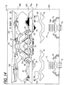
- Figs. 13 and 14 show states at the time of returning the knitted loop after transferring between the front and rear needle beds as shown in Figs. 10 to 12.
- Fig. 13 shows a transfer side while Fig. 14 shows a receiving side.
- the carriage 104 on the receiving side in Fig. 10 is now on the transfer side while the carriage 103 is now on the receiving side.
- a returning operation is carried out in the rightward movement of the carriages 103 and 104.
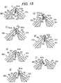
- Fig. 15 shows a returning process at the needle bed gap 2.
- a select jack stitch cam 33 is made to protrude and as shown by a path 71c of the select jack butt 71 of the select jack 70, the selector 72 is made to lower to the position B.
- the slider butt 68 of the slider 64 passes through the cam route of the receiving slider cam 121 as shown by the path 68t, and rises up to the transfer position.
- the needle jack butt 67 of the needle jack 66 keeps a certain height thereof as shown by a path 67c.
- the needle jack butt 67 of the needle jack 66 rises by the transferring knitted loop receiving cam 43 as shown by the path 67r, and the slider butt 68 of the slider 64 also rises as shown by the path 68r.
- the select jack butt 71 of the select jack 70 is pushed down by the select jack half stitch cam 32 and the select jack stitch cam 34 as shown by the paths 71a and 71h.
- a circulated symbol a in Fig. 15 shows a state corresponding to a position where the slider butt 68 is guided in accordance with the path 68t to the cam route of the receiving slider cam 121 on the carriage 104.
- a circulated symbol b shows a state where the needle body 63 on the receiving side starts to rise by the transfer-side knitted loop receiving cam 43, and the leading tip of the hook 63a is inserted into the tongue 64a of the slider 64 on the transfer side.
- a circulated symbol c shows a state where the slider 64 on the transfer side and the needle body 63 on the receiving side respectively rise to the uppermost position.
- a circulated symbol d shows a state where the slider 64 on the transfer side and the needle body 63 on the receiving side respectively lower, and the knitted loop 80 is transferred to the hook 63a of the needle body 63 on the receiving side which hook 63a is closed by the slider 64.
- a circulated symbol e shows a state where the slider 64 on the transfer side lowers with the closed needle body 63 and moves away from the knitted loop 80.
- a circulated symbol f shows a state where the needle body 63 and the slider 64 on the receiving side lower to a miss position.
- Figs. 16 and 17 show control states at the time of transferring between the front and rear needle beds similarly to Figs. 10 and 11.
- Fig. 16 shows a transfer side while Fig. 17 shows a receiving side.
- the operation ends in a continuing state for keeping the holding state where the knitted loop 80 is taken and retained on the tongue 64a of the slider 64.
- the selector 72 is selected by the following needle selection actuator 13 on the right side so that the selector push-up cam 15 pushes up the push-up butt 74 as shown by the path 74a and the select jack butt 71 of the select jack 70 has previously been made to rise up as shown by the path 71a to the position A where no abutment with the holding presser 123 is made.
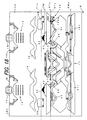
- Figs. 18 and 19 show control states for keeping the holding further. From the carriage 104 shown in Fig. 18 on the receiving side where the holding is performed on the slider 64, the select jack stitch cam 33 is made to protrude.
- the needle jack butt 67 shown in the path 67r at the previous step in Fig. 17 lowers from the path 67a to the path 67c along the lowering face 122a of the needle jack guide cam 122 from outside of the carriage 104 on the receiving side so that the needle jack butt 67 is sank by the pressing slope 122b.
- the slider butt 68 is also sank simultaneously, resulting in no more reception of the action of the receiving slider cam 121.
- the select jack butt 71 is pushed down to the position B by the select jack stitch cam 33 as shown by the path 71c and retained in the path 71c. Accordingly, the slider butt 68 keeps a position thereof as shown by the path 68c at which position the tongue 64a of the slider 64 has advanced toward the needle bed gap 2.
- the select jack butt 71 is pushed down to the position B by the select jack stitch cam 34 as shown by the path 71c and retained in the path 71c, enabling the holding to continue as shown at the circulated symbol g in Fig. 15.
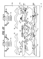
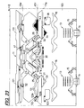
- Figs. 20, 21, 22 and 23 show states of returning the knitted loop to the needle hook 63a after the continued holding.
- the movable presser 30 (30a, 30b, and 30c) is made to protrude in a leftward course shown in the Figs. 20 and 21 while the return is to be carried out in a rightward course shown in Figs. 22 and 23 and at the same time, the selector 72 is selected by the preceding needle selection actuator 13 so that the select jack butt 71 of the select jack 70 is pushed up to the position A as shown by the path 71a.
- the slider butt 68 engages with a cam groove of the receiving slider cam 121 as shown by the path 68a and keeps a position where the tongue 64a of the slider 64 has advanced toward the needle bed gap 2. Moreover, the select jack butt 71 which has passed through the movable presser 30 (30a, 30b, and 30c), is made to lower to the position H along the select jack half stitch cam 31. In Fig. 22, similarly to Fig.
- the knitted loop 80 can be transferred from the group of transfer cams 40 or 110 to the group of receiving cams 50 or 120, and the transferred knitted loop 80 can be retained.
- the retention of the knitted loop 80 at the receiving side it is also possible to perform the holding that the transferred knitted loop 80 is retained on the tongue 64a of the slider 64 while retaining the knitted loop 80 on the needle body 63 during knitting.
- the transferring can be freely carried out between the front and rear needle beds, and it is possible to temporarily place the knitted loop 80 from one needle bed to the other needle bed and keep the holding, and what is more, retain the knitted loop 80 separately from the fabric being knitted on the other needle bed and when needed, return the knitted loop 80 from the other needle bed to the one needle bed.
- auxiliary needle beds such as an upper bed nor an idle needle
- the needle selection mechanism 12 can conduct various controls at three positions, and it is possible to simplify the needle selection mechanism 12 and even when various needle selections can be conducted, the carriages 3 and 4; 103 and 104 can be downsized.
- the downsizing of the carriages 3 and 4; 103 and 104 enables an increase in speed of movement and shortening of moving distance, so that it is possible to knit a fabric having a narrow width including a glove with a high efficiency.
- a carriage be downsized with a simple structure and transfer a knitted loop from a group of transfer cams to a group of receiving cams, and retain the transferred knitted loop, by separately disposing a route for a knitting cam and a route for transferring, and coordinating these routes each other.
- retention of the knitted loop at a receiving side it is also possible to retain the transferred knitted loop on a tongue of a slider while retaining the knitted loop on a needle body during knitting.
- a carriage In a knitting course including no transferring, a carriage can be made to move back and forth in such a narrow stroke that a knitting cam merely passes through predetermined knitting needles while only in a course including transferring, a carriage can be made to move back and forth in a stroke which is wide enough for the group of transfer cams to pass through the needles, so that a time loss can be eliminated to increase a knitting efficiency.
- transferring can be freely carried out between front and rear needle beds, and it is possible to temporarily place a knitted loop from one needle bed to the other needle bed, and what is more, retain the knitted loop separately from a fabric being knitted on the other needle bed and when needed, return the knitted loop from the other needle bed to the one needle bed.
- auxiliary needle beds such as an upper bed nor an idle needle, it is possible to knit a variety of fabrics by use of transferring for a tubular fabric and a rib fabric, and fashioning fabric and the like.
Landscapes
- Engineering & Computer Science (AREA)
- Textile Engineering (AREA)
- Knitting Machines (AREA)
Applications Claiming Priority (2)
| Application Number | Priority Date | Filing Date | Title |
|---|---|---|---|
| JP2003352984A JP4015982B2 (ja) | 2003-10-10 | 2003-10-10 | 編地編成用カム装置 |
| PCT/JP2004/014861 WO2005035852A1 (fr) | 2003-10-10 | 2004-10-07 | Dispositif a came pour tricotage de tissu |
Publications (3)
| Publication Number | Publication Date |
|---|---|
| EP1672106A1 true EP1672106A1 (fr) | 2006-06-21 |
| EP1672106A4 EP1672106A4 (fr) | 2007-01-24 |
| EP1672106B1 EP1672106B1 (fr) | 2011-07-06 |
Family
ID=34431141
Family Applications (1)
| Application Number | Title | Priority Date | Filing Date |
|---|---|---|---|
| EP04792158A Expired - Lifetime EP1672106B1 (fr) | 2003-10-10 | 2004-10-07 | Dispositif à came pour une machine à tricoter rectiligne |
Country Status (6)
| Country | Link |
|---|---|
| US (1) | US7269975B2 (fr) |
| EP (1) | EP1672106B1 (fr) |
| JP (1) | JP4015982B2 (fr) |
| KR (1) | KR101022347B1 (fr) |
| CN (1) | CN100572635C (fr) |
| WO (1) | WO2005035852A1 (fr) |
Cited By (3)
| Publication number | Priority date | Publication date | Assignee | Title |
|---|---|---|---|---|
| CN102534987A (zh) * | 2011-12-23 | 2012-07-04 | 东阳市金艺科技有限公司 | 三工位编织三角系统 |
| EP2390395A4 (fr) * | 2008-12-27 | 2014-05-07 | Shima Seiki Mfg | Machine à tricotage trame et procédé de transfert de mailles pour celle-ci |
| EP4261333A1 (fr) * | 2022-04-14 | 2023-10-18 | KARL MAYER STOLL R&D GmbH | Métier à tricoter rectiligne et procédé de fabrication d'un tricot vanisé double face, en particulier d'un tricot filigrane |
Families Citing this family (15)
| Publication number | Priority date | Publication date | Assignee | Title |
|---|---|---|---|---|
| JP4944015B2 (ja) * | 2005-03-25 | 2012-05-30 | 株式会社島精機製作所 | 横編機における筒状編地の編成方法及び横編機 |
| CN101016673B (zh) * | 2007-03-01 | 2010-05-19 | 常熟市金龙机械有限公司 | 电脑针织横编机的三角机构 |
| WO2009031315A1 (fr) * | 2007-09-05 | 2009-03-12 | Shima Seiki Mfg., Ltd. | Métier à mailles cueillies |
| CN101314888B (zh) * | 2008-07-16 | 2011-04-06 | 冯加林 | 一种采用电磁选针的三角编织控制系统 |
| KR100929606B1 (ko) * | 2008-08-12 | 2009-12-03 | 한길용 | 장갑 편직기 |
| WO2010064384A1 (fr) * | 2008-12-01 | 2010-06-10 | 株式会社島精機製作所 | Dispositif de came pour aiguille de réception de transfert |
| KR100921156B1 (ko) * | 2008-12-16 | 2009-10-12 | 주식회사 동성정밀 | 발가락양말 편성용 환편기 |
| CN101787615B (zh) * | 2010-04-21 | 2011-06-15 | 宁波慈星股份有限公司 | 针织横机的度目三角 |
| JP5788675B2 (ja) * | 2010-12-28 | 2015-10-07 | 株式会社島精機製作所 | 横編機 |
| JP5757830B2 (ja) | 2011-09-13 | 2015-08-05 | 株式会社島精機製作所 | 複合針を備える横編機、および横編機のスライダー制御方法 |
| CN102534988B (zh) * | 2011-09-20 | 2014-08-06 | 常熟市国光机械有限公司 | 电脑针织横机的机头三角系统 |
| CN103437054B (zh) * | 2013-09-02 | 2015-03-04 | 冯加林 | 一种电磁选针的横机三角编织机构及其集圈、接圈编织方法 |
| JP5913427B2 (ja) * | 2014-05-08 | 2016-04-27 | 株式会社島精機製作所 | 割増やし方法 |
| CN113388954B (zh) * | 2021-05-31 | 2025-01-14 | 桐乡市强隆机械有限公司 | 能减少织针阻力的电脑横机底板装置 |
| JP7674187B2 (ja) * | 2021-08-05 | 2025-05-09 | 株式会社島精機製作所 | 横編機によるパイル編地の編成方法 |
Family Cites Families (16)
| Publication number | Priority date | Publication date | Assignee | Title |
|---|---|---|---|---|
| JPS6120670B1 (fr) * | 1979-09-28 | 1986-05-23 | Shima Idea Center Co Ltd | |
| DE3220055A1 (de) | 1982-05-27 | 1983-12-01 | Universal Maschinenfabrik Dr. Rudolf Schieber GmbH & Co KG, 7081 Westhausen | Strick-umhaengeschloss fuer v-bett-flachstrickmaschinen mit schiebernadeln |
| DE3334040C2 (de) * | 1983-09-21 | 1986-03-13 | H. Stoll Gmbh & Co, 7410 Reutlingen | Ein- oder Mehrschloßsystem für Flachstrickmaschinen |
| JPS6120670A (ja) | 1984-07-06 | 1986-01-29 | Mitsubishi Heavy Ind Ltd | ツイント−チ型すみ肉溶接装置 |
| DE3433628C2 (de) * | 1984-09-13 | 1986-12-18 | H. Stoll Gmbh & Co, 7410 Reutlingen | Schloßsystem für Flachstrickmaschinen und Verfahren zum kombinierten Bilden und Umhängen von Maschen an Flachstrickmaschinen |
| JPS6219535A (ja) | 1985-07-17 | 1987-01-28 | Taisho Pharmaceut Co Ltd | リゾチ−ムシロツプ剤 |
| DE3537612C2 (de) * | 1985-10-23 | 1994-07-28 | Stoll & Co H | Schloßsystem für Flachstrickmaschinen |
| JP2700203B2 (ja) * | 1991-10-04 | 1998-01-19 | 株式会社島精機製作所 | 横編機におけるトランスファーの方法およびその装置 |
| JP3465174B2 (ja) | 1995-06-30 | 2003-11-10 | 株式会社島精機製作所 | 横編機におけるニット,トランスファー兼用カム |
| JP2946325B2 (ja) | 1997-05-27 | 1999-09-06 | 株式会社島精機製作所 | 編目ループの預け置き方法 |
| US6047569A (en) * | 1997-05-27 | 2000-04-11 | Shima Seiki Manufacturing, Ltd. | Method for holding a stitch loop |
| DE69809141T2 (de) * | 1997-07-11 | 2003-07-24 | Shima Seiki Mfg. Ltd., Wakayama | Verfahren zur Maschenbildung und Flachstrickmaschine dazu |
| JP2917146B2 (ja) * | 1997-07-11 | 1999-07-12 | 株式会社島精機製作所 | 編目形成方法及び該編目形成のための横編機 |
| JP3292836B2 (ja) | 1998-05-06 | 2002-06-17 | 株式会社島精機製作所 | 横編機 |
| JP2995464B2 (ja) | 1998-05-15 | 1999-12-27 | 株式会社島精機製作所 | 横編機における編目ループの預け置き装置 |
| JP3158109B2 (ja) * | 1999-02-12 | 2001-04-23 | 株式会社島精機製作所 | 横編機による編目係止方法 |
-
2003
- 2003-10-10 JP JP2003352984A patent/JP4015982B2/ja not_active Expired - Fee Related
-
2004
- 2004-10-07 WO PCT/JP2004/014861 patent/WO2005035852A1/fr not_active Ceased
- 2004-10-07 EP EP04792158A patent/EP1672106B1/fr not_active Expired - Lifetime
- 2004-10-07 US US10/574,938 patent/US7269975B2/en not_active Expired - Fee Related
- 2004-10-07 CN CNB200480029697XA patent/CN100572635C/zh not_active Expired - Fee Related
- 2004-10-07 KR KR1020067007405A patent/KR101022347B1/ko not_active Expired - Fee Related
Non-Patent Citations (2)
| Title |
|---|
| No further relevant documents disclosed * |
| See also references of WO2005035852A1 * |
Cited By (4)
| Publication number | Priority date | Publication date | Assignee | Title |
|---|---|---|---|---|
| EP2390395A4 (fr) * | 2008-12-27 | 2014-05-07 | Shima Seiki Mfg | Machine à tricotage trame et procédé de transfert de mailles pour celle-ci |
| CN102534987A (zh) * | 2011-12-23 | 2012-07-04 | 东阳市金艺科技有限公司 | 三工位编织三角系统 |
| CN102534987B (zh) * | 2011-12-23 | 2013-12-18 | 东阳市金艺科技有限公司 | 三工位编织三角系统 |
| EP4261333A1 (fr) * | 2022-04-14 | 2023-10-18 | KARL MAYER STOLL R&D GmbH | Métier à tricoter rectiligne et procédé de fabrication d'un tricot vanisé double face, en particulier d'un tricot filigrane |
Also Published As
| Publication number | Publication date |
|---|---|
| KR101022347B1 (ko) | 2011-03-22 |
| EP1672106B1 (fr) | 2011-07-06 |
| JP2005113352A (ja) | 2005-04-28 |
| CN100572635C (zh) | 2009-12-23 |
| US7269975B2 (en) | 2007-09-18 |
| US20070051138A1 (en) | 2007-03-08 |
| WO2005035852A1 (fr) | 2005-04-21 |
| EP1672106A4 (fr) | 2007-01-24 |
| JP4015982B2 (ja) | 2007-11-28 |
| KR20060096480A (ko) | 2006-09-11 |
| CN1867716A (zh) | 2006-11-22 |
Similar Documents
| Publication | Publication Date | Title |
|---|---|---|
| EP1672106B1 (fr) | Dispositif à came pour une machine à tricoter rectiligne | |
| EP0594169B1 (fr) | Métier à tricoter rectiligne avec dispositif de report | |
| EP1403409B1 (fr) | Procede de tricotage d'un motif intersia sur un tissu de tricotage et dispositif de production de programme de tricotage a cet effet | |
| KR102226578B1 (ko) | 횡편기 | |
| EP2116643B1 (fr) | Procédé de sélection d'aiguille et machine de tricotage de tissu double face | |
| CN105088499A (zh) | 加针方法 | |
| US5275022A (en) | Process for the fully-fashioned knitting of intarsia jacquard fabric | |
| JP4977383B2 (ja) | 横編機の編成用カム装置 | |
| US4662192A (en) | Flat knitting machine | |
| JP3408735B2 (ja) | トランスファージャック目移し機構を備えた横編機 | |
| EP1033428B1 (fr) | Procédé pour tenir une boucle de maille dans un métier à tricoter rectiligne | |
| JP2009068122A (ja) | 横編機およびその選針方法 | |
| CN110678593B (zh) | 横机中的添纱编织方法 | |
| EP0698679B1 (fr) | Came de tricotage et serrure | |
| EP1325973B1 (fr) | Machine de tricotage - maillage a mecanisme de transfert et technique de transfert | |
| US6668595B2 (en) | Weft knitting machine with transfer mechanism | |
| EP0604164B1 (fr) | Procédé pour le tricotage d'un dessin à croisement et dispositif pour le tricotage d'un dessin à croisement à un métier à tricoter rectiligne | |
| JP7558387B2 (ja) | 横編機によるパンチレース編地の編成方法 | |
| JP2005076143A (ja) | 横編機における三層編地編成用ヤーンフィーダ及び三層編地の編成方法 | |
| JPS6183360A (ja) | 手編機における端針作動装置 |
Legal Events
| Date | Code | Title | Description |
|---|---|---|---|
| PUAI | Public reference made under article 153(3) epc to a published international application that has entered the european phase |
Free format text: ORIGINAL CODE: 0009012 |
|
| 17P | Request for examination filed |
Effective date: 20060412 |
|
| AK | Designated contracting states |
Kind code of ref document: A1 Designated state(s): DE ES FR GB IT |
|
| DAX | Request for extension of the european patent (deleted) | ||
| RBV | Designated contracting states (corrected) |
Designated state(s): DE ES FR GB IT |
|
| A4 | Supplementary search report drawn up and despatched |
Effective date: 20061228 |
|
| 17Q | First examination report despatched |
Effective date: 20071109 |
|
| GRAP | Despatch of communication of intention to grant a patent |
Free format text: ORIGINAL CODE: EPIDOSNIGR1 |
|
| RTI1 | Title (correction) |
Free format text: CAM DEVICE FOR A FLAT BED KNITTING MACHINE |
|
| GRAS | Grant fee paid |
Free format text: ORIGINAL CODE: EPIDOSNIGR3 |
|
| GRAA | (expected) grant |
Free format text: ORIGINAL CODE: 0009210 |
|
| AK | Designated contracting states |
Kind code of ref document: B1 Designated state(s): DE ES FR GB IT |
|
| REG | Reference to a national code |
Ref country code: GB Ref legal event code: FG4D |
|
| REG | Reference to a national code |
Ref country code: DE Ref legal event code: R096 Ref document number: 602004033395 Country of ref document: DE Effective date: 20110901 |
|
| PLBE | No opposition filed within time limit |
Free format text: ORIGINAL CODE: 0009261 |
|
| STAA | Information on the status of an ep patent application or granted ep patent |
Free format text: STATUS: NO OPPOSITION FILED WITHIN TIME LIMIT |
|
| 26N | No opposition filed |
Effective date: 20120411 |
|
| GBPC | Gb: european patent ceased through non-payment of renewal fee |
Effective date: 20111007 |
|
| REG | Reference to a national code |
Ref country code: FR Ref legal event code: ST Effective date: 20120629 |
|
| REG | Reference to a national code |
Ref country code: DE Ref legal event code: R097 Ref document number: 602004033395 Country of ref document: DE Effective date: 20120411 |
|
| PG25 | Lapsed in a contracting state [announced via postgrant information from national office to epo] |
Ref country code: FR Free format text: LAPSE BECAUSE OF NON-PAYMENT OF DUE FEES Effective date: 20111102 Ref country code: GB Free format text: LAPSE BECAUSE OF NON-PAYMENT OF DUE FEES Effective date: 20111007 |
|
| PG25 | Lapsed in a contracting state [announced via postgrant information from national office to epo] |
Ref country code: ES Free format text: LAPSE BECAUSE OF FAILURE TO SUBMIT A TRANSLATION OF THE DESCRIPTION OR TO PAY THE FEE WITHIN THE PRESCRIBED TIME-LIMIT Effective date: 20111017 |
|
| PGFP | Annual fee paid to national office [announced via postgrant information from national office to epo] |
Ref country code: IT Payment date: 20210910 Year of fee payment: 18 |
|
| PGFP | Annual fee paid to national office [announced via postgrant information from national office to epo] |
Ref country code: DE Payment date: 20210831 Year of fee payment: 18 |
|
| REG | Reference to a national code |
Ref country code: DE Ref legal event code: R119 Ref document number: 602004033395 Country of ref document: DE |
|
| PG25 | Lapsed in a contracting state [announced via postgrant information from national office to epo] |
Ref country code: DE Free format text: LAPSE BECAUSE OF NON-PAYMENT OF DUE FEES Effective date: 20230503 |
|
| PG25 | Lapsed in a contracting state [announced via postgrant information from national office to epo] |
Ref country code: IT Free format text: LAPSE BECAUSE OF NON-PAYMENT OF DUE FEES Effective date: 20221007 |