EP1672121B1 - Vorrichtung und Verfahren zu Schienenbefestigungen zum Einsatz auf festen Untergründen - Google Patents
Vorrichtung und Verfahren zu Schienenbefestigungen zum Einsatz auf festen Untergründen Download PDFInfo
- Publication number
- EP1672121B1 EP1672121B1 EP05292491A EP05292491A EP1672121B1 EP 1672121 B1 EP1672121 B1 EP 1672121B1 EP 05292491 A EP05292491 A EP 05292491A EP 05292491 A EP05292491 A EP 05292491A EP 1672121 B1 EP1672121 B1 EP 1672121B1
- Authority
- EP
- European Patent Office
- Prior art keywords
- fastener
- rail
- sleeper screw
- sleeper
- spacer part
- Prior art date
- Legal status (The legal status is an assumption and is not a legal conclusion. Google has not performed a legal analysis and makes no representation as to the accuracy of the status listed.)
- Expired - Lifetime
Links
Images



Classifications
-
- E—FIXED CONSTRUCTIONS
- E01—CONSTRUCTION OF ROADS, RAILWAYS, OR BRIDGES
- E01B—PERMANENT WAY; PERMANENT-WAY TOOLS; MACHINES FOR MAKING RAILWAYS OF ALL KINDS
- E01B9/00—Fastening rails on sleepers, or the like
- E01B9/02—Fastening rails, tie-plates, or chairs directly on sleepers or foundations; Means therefor
- E01B9/28—Fastening on wooden or concrete sleepers or on masonry with clamp members
- E01B9/30—Fastening on wooden or concrete sleepers or on masonry with clamp members by resilient steel clips
- E01B9/303—Fastening on wooden or concrete sleepers or on masonry with clamp members by resilient steel clips the clip being a shaped bar
-
- E—FIXED CONSTRUCTIONS
- E01—CONSTRUCTION OF ROADS, RAILWAYS, OR BRIDGES
- E01B—PERMANENT WAY; PERMANENT-WAY TOOLS; MACHINES FOR MAKING RAILWAYS OF ALL KINDS
- E01B29/00—Laying, rebuilding, or taking-up tracks; Tools or machines therefor
- E01B29/24—Fixing or removing detachable fastening means or accessories thereof; Pre-assembling track components by detachable fastening means
Definitions
- the invention relates to a device for fastening a rail to a fixed support, this device comprising essentially a spring clip, comprising two branches joined by a central loop, (said branches being intended to be applied against a rail pad). a lag bolt passing through said central loop and screwed into said fixed support.
- the invention also relates to a rail attachment method using such a device.
- a device of this type is known to EP 0 694 649 A .
- the fasteners are pre-assembled at regular intervals on the support (typically the sleepers) in the waiting position along the location provided for the rail but outside the -this.
- the attachment consists, once the rail is laid, to put the fasteners in contact with the runners of the rail and to tighten the lag bolts until the spring fasteners exert on said rail a suitable clamping force.
- the fasteners are premounted under stress, both to not be lost and for each fastener is in a position of pre-assembly well defined.
- Some fasteners are designed to be put in place by a 180 ° rotation, others, for example according to EP 0 401 424 A by a simple translation in a direction perpendicular to the rail. In both cases, it is necessary, at the time of this operation, to unscrew the lag bolt to release the fastener, to put it in position on the runner of the rail and to screw again the lag bolt until with complete tightening of the spring clip.
- the invention aims to simplify fastening operations of the fastener, in particular by removing the unscrewing of the lag bolt to release the fastener before its introduction.
- the invention proposes a device for fixing a rail to a fixed support, of the type comprising a spring fastener, comprising two branches united by a central loop, said branches being intended to be applied against a rail pad and a lag bolt passing through said central loop, screwed into said fixed support, characterized in that it comprises an intermediate piece traversed by said lag bolt and comprising means for stressing said fastener, the stressing means being arranged to yield from a certain force transmitted by said lag bolt on said intermediate part, in order to release said fastener in the substantially unconstrained state and allow its displacement in mounting position and its final tightening.
- it In the case where it is essentially the intercalary part that is deformed, it can be made in an elastically deformable material and / or arrange its shape to facilitate the elastic deformation (slit of elasticity).
- said insert is made of electrically insulating material which allows to isolate the lag bolt relative to the fastener.
- One of the advantages of the invention lies in the fact that the transition from the premounting position to the final position is effected by a single screwing movement.
- the tool is coupled to the lag screw head once and the rotation thereof is in one and the same direction.
- the device can be completed to ensure automatic positioning of the fastener as soon as it has been released by screwing the lag bolt.
- the stressing means may comprise two ribs projecting from the lower part of the intermediate piece, the height of which, above said rib, is sufficient to allow the loosening of the fastener after passing said ribs.
- the intermediate part may comprise means of coupling with said fastener, cooperating with it, after erasing said setting means. in constraint, for its rotational displacement together with said fastener to said mounting position.
- the coupling means of the intermediate piece may consist of a relatively thick central body having a hole for the passage of the lag bolt and having a side wall whose contour matches the inner contour of said central loop of the attached.
- a similar system may be proposed in the case where the fastener is designed to be implemented by simple translation perpendicular to the rail. For example, as soon as the fastener is released, by screwing the lag bolt, the operator can push it back, foot, to the rail and continue to screw the lag bolt. It is also possible to provide a spring precompressed between the fastener in the waiting position and a fixed stop. In this case, the fastener will be pushed back to the rail by the expansion of the spring as soon as it has been released by screwing the lag bolt. The operator does not have to worry about its installation and can continue to screw the lag bolt until complete tightening of the fastener against the rail pad.
- the invention also relates to a method of mounting a fixing device between a rail and a fixed support, said device comprising a spring clip comprising two branches joined by a central loop, said branches being intended to come to apply against a rail pad and a lag bolt passing through said central loop, screwed into said fixed support, characterized in that it consists in premounting said clip on said support in a standby position adjacent to a rail location and in a state constrained by said lag bolt, the stressing means being arranged to yield from a certain force transmitted by said lag bolt, then, after placing said rail, to actuate said lag bolt until causing said stressing means to be released and releasing said fastener in the substantially unconstrained state, moving said fastener towards its mounting position and continuing actuation of said fastener bottom-up until the fastener is properly tightened on said rail pad.
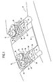
- FIG. 1 there is shown a cross member 11 equipped with two rail fastening devices 12 according to the invention, facing each other on either side of a rail slot occupied by an insulating base 14.
- the crossbar comprises such a system for each rail slot provided thereon.
- Each fastening device is of the type comprising a fastener 16 and a lag screw 18.
- the lag bolt is screwed into the fixed support constituted by the crossbar.
- the fastener 16 is made of steel and forms a spring comprising two branches 20 joined by a central loop 21. figure 1 , The branches are removed from the rail location but they are intended to come against the foot of such a rail, once the fastener is put in place and tightened.
- the fastener 16 rests on a lateral abutment 24, made of insulating material, through which the lag bolt passes.
- the lateral abutment comprises a song 26 capable of being applied along the rail pad.
- the fastener 16 is placed and stressed on the lateral stop 24, by a moderate tightening of the lag bolt.
- the lateral abutment 24 has an inclined-face groove 27, parallel to the rail and adapted to later receive rear loops 28 of the fastener.
- the fixing device comprises an intermediate piece 30 traversed by the lag bolt and comprising means 31 for stressing said fastener.
- These stressing means are arranged to yield from a certain force transmitted by the lag bolt on the intermediate piece.
- the lag bolt is screwed to transmit a moderate stress to the spring, through the insert.
- This moderate constraint makes it possible to immobilize all the elements of the fixing device in the waiting position as represented on the figure 1 .
- the cross is equipped this way and then transported and set up on the site, in this state.
- the stressing means when they give way, make it possible to release the fastener which resumes a substantially unconstrained state, which allows its movement in the mounting position and its final tightening.
- the stressing means comprise two ribs projecting from the lower part of the intermediate piece on either side thereof. The height of the intermediate piece above the ribs is sufficient to allow the relaxation of the fastener after passing said ribs.
- the intermediate part comprises coupling means with the fastener cooperating therewith, after erasure of the stressing means, for a joint displacement in rotation of the fastener and the insert, to said position of mounting.
- the coupling means of the intermediate piece comprise a central body 34, relatively thick, having a hole 35 for the passage of the lag bolt and defining a side wall whose contour fits the inner contour of the loop central of the fastener.
- the hole 35 for the passage of the lag bolt is oblong (it extends in a direction parallel to the longitudinal direction of the buckle of the fastener) while the intermediate piece 30 has a curved stop 38 parallel to said lateral wall of the central body 34 so that said side wall and the curved abutment together form a space 39 adapted to receive a median portion of the loop 21 after loosening the fastener.
- the intermediate piece and the fastener will be fully interlocked in one another and secured in rotation as well as in one another. in translation with respect to the lag bolt.
- the intermediate piece has an upper surface covering the two branches of the buckle 21 of the fastener and the head of the lag bolt 18 rests on this upper surface via a washer 36.
- the actuation key 40 of the lag bolt carries a drive member 42 of the fastener, frictionally connected to said key.
- the drive member 42 comprises two parallel fingers 44 directed downwards and engageable between each branch 20 and the central loop 21 of the fastener. These two fingers are secured to a plate to which is attached a tubular collar 46 engaged around the cylindrical handle 47 of the wrench.
- a friction material 48 is interposed between the flange and the handle.
- a stopper 50 is carried by the drive member 42. It is dimensioned and shaped to come into contact with the rail (or other element) fixed after a predetermined rotation of the drive member, in this case a rotation of a half-turn.
- the drive member 42 is therefore designed to rotate with the tightening wrench of the lag screw provided that the resistance that is exerted on him is not too important. Beyond a certain resistance, there is a sliding between the drive member and the handle 47 of the operating key.
- the ribs constituting the stressing means 31 eventually exceed the branches of the loop 21 of the fastener, which releases the latter of any constraint.
- the fastener 16 and the intermediate part 30 are completely solidified since the central part of the loop engages in the space 39 defined between the lateral surface of the central body and the curved abutment.
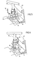
- the fastener 16 is no longer force-applied against the lateral stop, it can be rotated ( figure 5 ) until the locking stop 50 meets the rail, which corresponds to a correct positioning of the fastener relative to the rail pad 51.
- the operator does not have to worry about the positioning of the fastener, which immobiiise naturally, in final mounting position along the rail pad.
- the operator is content to continue screwing the lag bolt ( figure 6 ), which results in putting the elastic tie back under constraint while causing a slight retreat thereof until the lateral loops 28 of the fastener are positioned in the groove 27 of the lateral abutment 24.
- the situation is as illustrated on the figure 7 .
- Clamping of the fastener is carried out when the head of the lag bolt 18, resting on the washer 35, presses the intermediate piece against the lateral abutment 24, causing the lowering of the central loop 21 of the fastener, which results in a clamping effect, transmitted by the two branches 20, on the runner of the rail.
- the insert is summarized as a stop 30a integral with the lag bolt 18.
- This is a frustoconical ring of decreasing diameter from top to bottom surrounding the lag bolt 18, welded to the here or in one piece with him.
- the stressing of the fastener 16 is obtained via the stop 30a by a moderate tightening of the lag bolt.
- the stop 30a passes below the central loop 21 of the clip 16 and releases the latter which can be moved to its final position and tightened with the lag screw head.
- the distance between the stop 30a and the lag screw head is determined to accommodate the central loop 21 when the clip is released.
- the fixed support may be, for example, a crossbar supporting one or more rails.
- said crosspiece comprises, for each rail, two fixing devices as defined above, facing each other on either side of a rail location defined on said crossmember.
- the invention can also be applied to a similar assembly, fixed on a concrete slab.
Landscapes
- Engineering & Computer Science (AREA)
- Architecture (AREA)
- Civil Engineering (AREA)
- Structural Engineering (AREA)
- Mechanical Engineering (AREA)
- Railway Tracks (AREA)
- Machines For Laying And Maintaining Railways (AREA)
- Lift-Guide Devices, And Elevator Ropes And Cables (AREA)
Claims (11)
- Vorrichtung (12) zum Befestigen einer Schiene an einem stationären Träger, des Typs, der eine Befestigung (16) aufweist, die eine Feder bildet, die zwei Bügel aufweist, die durch eine zentrale Schleife verbunden sind, wobei die Bügel dazu bestimmt sind, sich gegen einen Schienenfuß (51) und eine Schienenschraube (18) zu legen, die die zentrale Schleife durchquert, die in den stationären Träger geschraubt ist, dadurch gekennzeichnet, daß sie ein Zwischenteil (30) aufweist, das von der Schienenschraube (18) durchquert wird und Mittel zum Spannen (31) der Befestigung aufweist, wobei die Mittel zum Spannen eingerichtet sind, um bei einer bestimmten Kraft, die von der Schienenschraube auf das Zwischenteil übertragen wird, nachzugeben, um die Befestigung in im Wesentlichen ungespannten Zustand freizugeben und ihr Verschieben in Montageposition sowie ihr endgültiges Spannen zu erlauben.
- Vorrichtung nach Anspruch 1, dadurch gekennzeichnet, daß die Mittel zum Spannen zwei Rippen (31) aufweisen, die am unteren Teil des Zwischenteils vorstehen, wobei dessen Höhe über den Rippen ausreichend ist, um das Freigeben der Befestigung nach dem Hinausgehen über die Rippen zu erlauben.
- Vorrichtung nach Anspruch 1 oder 2, dadurch gekennzeichnet, daß das Zwischenteil Mittel zum Koppeln mit der Befestigung aufweist, die mit dieser nach dem Hinausgehen der Mittel zum Spannen zu dessen Drehbewegung gemeinsam mit der Befestigung zu der Montageposition zusammenwirken.
- Vorrichtung nach Anspruch 3, dadurch gekennzeichnet, daß die Mittel zum Koppeln des Zwischenteils einen zentralen Körper (34) aufweisen, der eine Öffnung (35) zum Durchgehen der Schienenschraube und eine Seitenwand aufweist, deren Kontur sich an die Innenkontur der zentralen Schleife der Befestigung anpaßt.
- Vorrichtung nach Anspruch 3 oder 4, dadurch gekennzeichnet, daß die Öffnung (35) für das Durchgehen der Schienenschraube länglich ist und daß das Zwischenteil einen Raum (39) aufweist, der einen mittleren Teil der Schleife nach dem Freigeben der Befestigung aufnehmen kann.
- Vorrichtung nach einem der vorhergehenden Ansprüche, dadurch gekennzeichnet, daß sie einen seitlichen Anschlag (24) aufweist, der sich entlang eines Schienenfußes anlegen kann, und auf dem die Befestigung liegt und in einer Vormontageposition gespannt wird.
- Vorrichtung nach Anspruch 1, dadurch gekennzeichnet, daß das Zwischenteil ein Anschlag (30a) ist, der fest mit der Schienenschraube (18) verbunden ist.
- Vorrichtung nach Anspruch 7, dadurch gekennzeichnet, daß der Anschlag ein Kegelstumpfring ist, der die Schienenschraube umgibt.
- Bahngleisschwelle, dadurch gekennzeichnet, daß sie für jede Schienenlage, welche sie aufweist, mit zwei Befestigungsvorrichtungen (12) nach einem der vorhergehenden Ansprüche, die einander zu beiden Seiten der Schienenlage gegenüberliegen, ausgestattet ist.
- Bahngleisschwelle nach Anspruch 9, dadurch gekennzeichnet, daß die Schienenlage mit einer Isoliersohle (14) abgedeckt ist.
- Verfahren zur Montage einer Befestigungsvorrichtung zwischen einer Schiene (12) und einem stationären Träger, wobei die Vorrichtung eine Befestigung (16) aufweist, die eine Feder bildet, die zwei Bügel aufweist, die durch eine zentrale Schleife verbunden sind, wobei die Bügel dazu bestimmt sind, sich gegen einen Schienenfuß (51) und eine Schienenschraube (28) zu legen, die die zentrale Schleife, die in den stationären Träger geschraubt ist, durchquert, dadurch gekennzeichnet, daß es darin besteht, die Befestigung (16) auf den Träger in einer Wartestellung neben einer Schienenlage und im durch die Schienenschraube gespannten Zustand (31) vorzumontieren, wobei die Mittel zum Spannen (31) eingerichtet sind, um ab einer bestimmten Kraft, die von der Schienenschraube (18) übertragen wird, nachzugeben, und dann, nach dem Anbringen der Schiene die Schienenschraube zu betätigen, bis die Mittel zum Spannen nachgeben und die Befestigung in dem im Wesentlichen ungespannten Zustand freigeben, die Befestigung zu ihrer Montageposition zu bewegen und das Betätigen der Schienenschraube bis zu einem geeigneten Spannen der Befestigung auf dem Schienenfuß fortzusetzen.
Applications Claiming Priority (1)
| Application Number | Priority Date | Filing Date | Title |
|---|---|---|---|
| FR0412786A FR2878867B1 (fr) | 2004-12-02 | 2004-12-02 | Dispositif et procede de fixation de rail a un support fixe |
Publications (2)
| Publication Number | Publication Date |
|---|---|
| EP1672121A1 EP1672121A1 (de) | 2006-06-21 |
| EP1672121B1 true EP1672121B1 (de) | 2008-09-03 |
Family
ID=34951012
Family Applications (1)
| Application Number | Title | Priority Date | Filing Date |
|---|---|---|---|
| EP05292491A Expired - Lifetime EP1672121B1 (de) | 2004-12-02 | 2005-11-24 | Vorrichtung und Verfahren zu Schienenbefestigungen zum Einsatz auf festen Untergründen |
Country Status (5)
| Country | Link |
|---|---|
| EP (1) | EP1672121B1 (de) |
| AT (1) | ATE407260T1 (de) |
| DE (1) | DE602005009470D1 (de) |
| ES (1) | ES2317170T3 (de) |
| FR (1) | FR2878867B1 (de) |
Families Citing this family (7)
| Publication number | Priority date | Publication date | Assignee | Title |
|---|---|---|---|---|
| DE102007053901B3 (de) * | 2007-11-09 | 2009-05-20 | Db Netz Ag | Vorrichtung zur Montage und Demontage eines Befestigungsmittels, insbesondere eines Schienenbefestigungsmittels auf einem Tragkörper |
| ES2390793B1 (es) * | 2010-02-04 | 2013-09-30 | Administrador De Infraestructuras Ferroviarias (Adif) | Llave de apriete manual controlado |
| RU2437979C1 (ru) * | 2010-05-07 | 2011-12-27 | Открытое акционерное общество Научно-внедренческий центр "Путевые машины" | Способ сборки рельсовых звеньев при бесподкладочном типе скреплений |
| RU2434985C1 (ru) * | 2010-06-07 | 2011-11-27 | Федеральное государственное образовательное учреждение высшего профессионального образования "Петербургский государственный университет путей сообщения" | Промежуточное рельсовое скрепление пути на бетонном основании |
| CN102619149B (zh) * | 2011-01-27 | 2014-01-08 | 中铁十一局集团有限公司 | 板式无砟轨道i型板扣件的定位装置及快速定位方法 |
| GB2552817A (en) * | 2016-08-11 | 2018-02-14 | Pandrol Ltd | Improved screwed fastening system for railway rails |
| CN108625235B (zh) * | 2018-07-18 | 2024-10-11 | 江苏贤君科技有限公司 | 一种轨道扣件安装方法及轨道扣件加压装置 |
Family Cites Families (6)
| Publication number | Priority date | Publication date | Assignee | Title |
|---|---|---|---|---|
| DE8906790U1 (de) * | 1989-06-02 | 1989-08-31 | Vossloh-Werke GmbH, 58791 Werdohl | Schienenbefestigung auf Betonschwellen od.dgl. mittels elastischer Spannklemmen |
| FR2647821B1 (fr) * | 1989-06-02 | 1991-09-20 | Allevard Ind Sa | Dispositif de fixation de rail de voie ferree sur un support |
| DE4238757C2 (de) * | 1992-11-10 | 2000-12-14 | Deutsche Bahn Ag | Positioniereinrichtung |
| IT1267841B1 (it) * | 1994-07-27 | 1997-02-18 | Nuove Off Mecc Cinel S P A | Dispositivo di attacco elastico per il fissaggio di rotaie su mezzi di supporto |
| FR2745216B1 (fr) * | 1996-02-23 | 1998-05-22 | Turripinoise De Mecanique Sa S | Machine de vissage et de devissage de boulons ou de tire-fonds |
| DE19824458C2 (de) * | 1998-05-30 | 2001-06-28 | Pfleiderer Infrastrukturt Gmbh | Vorrichtung zur Befestigung von Schienen auf Schwellen bei schienengeführten Verkehrswegen |
-
2004
- 2004-12-02 FR FR0412786A patent/FR2878867B1/fr not_active Expired - Fee Related
-
2005
- 2005-11-24 ES ES05292491T patent/ES2317170T3/es not_active Expired - Lifetime
- 2005-11-24 DE DE602005009470T patent/DE602005009470D1/de not_active Expired - Lifetime
- 2005-11-24 EP EP05292491A patent/EP1672121B1/de not_active Expired - Lifetime
- 2005-11-24 AT AT05292491T patent/ATE407260T1/de not_active IP Right Cessation
Also Published As
| Publication number | Publication date |
|---|---|
| EP1672121A1 (de) | 2006-06-21 |
| ATE407260T1 (de) | 2008-09-15 |
| DE602005009470D1 (de) | 2008-10-16 |
| ES2317170T3 (es) | 2009-04-16 |
| FR2878867A1 (fr) | 2006-06-09 |
| FR2878867B1 (fr) | 2007-04-20 |
Similar Documents
| Publication | Publication Date | Title |
|---|---|---|
| EP0498742A1 (de) | Vorrichtung zum provisorischen Festhalten von Hebe-Anker an metallischer Oberfläche während des Giessens und Verhärtens von Betonfertigteilen | |
| WO2007113405A1 (fr) | Ecrou pour la fixation d'un pare-brise d'aeronef et dispositif de fixation d'un pare-brise d'aeronef incorporant ledit ecrou | |
| EP0455594B1 (de) | Vorrichtung zum Befestigen einer Eisenbahnschiene an einer Schwelle | |
| EP1672121A1 (de) | Vorrichtung und Verfahren zu Schienenbefestigungen zum Einsatz auf festen Untergründen | |
| FR2578906A1 (fr) | Dispositif de soutenement du toit pour mines et procede et outil pour sa mise en place | |
| WO1995020070A1 (fr) | Dispositif de fixation pour rail de chemin de fer | |
| FR2632584A1 (fr) | Systeme pour le montage amovible d'un dispositif portable sur une automobile ou analogue | |
| FR2826390A1 (fr) | Dispositif de fixation pour un revetement isolant de batiment | |
| CA1326224C (fr) | Dispositif de fixation elastique rapide d'un rail de chemin de fer | |
| FR2831898A1 (fr) | Procede de construction d'une voie ferree sur une dalle de beton et selle provisoire pour la mise en oeuvre de ce procede | |
| FR2959249A1 (fr) | Systeme de fixation de rail a attache elastique | |
| WO1990015192A1 (fr) | Dispositif de fixation de rail de voie ferree sur un support | |
| FR2634801A1 (fr) | Dispositif de support et de fixation pour rail de chemin de fer | |
| EP0002639B1 (de) | Vorrichtung zur elastischen Befestigung einer Schiene auf einen Träger | |
| EP0112766A1 (de) | Scheibenbremssattel mit entblockbarer Verstärkung | |
| FR2865225A1 (fr) | Ensemble-support d'appareil de voie pour voie en chaussee, et utilisation d'un tel ensemble-support pour la fixation d'un appareil de voie en rail a gorge ou vignole. | |
| EP0199628A1 (de) | Sicherheitssteigbügel für den Reitsport | |
| EP0943733B1 (de) | Elastische Schienenbefestigung, insbesondere für eine Backenschiene | |
| CA1277685C (fr) | Dispositif destine a la fixation d'une chaussure sur un ski de fond | |
| FR2542402A1 (fr) | Perfectionnement au maintien axial des segments d'un frein a tambour et segment de frein a tambour equipe d'un dispositif de maintien axial | |
| EP2982806B1 (de) | Entleerungsvorrichtung eines wc-tanks zum austausch einer vorherigen entleerungsvorrichtung | |
| EP2048286A1 (de) | Element zum Befestigen eines Trägers einer Leitplanke auf einer Unterlage | |
| KR200356219Y1 (ko) | 타이어용 미끄럼 방지장치 | |
| FR2571758A1 (fr) | Dispositif d'attache elastique pour rail de voie ferree | |
| EP3006164B1 (de) | Antirotations-haltevorrichtung für zubehörteil, das auf einer drehschraube montiert ist und schraubungsverfahren |
Legal Events
| Date | Code | Title | Description |
|---|---|---|---|
| PUAI | Public reference made under article 153(3) epc to a published international application that has entered the european phase |
Free format text: ORIGINAL CODE: 0009012 |
|
| AK | Designated contracting states |
Kind code of ref document: A1 Designated state(s): AT BE BG CH CY CZ DE DK EE ES FI FR GB GR HU IE IS IT LI LT LU LV MC NL PL PT RO SE SI SK TR |
|
| AX | Request for extension of the european patent |
Extension state: AL BA HR MK YU |
|
| 17P | Request for examination filed |
Effective date: 20061205 |
|
| 17Q | First examination report despatched |
Effective date: 20070105 |
|
| AKX | Designation fees paid |
Designated state(s): AT BE BG CH CY CZ DE DK EE ES FI FR GB GR HU IE IS IT LI LT LU LV MC NL PL PT RO SE SI SK TR |
|
| GRAP | Despatch of communication of intention to grant a patent |
Free format text: ORIGINAL CODE: EPIDOSNIGR1 |
|
| GRAS | Grant fee paid |
Free format text: ORIGINAL CODE: EPIDOSNIGR3 |
|
| GRAA | (expected) grant |
Free format text: ORIGINAL CODE: 0009210 |
|
| AK | Designated contracting states |
Kind code of ref document: B1 Designated state(s): AT BE BG CH CY CZ DE DK EE ES FI FR GB GR HU IE IS IT LI LT LU LV MC NL PL PT RO SE SI SK TR |
|
| REG | Reference to a national code |
Ref country code: GB Ref legal event code: FG4D Free format text: NOT ENGLISH |
|
| REG | Reference to a national code |
Ref country code: CH Ref legal event code: EP |
|
| REG | Reference to a national code |
Ref country code: IE Ref legal event code: FG4D Free format text: LANGUAGE OF EP DOCUMENT: FRENCH |
|
| REF | Corresponds to: |
Ref document number: 602005009470 Country of ref document: DE Date of ref document: 20081016 Kind code of ref document: P |
|
| PG25 | Lapsed in a contracting state [announced via postgrant information from national office to epo] |
Ref country code: LT Free format text: LAPSE BECAUSE OF FAILURE TO SUBMIT A TRANSLATION OF THE DESCRIPTION OR TO PAY THE FEE WITHIN THE PRESCRIBED TIME-LIMIT Effective date: 20080903 Ref country code: NL Free format text: LAPSE BECAUSE OF FAILURE TO SUBMIT A TRANSLATION OF THE DESCRIPTION OR TO PAY THE FEE WITHIN THE PRESCRIBED TIME-LIMIT Effective date: 20080903 |
|
| PG25 | Lapsed in a contracting state [announced via postgrant information from national office to epo] |
Ref country code: SI Free format text: LAPSE BECAUSE OF FAILURE TO SUBMIT A TRANSLATION OF THE DESCRIPTION OR TO PAY THE FEE WITHIN THE PRESCRIBED TIME-LIMIT Effective date: 20080903 Ref country code: AT Free format text: LAPSE BECAUSE OF FAILURE TO SUBMIT A TRANSLATION OF THE DESCRIPTION OR TO PAY THE FEE WITHIN THE PRESCRIBED TIME-LIMIT Effective date: 20080903 Ref country code: FI Free format text: LAPSE BECAUSE OF FAILURE TO SUBMIT A TRANSLATION OF THE DESCRIPTION OR TO PAY THE FEE WITHIN THE PRESCRIBED TIME-LIMIT Effective date: 20080903 Ref country code: LV Free format text: LAPSE BECAUSE OF FAILURE TO SUBMIT A TRANSLATION OF THE DESCRIPTION OR TO PAY THE FEE WITHIN THE PRESCRIBED TIME-LIMIT Effective date: 20080903 |
|
| NLV1 | Nl: lapsed or annulled due to failure to fulfill the requirements of art. 29p and 29m of the patents act | ||
| REG | Reference to a national code |
Ref country code: IE Ref legal event code: FD4D |
|
| REG | Reference to a national code |
Ref country code: ES Ref legal event code: FG2A Ref document number: 2317170 Country of ref document: ES Kind code of ref document: T3 |
|
| PG25 | Lapsed in a contracting state [announced via postgrant information from national office to epo] |
Ref country code: IE Free format text: LAPSE BECAUSE OF FAILURE TO SUBMIT A TRANSLATION OF THE DESCRIPTION OR TO PAY THE FEE WITHIN THE PRESCRIBED TIME-LIMIT Effective date: 20080903 Ref country code: BG Free format text: LAPSE BECAUSE OF FAILURE TO SUBMIT A TRANSLATION OF THE DESCRIPTION OR TO PAY THE FEE WITHIN THE PRESCRIBED TIME-LIMIT Effective date: 20081203 |
|
| PG25 | Lapsed in a contracting state [announced via postgrant information from national office to epo] |
Ref country code: IS Free format text: LAPSE BECAUSE OF FAILURE TO SUBMIT A TRANSLATION OF THE DESCRIPTION OR TO PAY THE FEE WITHIN THE PRESCRIBED TIME-LIMIT Effective date: 20090103 Ref country code: PT Free format text: LAPSE BECAUSE OF FAILURE TO SUBMIT A TRANSLATION OF THE DESCRIPTION OR TO PAY THE FEE WITHIN THE PRESCRIBED TIME-LIMIT Effective date: 20090203 Ref country code: CZ Free format text: LAPSE BECAUSE OF FAILURE TO SUBMIT A TRANSLATION OF THE DESCRIPTION OR TO PAY THE FEE WITHIN THE PRESCRIBED TIME-LIMIT Effective date: 20080903 Ref country code: SK Free format text: LAPSE BECAUSE OF FAILURE TO SUBMIT A TRANSLATION OF THE DESCRIPTION OR TO PAY THE FEE WITHIN THE PRESCRIBED TIME-LIMIT Effective date: 20080903 Ref country code: RO Free format text: LAPSE BECAUSE OF FAILURE TO SUBMIT A TRANSLATION OF THE DESCRIPTION OR TO PAY THE FEE WITHIN THE PRESCRIBED TIME-LIMIT Effective date: 20080903 |
|
| BERE | Be: lapsed |
Owner name: RAILTECH INTERNATIONAL Effective date: 20081130 |
|
| PG25 | Lapsed in a contracting state [announced via postgrant information from national office to epo] |
Ref country code: MC Free format text: LAPSE BECAUSE OF NON-PAYMENT OF DUE FEES Effective date: 20081130 |
|
| PLBE | No opposition filed within time limit |
Free format text: ORIGINAL CODE: 0009261 |
|
| STAA | Information on the status of an ep patent application or granted ep patent |
Free format text: STATUS: NO OPPOSITION FILED WITHIN TIME LIMIT |
|
| PG25 | Lapsed in a contracting state [announced via postgrant information from national office to epo] |
Ref country code: EE Free format text: LAPSE BECAUSE OF FAILURE TO SUBMIT A TRANSLATION OF THE DESCRIPTION OR TO PAY THE FEE WITHIN THE PRESCRIBED TIME-LIMIT Effective date: 20080903 Ref country code: DK Free format text: LAPSE BECAUSE OF FAILURE TO SUBMIT A TRANSLATION OF THE DESCRIPTION OR TO PAY THE FEE WITHIN THE PRESCRIBED TIME-LIMIT Effective date: 20080903 |
|
| 26N | No opposition filed |
Effective date: 20090604 |
|
| PG25 | Lapsed in a contracting state [announced via postgrant information from national office to epo] |
Ref country code: BE Free format text: LAPSE BECAUSE OF NON-PAYMENT OF DUE FEES Effective date: 20081130 |
|
| PG25 | Lapsed in a contracting state [announced via postgrant information from national office to epo] |
Ref country code: SE Free format text: LAPSE BECAUSE OF FAILURE TO SUBMIT A TRANSLATION OF THE DESCRIPTION OR TO PAY THE FEE WITHIN THE PRESCRIBED TIME-LIMIT Effective date: 20081203 |
|
| PG25 | Lapsed in a contracting state [announced via postgrant information from national office to epo] |
Ref country code: PL Free format text: LAPSE BECAUSE OF FAILURE TO SUBMIT A TRANSLATION OF THE DESCRIPTION OR TO PAY THE FEE WITHIN THE PRESCRIBED TIME-LIMIT Effective date: 20080903 |
|
| REG | Reference to a national code |
Ref country code: CH Ref legal event code: PL |
|
| PG25 | Lapsed in a contracting state [announced via postgrant information from national office to epo] |
Ref country code: LU Free format text: LAPSE BECAUSE OF NON-PAYMENT OF DUE FEES Effective date: 20081124 Ref country code: HU Free format text: LAPSE BECAUSE OF FAILURE TO SUBMIT A TRANSLATION OF THE DESCRIPTION OR TO PAY THE FEE WITHIN THE PRESCRIBED TIME-LIMIT Effective date: 20090304 Ref country code: CY Free format text: LAPSE BECAUSE OF FAILURE TO SUBMIT A TRANSLATION OF THE DESCRIPTION OR TO PAY THE FEE WITHIN THE PRESCRIBED TIME-LIMIT Effective date: 20080903 |
|
| PG25 | Lapsed in a contracting state [announced via postgrant information from national office to epo] |
Ref country code: TR Free format text: LAPSE BECAUSE OF FAILURE TO SUBMIT A TRANSLATION OF THE DESCRIPTION OR TO PAY THE FEE WITHIN THE PRESCRIBED TIME-LIMIT Effective date: 20080903 |
|
| PG25 | Lapsed in a contracting state [announced via postgrant information from national office to epo] |
Ref country code: GR Free format text: LAPSE BECAUSE OF FAILURE TO SUBMIT A TRANSLATION OF THE DESCRIPTION OR TO PAY THE FEE WITHIN THE PRESCRIBED TIME-LIMIT Effective date: 20081204 Ref country code: CH Free format text: LAPSE BECAUSE OF NON-PAYMENT OF DUE FEES Effective date: 20091130 Ref country code: LI Free format text: LAPSE BECAUSE OF NON-PAYMENT OF DUE FEES Effective date: 20091130 |
|
| REG | Reference to a national code |
Ref country code: FR Ref legal event code: PLFP Year of fee payment: 11 |
|
| REG | Reference to a national code |
Ref country code: FR Ref legal event code: PLFP Year of fee payment: 12 |
|
| REG | Reference to a national code |
Ref country code: FR Ref legal event code: PLFP Year of fee payment: 13 |
|
| PGFP | Annual fee paid to national office [announced via postgrant information from national office to epo] |
Ref country code: IT Payment date: 20201112 Year of fee payment: 16 Ref country code: FR Payment date: 20201110 Year of fee payment: 16 Ref country code: ES Payment date: 20201221 Year of fee payment: 16 Ref country code: GB Payment date: 20201118 Year of fee payment: 16 Ref country code: DE Payment date: 20201109 Year of fee payment: 16 |
|
| REG | Reference to a national code |
Ref country code: DE Ref legal event code: R119 Ref document number: 602005009470 Country of ref document: DE |
|
| GBPC | Gb: european patent ceased through non-payment of renewal fee |
Effective date: 20211124 |
|
| PG25 | Lapsed in a contracting state [announced via postgrant information from national office to epo] |
Ref country code: GB Free format text: LAPSE BECAUSE OF NON-PAYMENT OF DUE FEES Effective date: 20211124 Ref country code: DE Free format text: LAPSE BECAUSE OF NON-PAYMENT OF DUE FEES Effective date: 20220601 |
|
| PG25 | Lapsed in a contracting state [announced via postgrant information from national office to epo] |
Ref country code: FR Free format text: LAPSE BECAUSE OF NON-PAYMENT OF DUE FEES Effective date: 20211130 |
|
| PG25 | Lapsed in a contracting state [announced via postgrant information from national office to epo] |
Ref country code: IT Free format text: LAPSE BECAUSE OF NON-PAYMENT OF DUE FEES Effective date: 20211124 |
|
| REG | Reference to a national code |
Ref country code: ES Ref legal event code: FD2A Effective date: 20230214 |
|
| PG25 | Lapsed in a contracting state [announced via postgrant information from national office to epo] |
Ref country code: ES Free format text: LAPSE BECAUSE OF NON-PAYMENT OF DUE FEES Effective date: 20211125 |