EP1672132A2 - Dispositif pour assurer un débit constant d'un réservoir d'une fluide - Google Patents
Dispositif pour assurer un débit constant d'un réservoir d'une fluide Download PDFInfo
- Publication number
- EP1672132A2 EP1672132A2 EP05026696A EP05026696A EP1672132A2 EP 1672132 A2 EP1672132 A2 EP 1672132A2 EP 05026696 A EP05026696 A EP 05026696A EP 05026696 A EP05026696 A EP 05026696A EP 1672132 A2 EP1672132 A2 EP 1672132A2
- Authority
- EP
- European Patent Office
- Prior art keywords
- diaphragm
- curve
- control
- liquid
- control element
- Prior art date
- Legal status (The legal status is an assumption and is not a legal conclusion. Google has not performed a legal analysis and makes no representation as to the accuracy of the status listed.)
- Granted
Links
- 239000012530 fluid Substances 0.000 title claims abstract description 20
- 239000007788 liquid Substances 0.000 claims description 47
- 230000002706 hydrostatic effect Effects 0.000 claims description 32
- 238000005096 rolling process Methods 0.000 claims description 12
- 230000005540 biological transmission Effects 0.000 claims description 10
- 239000000725 suspension Substances 0.000 claims description 9
- 230000014759 maintenance of location Effects 0.000 claims description 6
- 230000001105 regulatory effect Effects 0.000 abstract description 2
- 230000001419 dependent effect Effects 0.000 abstract 1
- XLYOFNOQVPJJNP-UHFFFAOYSA-N water Substances O XLYOFNOQVPJJNP-UHFFFAOYSA-N 0.000 description 11
- 125000006850 spacer group Chemical group 0.000 description 6
- 230000001276 controlling effect Effects 0.000 description 5
- 238000010276 construction Methods 0.000 description 3
- 238000006073 displacement reaction Methods 0.000 description 3
- 238000010586 diagram Methods 0.000 description 2
- 238000000034 method Methods 0.000 description 2
- 238000011144 upstream manufacturing Methods 0.000 description 2
- 230000004913 activation Effects 0.000 description 1
- 230000033228 biological regulation Effects 0.000 description 1
- 230000006835 compression Effects 0.000 description 1
- 238000007906 compression Methods 0.000 description 1
- 230000008602 contraction Effects 0.000 description 1
- 230000008878 coupling Effects 0.000 description 1
- 238000010168 coupling process Methods 0.000 description 1
- 238000005859 coupling reaction Methods 0.000 description 1
- 230000007423 decrease Effects 0.000 description 1
- 230000000694 effects Effects 0.000 description 1
- 230000008030 elimination Effects 0.000 description 1
- 238000003379 elimination reaction Methods 0.000 description 1
- 238000009434 installation Methods 0.000 description 1
- 230000003068 static effect Effects 0.000 description 1
- 230000008961 swelling Effects 0.000 description 1
Images




Classifications
-
- F—MECHANICAL ENGINEERING; LIGHTING; HEATING; WEAPONS; BLASTING
- F16—ENGINEERING ELEMENTS AND UNITS; GENERAL MEASURES FOR PRODUCING AND MAINTAINING EFFECTIVE FUNCTIONING OF MACHINES OR INSTALLATIONS; THERMAL INSULATION IN GENERAL
- F16K—VALVES; TAPS; COCKS; ACTUATING-FLOATS; DEVICES FOR VENTING OR AERATING
- F16K3/00—Gate valves or sliding valves, i.e. cut-off apparatus with closing members having a sliding movement along the seat for opening and closing
- F16K3/02—Gate valves or sliding valves, i.e. cut-off apparatus with closing members having a sliding movement along the seat for opening and closing with flat sealing faces; Packings therefor
- F16K3/0254—Gate valves or sliding valves, i.e. cut-off apparatus with closing members having a sliding movement along the seat for opening and closing with flat sealing faces; Packings therefor being operated by particular means
-
- E—FIXED CONSTRUCTIONS
- E03—WATER SUPPLY; SEWERAGE
- E03F—SEWERS; CESSPOOLS
- E03F5/00—Sewerage structures
- E03F5/10—Collecting-tanks; Equalising-tanks for regulating the run-off; Laying-up basins
- E03F5/105—Accessories, e.g. flow regulators or cleaning devices
- E03F5/107—Active flow control devices, i.e. moving during flow regulation
-
- F—MECHANICAL ENGINEERING; LIGHTING; HEATING; WEAPONS; BLASTING
- F16—ENGINEERING ELEMENTS AND UNITS; GENERAL MEASURES FOR PRODUCING AND MAINTAINING EFFECTIVE FUNCTIONING OF MACHINES OR INSTALLATIONS; THERMAL INSULATION IN GENERAL
- F16K—VALVES; TAPS; COCKS; ACTUATING-FLOATS; DEVICES FOR VENTING OR AERATING
- F16K31/00—Actuating devices; Operating means; Releasing devices
- F16K31/12—Actuating devices; Operating means; Releasing devices actuated by fluid
- F16K31/122—Actuating devices; Operating means; Releasing devices actuated by fluid the fluid acting on a piston
- F16K31/1221—Actuating devices; Operating means; Releasing devices actuated by fluid the fluid acting on a piston one side of the piston being spring-loaded
-
- F—MECHANICAL ENGINEERING; LIGHTING; HEATING; WEAPONS; BLASTING
- F16—ENGINEERING ELEMENTS AND UNITS; GENERAL MEASURES FOR PRODUCING AND MAINTAINING EFFECTIVE FUNCTIONING OF MACHINES OR INSTALLATIONS; THERMAL INSULATION IN GENERAL
- F16K—VALVES; TAPS; COCKS; ACTUATING-FLOATS; DEVICES FOR VENTING OR AERATING
- F16K31/00—Actuating devices; Operating means; Releasing devices
- F16K31/44—Mechanical actuating means
- F16K31/52—Mechanical actuating means with crank, eccentric, or cam
- F16K31/528—Mechanical actuating means with crank, eccentric, or cam with pin and slot
- F16K31/5286—Mechanical actuating means with crank, eccentric, or cam with pin and slot comprising a sliding valve
Definitions
- the invention relates to a device for controlling a constant outflow from a liquid container, in particular a Regengurhalteraum, with an outlet opening for the liquid, wherein the outlet opening is associated with a rectilinear diaphragm, which regulates the outlet of the liquid from the container, depending on the liquid level a positionally variable component depending on the fluid pressure or the liquid retention in the liquid container drives the diaphragm over a curve.
- the amount of water drained is generally controlled by changing the cross-sectional area of the discharge opening.
- the dimming of the outlet opening must not be directly proportional to the water level, but must be controlled with increasing damming height, in the direction of a less rapid dimming.
- Devices according to the aforementioned type for controlling a constant outflow from a liquid container are known from the prior art in various ways. They usually use a float, thus a positionally variable depending on the liquid storage in the liquid container component.
- the float operates via a linkage or the like, the diaphragm, which has the function of the throttle body.
- Such a device is known from DE 32 40 902 A1.
- the diaphragm is guided in a vertical direction in front of and above the outlet opening.
- the float is pivotally mounted about a float rod about a stationary horizontal axis.
- Non-rotatably connected to the float rod in the region of its pivot bearing a control disk with located on the circumference curve. On the curve rides a bend of a guide rod, which receives the aperture. The stroke of the guide rod is thus controlled by the driven by the float control disc.
- the guide rod is extended accordingly in this case and has at the level of the cam of each control disc on a cam rider.
- Such a device is structurally very expensive. Moreover, it does not allow an exact control of the constant outflow at large storage heights. moreover The device can not be made compact due to the float construction.
- Devices for controlling a constant outflow from a liquid container, in particular a rain retention space are also known from DE 39 21 766 A1, DE 38 22 555 A1, DE 34 18 348 A1, DE 299 20 430 U1 and FR 2 675 562 A.
- a rotatable about a rotation axis control has the curve, wherein the curve to convert the rotational movement of the control in the serves rectilinear movement of the diaphragm, and a variable depending on the fluid pressure means is provided which has the function of the liquid pressure rectilinearly movable component, which converts the actuating movement via transmission means in a rotational movement of the control.
- the invention makes it possible, in a particularly advantageous manner, to control the diaphragm by means of a device which can be changed in shape as a function of the fluid pressure, via the curve.
- This device has the rectilinear movable, thus position-variable component, which converts the adjusting movement via transmission means in a rotary movement of the control.
- These transmission means can be designed in various ways, for example as a rope, intermeshing gears, pulleys and the like.
- the arrangement of the gears or pulleys can be changed in a particularly simple manner, the transmission ratio and the force.
- the transmission means is designed as a self-contained, deflected cable, wherein the actuator is connected to a cable portion of the cable and the control is connected to a rotatable pulley for the cable.
- the variable in function of the fluid pressure element is in particular designed as a hydrostatic transducer with rolling diaphragm.
- the hydrostatic converter has, in particular, a cylinder and piston which is guided in a sealed manner via the rolling diaphragm.
- spring means are preferably mounted, which are opposite to the effective direction of the piston act on the piston in the dimming direction to move the diaphragm. If the hydrostatic pressure registered by the deformable component decreases again, the spring means cause the piston to move in the opening direction of the diaphragm. Since the spring rate changes with the damming height in most cases, the spring rate of the spring means is preferably adjusted to the maximum damming height of the device.
- a particularly accurate control can be achieved with the shape-changing element, if this has an inlet opening for the hydrostatic pressure on its underside. Already with a very small congestion of liquid in the liquid container thus begins the control process.
- the one cylinder chamber of the shape variable depending on the fluid pressure device, which faces away from the cylinder space, which has the inlet opening for the hydrostatic pressure, is advantageously provided with an access for an external air line. This makes it possible to relinquish an increased air pressure on the cylinder chamber associated with the air line in a displacement of the outlet opening, with the result that the aperture is transferred to the position in which it completely releases the outlet opening, so that the laying by swelling can be corrected.
- the relocation can also be done by the fact that the device is arranged in a bulkhead container, which is provided with an inlet opening for the liquid and an outlet opening for the liquid, wherein the outlet opening the aperture and the inlet opening is assigned a further aperture, and the positionally variable Component controls both panels. It is particularly contemplated that this further diaphragm is movable in accordance with the diaphragm generally described above for the invention and also driven in this sense. If the inlet opening is misplaced, the liquid level in the bulkhead tank will drop and thus the static pressure. As a result, the positionally variable component controls both diaphragms in the sense of an opening movement, whereby the laying is eliminated.
- the device according to the invention can be in a simple manner, even with a congestion in an underwater constant outflow from the upper water to which the device is assigned to ensure.
- another, depending on the fluid pressure of the underwater controlled hydrostatic converter is arranged underwater side, wherein the external air line of the upstream-side converter is connected to the cylinder space of the underwater converter, the cylinder space of the underwater converter, the inlet opening for the hydrostatic pressure of the Underwater has turned away.
- the liquid can flow through the defined control opening unhindered.
- the control of the diaphragm is effected by the upstream water-hydraulic converter, for lack of backwater determines the underwater hydraulic converter no pressure increase.
- the device according to the invention can be structurally made very compact. It is possible to store the device as a whole in a rack. The device can therefore be preassembled at a location outside of the liquid container and it is possible to then spend it, arranged on the frame, in total in the desired area of the liquid container.
- the rotatable control element which has the curve, can be designed differently.
- the control element is designed as a disk with a curve arranged spirally to the axis of rotation of the disk.
- the control can be as a simple, flat, plate-shaped body.
- the curve can be particularly easily integrated into the disc by the disc with a circumferential slot or a circumferential groove is provided, wherein an edge of the slot or the groove forms the curve.
- the control element is designed as a rotationally symmetrical body, with a curve arranged on the radial circumference and extending in the radial and axial direction of the body.
- the device according to the invention thus finds a rotatable about an axis control using the curve.
- This curve which is integrated in the control, makes it possible to achieve a detailed control of the constant outflow from the liquid container over any length of the curve.
- the curve based on the control axis, extends over an angle of at least 360 °, in particular 360 ° to 460 °.
- the curve associated with the rotatable control makes it possible to represent travel paths of the diaphragm in the range of tenths of a millimeter.
- About the cam control takes place with little effort.
- the design of the curvature of the curve results from the physical conditions.
- the curve is preferably designed so that a transfer from the path of the pressure regulator takes place on the proportional directions of the curve, in the tenth of a millimeter range.
- a regulation of large storage heights on the now possible path length of the curve is only feasible. Due to the special shape of the curve, in particular the worm shape or the thread form, the force on a control roller, which cooperates with the curve or the edge of the groove / slot, substantially reduced, and it is consequently possible to make the design compact and to keep the mechanical friction very low.
- the structural design of the device can be simplified. Due to the special shape of the control cam, a method is possible which ensures to realize a diagram in the control curve that can drive off the entire parameters of the required congestion heights. This is achieved by the large rotation range, for example, of 460 °, the curve. The processing of the same coordinates in a vertical controller curve is not possible, since there is only a rotation range that extends over a much smaller angle section is available and thus the diagram would have in the same embodiment as in the inventive curve paths that mechanically can not be realized.
- the controller can be operated with a very high accuracy.
- the aperture moves with a low tolerance and thus with low setpoint deviations.
- special requirements can now also be realized, such as particularly high storage heights.
- the diaphragm is guided in particular vertically movable. It is thus under its own weight by means of a connected to the diaphragm coupling element on the curve and is raised or lowered according to the respective rotational position of the control and thus relatively changed position of the curve more or less.
- a lower control edge of the aperture is advantageously formed substantially straight and arranged horizontally. It is quite conceivable to provide the lower control edge according to concrete, desired Abblendixien with a more or less projecting into the cross section of the outlet opening curvature.
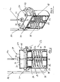
- FIG. 1 Shown are the first embodiment according to Figures 1 to 3, the essential components which form the device 1 for controlling the constant outflow from a liquid container, in particular a rain retention space.
- the rain retention space itself is not illustrated, but this only a flange 2, through which the liquid exits in the direction of arrow 3 when leaving the liquid container.
- the liquid nozzle 2 is embedded in a wall, not shown, of the liquid container and is located in the region of the sole of the container. With the actual flanged ring 4 of the flange 2 facing away from the end of the Flanschstutzens 2 a plate 5 is welded to this, which is provided with a circular opening whose diameter corresponds to the opening diameter 6 of the Flanschstutzens 2.
- the flange 2 and the plate 5 form a structural unit. Parallel to the plate 5 and at a slight distance to this another plate 7 is positioned, which is dimensioned according to the plate 5, thus having a corresponding opening.
- This plate 7 is welded to a larger bearing plate 8, which is positioned vertically as well as the two plates 5 and 7 and with a horizontal lower base plate 9 is welded.
- the bearing plate 8 is provided with an opening aligned in the plates 5 and 7 opening. Escaping fluid thus passes through the flange 2 and the openings in the two plates 5 and 7 and the opening in the bearing plate 8 from the liquid container.
- the gap between the two plates 5 and 7 serves to receive a plate-shaped aperture 10.
- a plate-shaped aperture 10 This is, for example, as shown in Figure 1, designed bottom v-shaped.
- the control opening of the device 1 is designated by the reference numeral 11.
- the aperture 10 In the fully lowered position of the diaphragm 10, as illustrated in FIGS. 1 and 2, only a small passage cross-section for the fluid is formed between the V-shaped limbs of the diaphragm 10.
- the aperture 10 When completely raised position, the aperture 10, the opening diameter 6 largely free, resulting in a large control opening 11 results.
- the two plates 5 and 7 thus serve to guide the aperture 10 in the outflow of the liquid.
- the panel 10 is thus rectilinear and vertically movable.
- the diaphragm 10 is connected centrally to a suspension 13.
- This is also plate-shaped and has a vertically extending, elongated passage slot 14.
- the suspension 13 takes in the region of the diaphragm 10 facing away from the upper end of a horizontally oriented pin 15.
- a vertically oriented bar 16 is connected, which is also provided with a vertically oriented passage slot 17.
- a corresponding bar 18 with passage slot 19 is connected in the region of its upper end by means of a spacer pin 20 with the bar 16.
- a spacer pin 21 connects the two strips 16 and 18 in the region of its lower end. It passes through, starting from the bar 18, first the passage slot 14 of the suspension 13 and then a bearing bore of a control disk 22 which is freely rotatable relative to the spacer pin 21.
- the control disk 22 is formed as a circular disk.
- the shape of the passage slot 23 can be made individual according to the particular requirements for controlling the constant outflow, as can be seen from the one end region of the passage slot 23 as shown in FIG.
- the additionally illustrated there in the outer region of the control disk 22 arranged circular holes 24 are provided solely for weight saving reasons.
- the bearing plate 8 has, in addition to the two plates 5 and 7, a recess, in the region of which a hydrostatic converter 27 is arranged. This thus has the function of a function of the fluid pressure in the liquid container form variable element.
- the transducer 27 or pressure transducer has a cylinder 28 and a sealingly guided in this piston 29. This is associated with a rolling diaphragm 30.
- the converter 27 is divided into an upper cylinder space 31 and a lower cylinder space 32 by means of the piston 29 and the rolling diaphragm 30, respectively.
- the upper cylinder chamber 31 is provided in the region of its upper end wall 33 with two openings 34, so that the liquid in the upper cylinder chamber 31 of the liquid container acts with the hydrostatic pressure on the rolling diaphragm 30.
- the lower cylinder chamber 32 a plurality of coil springs 35 are arranged, which are supported on a lower end wall 36 and the piston 29. The ends of the springs 35 are guided in tube lugs 37, which are connected to the end wall 33 and the piston 29.
- the lower cylinder chamber 32 is closed, it has only one lateral opening 38, in the region of which a line 39 is connected laterally over the cylinder 28. This line is an air line, it is at atmospheric pressure or can be externally pressurized.
- a piston rod 40 is centrally mounted and firmly connected thereto.
- the piston rod 40 protrudes partially into the lower cylinder space 32 and passes through the upper cylinder space 31. It protrudes through an opening in the end wall 33 and is led out upwards.
- An outside of the converter 27 arranged, connected to the piston rod 40 and adjustable on this stop 41 serves to limit the movement of the piston rod 40 during retraction of the piston 29th
- the hydrostatic converter 27 is placed in the region of its end wall 36 on the base plate 9 and fastened thereto.
- the piston rod 40 is positioned at a small distance, parallel to the bearing plate 8 and extends vertically.
- a clamp 42 is connected, by means of which a belt 43, in particular a toothed belt is clamped.
- This forms a transmission means, which converts the linear movement of the piston rod 40 in a rotational movement of the control disk 22.
- This transmission means is designed as the self-contained, deflected cable in the manner of a belt.
- the belt 43 is guided around two vertically aligned, horizontal axes rotatable rollers 44 which are mounted in the bearing plate 8. Of these, the belt 43 is also formed around the gear formed as a roller, not shown in detail, which is arranged concentrically to the bore 25 with the control disk 22, out.
- Figures 1 and 2 illustrates the bezel in its fully lowered position
- the other embodiment of Figures 4 and 5 shows a modified apparatus in which the bezel is in its fully raised position.
- the structure of this device is basically the same as that of Figures 1 to 3 and 6, 7.
- Parts of the embodiment according to Figures 4 and 5, with those of the other embodiment according to Figures 1 to 3, 6 and 7 in function or Structure match, are designated for simplicity with the same reference numerals.
- the deviations of the embodiment of Figures 4 and 5 to the other embodiment are as follows.
- the vertical movement of the piston rod 40 is transmitted to the end of a double lever 45, which is pivotable about an axis 46. That the Axis associated pivot bearing is connected to the bearing plate 8.
- the piston rod 40 facing away from the end of the lever 45 takes pivotally, with clearance compensation in the longitudinal direction of the lever 45, a rack, not shown, which is mounted vertically movable in the bearing plate 8. With this rack also meshes a gear, not shown, which is concentric with the bore 25 of the control disk 22 is connected thereto. In this way, the rectilinear movement of the piston rod 40 is translated into the rotational movement of the control disk 22.
- the suspension 13 is designed as a triple-angled component, which consequently has no through slot 14, but only in the region of the end which faces away from the diaphragm 10, the pin 15 which engages in the through slot 23 of the control disk 22.
- the pin 15 engages a rope, which, initially oriented vertically to the upper spacer pin 20 deflected and guided horizontally from there to the side.
- the cable 47 is then deflected about a bearing plate 8 rotatably mounted roller 48, down and it engages the cable end associated with this region of the rope a weight 49 at.
- the weight of the weight 49 is dimensioned so that it substantially corresponds to the total weight of the panel 10 and suspension 13, so that these components are held quasi weightless in the guides 12.
- the diaphragm 10 can be raised and lowered with the least expenditure of force by turning the control disk 22.
- the control edge 55 of this panel 10 is formed substantially straight and arranged horizontally.
- the rolling diaphragm 30 has the function of keeping the frictional resistance between the cylinder 28 and the piston 29 as low as possible.
- the rolling diaphragm 30 is on the one hand connected to the cylinder inner wall on the other hand with the piston. Upon movement of the piston 29 in the cylinder 28, the rolling diaphragm 30 is more or less invaginated. It reliably seals the area between the piston and the cylinder.
- Figures 8 and 9 illustrate a modified design of the hydrostatic transducer 27. Parts which correspond in construction or function to those according to the embodiment of the transducer of Figures 6 and 7 are indicated by the same reference numerals for the sake of simplicity. The deviations in the embodiment of Figures 8 and 9 are as follows:
- the liquid enters the converter from below, thus through the located in the region of the lower end wall 36 openings 34. Illustrated is the converter 27 in the unpressurized position.
- the piston 29 is located near the end wall 36.
- the rolling diaphragm 30 is clamped with its piston 29 remote region between the two flanges 50 and 51 of the cylinder parts 52 and 53.
- Several helical compression springs 35 are supported on the piston 29 and the upper end wall 33. Not illustrated is the cooperating with the upper cylinder chamber 31 line 39th
- Figures 10 to 14 show a device for maintaining a constant outflow of the liquid from a building 56 with upper water 57 and underwater 58.
- the respective liquid level of upper water 57 and underwater 58 is illustrated by the reference numerals 59 and 60, respectively.
- the structure 56 accommodates the device according to the invention, as described for the embodiments according to FIGS. 1 to 9.
- the openings 34 of the hydrostatic converter 27 are arranged on the underside thereof.
- the pressure inlet opening is designated by the reference numeral 61.
- Underwater a corresponding hydrostatic converter 27 is arranged.
- the line 39 connects the two hydrostatic converters 27.
- the pressure inlet opening of the underwater-side hydrostatic converter 27 is likewise designated by the reference numeral 61.
- FIGS. 13 and 14 illustrate the situation of normal operation. From the upper water, the liquid exits into the underwater, so that the liquid levels set 59 and 60.
- the underwater converter 27 does not detect an increased pressure. Accordingly, the aperture 10 is in the control position, the constant amount of liquid per unit of time Q from can flow freely through the defined control opening, as it results from the illustration of Figure 11.
- the situation of backflow is illustrated in FIGS. 13 and 14.
- the increased by backflow fluid level 60 in the underwater 58 causes an increased pressure increase from the line 39 due to the activation of the hydrostatic converter 27 of the underwater. Because of this installed in the underwater pressure transducer 58 - hydrostatic converter - the installed in the upper water 57 pressure transducer - hydrostatic converter 27 - undergoes an inverse function, so that Q can be kept constant from .
- FIGS. 15 and 16 illustrate a device which is extended over that of Figures 10 to 14 in that with this additionally a relocation elimination is possible.
- the hydrostatic converter 27 assigned to the upper water 57 is arranged in a bulkhead container 62, which has the function of a regulator housing.
- This bulkhead container 62 is provided with an outlet opening 63, which corresponds to the control opening 11, further comprising an inlet opening 64, which is arranged on the side facing away from the outlet opening 63 of the bulkhead container 62 and designed according to the outlet opening 63.
- the outlet opening 63 is associated with the aperture 10 described for the device according to the invention.
- the inlet opening 64 is another aperture 65 assigned, which is guided according to the aperture 10 and is controlled.
- the diaphragms 10 and 65 are controlled via the arranged inside the bulkhead container 62 hydrostatic converter 27 in the manner described for the device according to the invention, but independently controlled. For the sake of simplicity, only the piston rod 40 associated with the hydrostatic converter 27 and the suspension 13 of the respective diaphragm 10 or 65 are illustrated.
- the liquid level 59 in the bulkhead container 62 drops.
- the arranged within the bulkhead container 62 hydrostatic converter 27 determines the concomitant pressure drop and controls the two panels 10 and 65 in the sense of an opening movement. Due to the enlarged control cross-section of the inlet opening 64, the installation is washed away and the device is regulated to normal operation.
Landscapes
- Engineering & Computer Science (AREA)
- General Engineering & Computer Science (AREA)
- Mechanical Engineering (AREA)
- Health & Medical Sciences (AREA)
- Life Sciences & Earth Sciences (AREA)
- Hydrology & Water Resources (AREA)
- Public Health (AREA)
- Water Supply & Treatment (AREA)
- Mechanically-Actuated Valves (AREA)
- Control Of Fluid Pressure (AREA)
Priority Applications (1)
| Application Number | Priority Date | Filing Date | Title |
|---|---|---|---|
| EP20050026696 EP1672132B1 (fr) | 2004-12-08 | 2005-12-07 | Dispositif pour assurer un débit constant d'un réservoir d'une fluide |
Applications Claiming Priority (2)
| Application Number | Priority Date | Filing Date | Title |
|---|---|---|---|
| EP20040029033 EP1669499B1 (fr) | 2004-12-08 | 2004-12-08 | Dispositif pour assurer un débit constant d'un réservoir pour fluide |
| EP20050026696 EP1672132B1 (fr) | 2004-12-08 | 2005-12-07 | Dispositif pour assurer un débit constant d'un réservoir d'une fluide |
Publications (3)
| Publication Number | Publication Date |
|---|---|
| EP1672132A2 true EP1672132A2 (fr) | 2006-06-21 |
| EP1672132A3 EP1672132A3 (fr) | 2007-07-18 |
| EP1672132B1 EP1672132B1 (fr) | 2008-10-15 |
Family
ID=36353969
Family Applications (1)
| Application Number | Title | Priority Date | Filing Date |
|---|---|---|---|
| EP20050026696 Expired - Lifetime EP1672132B1 (fr) | 2004-12-08 | 2005-12-07 | Dispositif pour assurer un débit constant d'un réservoir d'une fluide |
Country Status (1)
| Country | Link |
|---|---|
| EP (1) | EP1672132B1 (fr) |
Cited By (1)
| Publication number | Priority date | Publication date | Assignee | Title |
|---|---|---|---|---|
| EP3109368A1 (fr) | 2015-06-26 | 2016-12-28 | Jörg-Michael Steinhardt | Regulateur de debit d'ecoulement |
Families Citing this family (1)
| Publication number | Priority date | Publication date | Assignee | Title |
|---|---|---|---|---|
| DE102016117216B4 (de) | 2016-09-13 | 2020-03-19 | BIONIK GmbH - Innovative Technik für die Umwelt | Vorrichtung zur Durchflussregelung für Ausläufe in Flüssigkeitsrückhaltebecken |
Citations (7)
| Publication number | Priority date | Publication date | Assignee | Title |
|---|---|---|---|---|
| DE3240902A1 (de) | 1982-11-05 | 1984-05-10 | Lothar Dipl.-Ing. 6204 Taunusstein Steinhardt | Abflussmengenregler |
| DE3418348A1 (de) | 1984-05-17 | 1985-11-21 | Lothar Dipl.-Ing. 6204 Taunusstein Steinhardt | Abflussmengenregler |
| DE3822555A1 (de) | 1988-01-25 | 1989-08-03 | Giehl Klaus Ulrich | Drosselvorrichtung fuer kanalisationsanlagen |
| DE3921766A1 (de) | 1988-07-04 | 1991-01-03 | Giehl Klaus Ulrich | Drosselvorrichtung |
| FR2675562A1 (fr) | 1991-04-17 | 1992-10-23 | Itera Sa | Vanne de regulation de debit d'eau dans un reseau d'assainissement et concue de maniere a assurer une chasse hydraulique de nettoyage du reseau aval pendant la vidange du reseau amont. |
| EP0707254A2 (fr) | 1994-10-11 | 1996-04-17 | Lothar Dipl.-Ing. Steinhardt | Dispositif pour régler un débouché invariable sur un réservoir à liquides |
| DE29920430U1 (de) | 1999-11-22 | 2000-02-24 | Giehl, Klaus Ulrich, 57629 Heimborn | Drosselvorrichtung |
Family Cites Families (1)
| Publication number | Priority date | Publication date | Assignee | Title |
|---|---|---|---|---|
| DE3914703A1 (de) * | 1989-05-04 | 1990-11-08 | Steinhardt Lothar | Abflussmengenregler |
-
2005
- 2005-12-07 EP EP20050026696 patent/EP1672132B1/fr not_active Expired - Lifetime
Patent Citations (7)
| Publication number | Priority date | Publication date | Assignee | Title |
|---|---|---|---|---|
| DE3240902A1 (de) | 1982-11-05 | 1984-05-10 | Lothar Dipl.-Ing. 6204 Taunusstein Steinhardt | Abflussmengenregler |
| DE3418348A1 (de) | 1984-05-17 | 1985-11-21 | Lothar Dipl.-Ing. 6204 Taunusstein Steinhardt | Abflussmengenregler |
| DE3822555A1 (de) | 1988-01-25 | 1989-08-03 | Giehl Klaus Ulrich | Drosselvorrichtung fuer kanalisationsanlagen |
| DE3921766A1 (de) | 1988-07-04 | 1991-01-03 | Giehl Klaus Ulrich | Drosselvorrichtung |
| FR2675562A1 (fr) | 1991-04-17 | 1992-10-23 | Itera Sa | Vanne de regulation de debit d'eau dans un reseau d'assainissement et concue de maniere a assurer une chasse hydraulique de nettoyage du reseau aval pendant la vidange du reseau amont. |
| EP0707254A2 (fr) | 1994-10-11 | 1996-04-17 | Lothar Dipl.-Ing. Steinhardt | Dispositif pour régler un débouché invariable sur un réservoir à liquides |
| DE29920430U1 (de) | 1999-11-22 | 2000-02-24 | Giehl, Klaus Ulrich, 57629 Heimborn | Drosselvorrichtung |
Cited By (4)
| Publication number | Priority date | Publication date | Assignee | Title |
|---|---|---|---|---|
| EP3109368A1 (fr) | 2015-06-26 | 2016-12-28 | Jörg-Michael Steinhardt | Regulateur de debit d'ecoulement |
| WO2016206984A1 (fr) | 2015-06-26 | 2016-12-29 | Jörg-Michael Steinhardt | Régulateur de débit de sortie |
| CN107771232A (zh) * | 2015-06-26 | 2018-03-06 | 约尔格-米夏埃尔·施泰因哈特 | 排流量调节器 |
| CN107771232B (zh) * | 2015-06-26 | 2020-06-09 | 水泰和有限公司 | 排流量调节器 |
Also Published As
| Publication number | Publication date |
|---|---|
| EP1672132A3 (fr) | 2007-07-18 |
| EP1672132B1 (fr) | 2008-10-15 |
Similar Documents
| Publication | Publication Date | Title |
|---|---|---|
| EP1669499B1 (fr) | Dispositif pour assurer un débit constant d'un réservoir pour fluide | |
| EP0310595B1 (fr) | Vanne de régulation | |
| DE2754482A1 (de) | Tuerschliesser | |
| DE10324127C5 (de) | Hydraulischer Türantrieb | |
| EP3109368B1 (fr) | Regulateur de debit d'ecoulement | |
| EP0707254B1 (fr) | Dispositif pour régler un débouché invariable sur un réservoir à liquides | |
| EP1672132B1 (fr) | Dispositif pour assurer un débit constant d'un réservoir d'une fluide | |
| DE3912436C2 (de) | Vorrichtung zum Regeln des Abflusses | |
| DE4406815C2 (de) | Pneumatischer Schwenkantrieb | |
| DE3922481A1 (de) | Vorrichtung zur regelung des durchflusses durch kanaele, insbesondere abwasserkanaele | |
| DE2103701C3 (de) | Elektrohydraulische Verstellvorrichtung | |
| EP1431640B1 (fr) | Dispositif de soupape avec une servovanne controlée par un moteur électrique | |
| DE3934530C2 (de) | Hydrostatische Wehreinrichtung | |
| DE2856000A1 (de) | Anlage zur verguetung von blechen | |
| DE10249509A1 (de) | Pneumatischer Stellantrieb | |
| DE4033115C2 (de) | Regelbarer Schwingungsdämpfer für Kraftfahrzeuge | |
| EP2518251A2 (fr) | Ferme-porte | |
| DE102011018736A1 (de) | Untersturzdrehflügeltürbetätiger | |
| EP0108378A1 (fr) | Régulateur d'écoulement d'eaux | |
| DE2721974A1 (de) | Tuerschliesser | |
| DE19524777B4 (de) | Türschließer mit einstellbarer Vorspannung einer Schließerfeder | |
| DE102018006448A1 (de) | Abflussdrossel | |
| DE202008009193U1 (de) | Vorrichtung zur Regulierung der Durchflussmenge einer Aus- bzw. Zulauföffnung eines Ausgleichsbehälters für Flüssigkeiten | |
| DE102016117216B4 (de) | Vorrichtung zur Durchflussregelung für Ausläufe in Flüssigkeitsrückhaltebecken | |
| DE102010041704A1 (de) | Regelventil zur Regelung eines Volumenstromes |
Legal Events
| Date | Code | Title | Description |
|---|---|---|---|
| PUAI | Public reference made under article 153(3) epc to a published international application that has entered the european phase |
Free format text: ORIGINAL CODE: 0009012 |
|
| AK | Designated contracting states |
Kind code of ref document: A2 Designated state(s): AT BE BG CH CY CZ DE DK EE ES FI FR GB GR HU IE IS IT LI LT LU LV MC NL PL PT RO SE SI SK TR |
|
| AX | Request for extension of the european patent |
Extension state: AL BA HR MK YU |
|
| PUAL | Search report despatched |
Free format text: ORIGINAL CODE: 0009013 |
|
| AK | Designated contracting states |
Kind code of ref document: A3 Designated state(s): AT BE BG CH CY CZ DE DK EE ES FI FR GB GR HU IE IS IT LI LT LU LV MC NL PL PT RO SE SI SK TR |
|
| AX | Request for extension of the european patent |
Extension state: AL BA HR MK YU |
|
| 17P | Request for examination filed |
Effective date: 20070821 |
|
| AKX | Designation fees paid |
Designated state(s): AT BE BG CH CY CZ DE DK EE ES FI FR GB GR HU IE IS IT LI LT LU LV MC NL PL PT RO SE SI SK TR |
|
| GRAP | Despatch of communication of intention to grant a patent |
Free format text: ORIGINAL CODE: EPIDOSNIGR1 |
|
| GRAS | Grant fee paid |
Free format text: ORIGINAL CODE: EPIDOSNIGR3 |
|
| GRAA | (expected) grant |
Free format text: ORIGINAL CODE: 0009210 |
|
| AK | Designated contracting states |
Kind code of ref document: B1 Designated state(s): AT BE BG CH CY CZ DE DK EE ES FI FR GB GR HU IE IS IT LI LT LU LV MC NL PL PT RO SE SI SK TR |
|
| REG | Reference to a national code |
Ref country code: CH Ref legal event code: EP Ref country code: GB Ref legal event code: FG4D Free format text: NOT ENGLISH |
|
| REG | Reference to a national code |
Ref country code: IE Ref legal event code: FG4D Free format text: LANGUAGE OF EP DOCUMENT: GERMAN |
|
| REF | Corresponds to: |
Ref document number: 502005005680 Country of ref document: DE Date of ref document: 20081127 Kind code of ref document: P |
|
| REG | Reference to a national code |
Ref country code: CH Ref legal event code: NV Representative=s name: ISLER & PEDRAZZINI AG |
|
| NLV1 | Nl: lapsed or annulled due to failure to fulfill the requirements of art. 29p and 29m of the patents act | ||
| PG25 | Lapsed in a contracting state [announced via postgrant information from national office to epo] |
Ref country code: BG Free format text: LAPSE BECAUSE OF FAILURE TO SUBMIT A TRANSLATION OF THE DESCRIPTION OR TO PAY THE FEE WITHIN THE PRESCRIBED TIME-LIMIT Effective date: 20090115 Ref country code: ES Free format text: LAPSE BECAUSE OF FAILURE TO SUBMIT A TRANSLATION OF THE DESCRIPTION OR TO PAY THE FEE WITHIN THE PRESCRIBED TIME-LIMIT Effective date: 20090126 Ref country code: LT Free format text: LAPSE BECAUSE OF FAILURE TO SUBMIT A TRANSLATION OF THE DESCRIPTION OR TO PAY THE FEE WITHIN THE PRESCRIBED TIME-LIMIT Effective date: 20081015 |
|
| PG25 | Lapsed in a contracting state [announced via postgrant information from national office to epo] |
Ref country code: NL Free format text: LAPSE BECAUSE OF FAILURE TO SUBMIT A TRANSLATION OF THE DESCRIPTION OR TO PAY THE FEE WITHIN THE PRESCRIBED TIME-LIMIT Effective date: 20081015 Ref country code: LV Free format text: LAPSE BECAUSE OF FAILURE TO SUBMIT A TRANSLATION OF THE DESCRIPTION OR TO PAY THE FEE WITHIN THE PRESCRIBED TIME-LIMIT Effective date: 20081015 Ref country code: PT Free format text: LAPSE BECAUSE OF FAILURE TO SUBMIT A TRANSLATION OF THE DESCRIPTION OR TO PAY THE FEE WITHIN THE PRESCRIBED TIME-LIMIT Effective date: 20090316 Ref country code: FI Free format text: LAPSE BECAUSE OF FAILURE TO SUBMIT A TRANSLATION OF THE DESCRIPTION OR TO PAY THE FEE WITHIN THE PRESCRIBED TIME-LIMIT Effective date: 20081015 Ref country code: PL Free format text: LAPSE BECAUSE OF FAILURE TO SUBMIT A TRANSLATION OF THE DESCRIPTION OR TO PAY THE FEE WITHIN THE PRESCRIBED TIME-LIMIT Effective date: 20081015 Ref country code: SI Free format text: LAPSE BECAUSE OF FAILURE TO SUBMIT A TRANSLATION OF THE DESCRIPTION OR TO PAY THE FEE WITHIN THE PRESCRIBED TIME-LIMIT Effective date: 20081015 Ref country code: IS Free format text: LAPSE BECAUSE OF FAILURE TO SUBMIT A TRANSLATION OF THE DESCRIPTION OR TO PAY THE FEE WITHIN THE PRESCRIBED TIME-LIMIT Effective date: 20090215 |
|
| REG | Reference to a national code |
Ref country code: IE Ref legal event code: FD4D |
|
| PG25 | Lapsed in a contracting state [announced via postgrant information from national office to epo] |
Ref country code: EE Free format text: LAPSE BECAUSE OF FAILURE TO SUBMIT A TRANSLATION OF THE DESCRIPTION OR TO PAY THE FEE WITHIN THE PRESCRIBED TIME-LIMIT Effective date: 20081015 Ref country code: DK Free format text: LAPSE BECAUSE OF FAILURE TO SUBMIT A TRANSLATION OF THE DESCRIPTION OR TO PAY THE FEE WITHIN THE PRESCRIBED TIME-LIMIT Effective date: 20081015 Ref country code: RO Free format text: LAPSE BECAUSE OF FAILURE TO SUBMIT A TRANSLATION OF THE DESCRIPTION OR TO PAY THE FEE WITHIN THE PRESCRIBED TIME-LIMIT Effective date: 20081015 Ref country code: IE Free format text: LAPSE BECAUSE OF FAILURE TO SUBMIT A TRANSLATION OF THE DESCRIPTION OR TO PAY THE FEE WITHIN THE PRESCRIBED TIME-LIMIT Effective date: 20081015 Ref country code: MC Free format text: LAPSE BECAUSE OF NON-PAYMENT OF DUE FEES Effective date: 20081231 |
|
| PLBE | No opposition filed within time limit |
Free format text: ORIGINAL CODE: 0009261 |
|
| STAA | Information on the status of an ep patent application or granted ep patent |
Free format text: STATUS: NO OPPOSITION FILED WITHIN TIME LIMIT |
|
| PG25 | Lapsed in a contracting state [announced via postgrant information from national office to epo] |
Ref country code: CZ Free format text: LAPSE BECAUSE OF FAILURE TO SUBMIT A TRANSLATION OF THE DESCRIPTION OR TO PAY THE FEE WITHIN THE PRESCRIBED TIME-LIMIT Effective date: 20081015 Ref country code: SE Free format text: LAPSE BECAUSE OF FAILURE TO SUBMIT A TRANSLATION OF THE DESCRIPTION OR TO PAY THE FEE WITHIN THE PRESCRIBED TIME-LIMIT Effective date: 20090115 Ref country code: IT Free format text: LAPSE BECAUSE OF FAILURE TO SUBMIT A TRANSLATION OF THE DESCRIPTION OR TO PAY THE FEE WITHIN THE PRESCRIBED TIME-LIMIT Effective date: 20081015 |
|
| 26N | No opposition filed |
Effective date: 20090716 |
|
| PG25 | Lapsed in a contracting state [announced via postgrant information from national office to epo] |
Ref country code: SK Free format text: LAPSE BECAUSE OF FAILURE TO SUBMIT A TRANSLATION OF THE DESCRIPTION OR TO PAY THE FEE WITHIN THE PRESCRIBED TIME-LIMIT Effective date: 20081015 |
|
| PG25 | Lapsed in a contracting state [announced via postgrant information from national office to epo] |
Ref country code: LU Free format text: LAPSE BECAUSE OF NON-PAYMENT OF DUE FEES Effective date: 20081207 Ref country code: HU Free format text: LAPSE BECAUSE OF FAILURE TO SUBMIT A TRANSLATION OF THE DESCRIPTION OR TO PAY THE FEE WITHIN THE PRESCRIBED TIME-LIMIT Effective date: 20090416 Ref country code: CY Free format text: LAPSE BECAUSE OF FAILURE TO SUBMIT A TRANSLATION OF THE DESCRIPTION OR TO PAY THE FEE WITHIN THE PRESCRIBED TIME-LIMIT Effective date: 20081015 |
|
| PG25 | Lapsed in a contracting state [announced via postgrant information from national office to epo] |
Ref country code: TR Free format text: LAPSE BECAUSE OF FAILURE TO SUBMIT A TRANSLATION OF THE DESCRIPTION OR TO PAY THE FEE WITHIN THE PRESCRIBED TIME-LIMIT Effective date: 20081015 |
|
| PG25 | Lapsed in a contracting state [announced via postgrant information from national office to epo] |
Ref country code: GR Free format text: LAPSE BECAUSE OF FAILURE TO SUBMIT A TRANSLATION OF THE DESCRIPTION OR TO PAY THE FEE WITHIN THE PRESCRIBED TIME-LIMIT Effective date: 20090116 |
|
| PGFP | Annual fee paid to national office [announced via postgrant information from national office to epo] |
Ref country code: AT Payment date: 20101214 Year of fee payment: 6 Ref country code: FR Payment date: 20110104 Year of fee payment: 6 |
|
| PGFP | Annual fee paid to national office [announced via postgrant information from national office to epo] |
Ref country code: CH Payment date: 20101224 Year of fee payment: 6 |
|
| PGFP | Annual fee paid to national office [announced via postgrant information from national office to epo] |
Ref country code: GB Payment date: 20101221 Year of fee payment: 6 |
|
| PGFP | Annual fee paid to national office [announced via postgrant information from national office to epo] |
Ref country code: BE Payment date: 20110124 Year of fee payment: 6 |
|
| BERE | Be: lapsed |
Owner name: STEINHARDT G.M.B.H. Effective date: 20111231 |
|
| REG | Reference to a national code |
Ref country code: CH Ref legal event code: PL |
|
| GBPC | Gb: european patent ceased through non-payment of renewal fee |
Effective date: 20111207 |
|
| REG | Reference to a national code |
Ref country code: FR Ref legal event code: ST Effective date: 20120831 |
|
| PG25 | Lapsed in a contracting state [announced via postgrant information from national office to epo] |
Ref country code: LI Free format text: LAPSE BECAUSE OF NON-PAYMENT OF DUE FEES Effective date: 20111231 Ref country code: GB Free format text: LAPSE BECAUSE OF NON-PAYMENT OF DUE FEES Effective date: 20111207 Ref country code: CH Free format text: LAPSE BECAUSE OF NON-PAYMENT OF DUE FEES Effective date: 20111231 Ref country code: BE Free format text: LAPSE BECAUSE OF NON-PAYMENT OF DUE FEES Effective date: 20111231 |
|
| REG | Reference to a national code |
Ref country code: AT Ref legal event code: MM01 Ref document number: 411431 Country of ref document: AT Kind code of ref document: T Effective date: 20111207 |
|
| PG25 | Lapsed in a contracting state [announced via postgrant information from national office to epo] |
Ref country code: AT Free format text: LAPSE BECAUSE OF NON-PAYMENT OF DUE FEES Effective date: 20111207 |
|
| PG25 | Lapsed in a contracting state [announced via postgrant information from national office to epo] |
Ref country code: FR Free format text: LAPSE BECAUSE OF NON-PAYMENT OF DUE FEES Effective date: 20120102 |
|
| PGFP | Annual fee paid to national office [announced via postgrant information from national office to epo] |
Ref country code: DE Payment date: 20220217 Year of fee payment: 17 |
|
| REG | Reference to a national code |
Ref country code: DE Ref legal event code: R119 Ref document number: 502005005680 Country of ref document: DE |
|
| PG25 | Lapsed in a contracting state [announced via postgrant information from national office to epo] |
Ref country code: DE Free format text: LAPSE BECAUSE OF NON-PAYMENT OF DUE FEES Effective date: 20230701 |