EP1672155B1 - Verstellbares Scharnier für Türen und Fenster - Google Patents
Verstellbares Scharnier für Türen und Fenster Download PDFInfo
- Publication number
- EP1672155B1 EP1672155B1 EP05111804A EP05111804A EP1672155B1 EP 1672155 B1 EP1672155 B1 EP 1672155B1 EP 05111804 A EP05111804 A EP 05111804A EP 05111804 A EP05111804 A EP 05111804A EP 1672155 B1 EP1672155 B1 EP 1672155B1
- Authority
- EP
- European Patent Office
- Prior art keywords
- hinge
- pin
- hinge body
- hole
- bush
- Prior art date
- Legal status (The legal status is an assumption and is not a legal conclusion. Google has not performed a legal analysis and makes no representation as to the accuracy of the status listed.)
- Expired - Lifetime
Links
Images


Classifications
-
- E—FIXED CONSTRUCTIONS
- E05—LOCKS; KEYS; WINDOW OR DOOR FITTINGS; SAFES
- E05D—HINGES OR SUSPENSION DEVICES FOR DOORS, WINDOWS OR WINGS
- E05D7/00—Hinges or pivots of special construction
- E05D7/0009—Adjustable hinges
- E05D7/0018—Adjustable hinges at the hinge axis
- E05D7/0045—Adjustable hinges at the hinge axis in a radial direction
- E05D7/0054—Adjustable hinges at the hinge axis in a radial direction by means of eccentric parts
-
- E—FIXED CONSTRUCTIONS
- E05—LOCKS; KEYS; WINDOW OR DOOR FITTINGS; SAFES
- E05D—HINGES OR SUSPENSION DEVICES FOR DOORS, WINDOWS OR WINGS
- E05D5/00—Construction of single parts, e.g. the parts for attachment
- E05D5/02—Parts for attachment, e.g. flaps
- E05D5/0215—Parts for attachment, e.g. flaps for attachment to profile members or the like
- E05D5/0223—Parts for attachment, e.g. flaps for attachment to profile members or the like with parts, e.g. screws, extending through the profile wall or engaging profile grooves
- E05D5/023—Parts for attachment, e.g. flaps for attachment to profile members or the like with parts, e.g. screws, extending through the profile wall or engaging profile grooves with parts extending through the profile wall
-
- E—FIXED CONSTRUCTIONS
- E05—LOCKS; KEYS; WINDOW OR DOOR FITTINGS; SAFES
- E05D—HINGES OR SUSPENSION DEVICES FOR DOORS, WINDOWS OR WINGS
- E05D5/00—Construction of single parts, e.g. the parts for attachment
- E05D5/02—Parts for attachment, e.g. flaps
- E05D5/06—Bent flaps
-
- E—FIXED CONSTRUCTIONS
- E05—LOCKS; KEYS; WINDOW OR DOOR FITTINGS; SAFES
- E05D—HINGES OR SUSPENSION DEVICES FOR DOORS, WINDOWS OR WINGS
- E05D5/00—Construction of single parts, e.g. the parts for attachment
- E05D5/10—Pins, sockets or sleeves; Removable pins
- E05D2005/102—Pins
- E05D2005/106—Pins with non-cylindrical portions
-
- E—FIXED CONSTRUCTIONS
- E05—LOCKS; KEYS; WINDOW OR DOOR FITTINGS; SAFES
- E05Y—INDEXING SCHEME ASSOCIATED WITH SUBCLASSES E05D AND E05F, RELATING TO CONSTRUCTION ELEMENTS, ELECTRIC CONTROL, POWER SUPPLY, POWER SIGNAL OR TRANSMISSION, USER INTERFACES, MOUNTING OR COUPLING, DETAILS, ACCESSORIES, AUXILIARY OPERATIONS NOT OTHERWISE PROVIDED FOR, APPLICATION THEREOF
- E05Y2900/00—Application of doors, windows, wings or fittings thereof
- E05Y2900/10—Application of doors, windows, wings or fittings thereof for buildings or parts thereof
- E05Y2900/13—Type of wing
- E05Y2900/132—Doors
-
- E—FIXED CONSTRUCTIONS
- E05—LOCKS; KEYS; WINDOW OR DOOR FITTINGS; SAFES
- E05Y—INDEXING SCHEME ASSOCIATED WITH SUBCLASSES E05D AND E05F, RELATING TO CONSTRUCTION ELEMENTS, ELECTRIC CONTROL, POWER SUPPLY, POWER SIGNAL OR TRANSMISSION, USER INTERFACES, MOUNTING OR COUPLING, DETAILS, ACCESSORIES, AUXILIARY OPERATIONS NOT OTHERWISE PROVIDED FOR, APPLICATION THEREOF
- E05Y2900/00—Application of doors, windows, wings or fittings thereof
- E05Y2900/10—Application of doors, windows, wings or fittings thereof for buildings or parts thereof
- E05Y2900/13—Type of wing
- E05Y2900/148—Windows
Definitions
- the present invention relates to an adjustable hinge for doors and windows, in particular doors and windows with frames made of metal, PVC, wood, wood and metal, etc.
- hinges consist of two hinge bodies joined by a hinge pin inserted in respective cylindrical housings in the hinge bodies.
- hinges of this kind lie in the shape of the two hinge bodies and the fact that the hinge bodies are mounted on the "face" of the respective parts of the fixed and mobile door or window frames.
- one hinge body designed to be applied to the fixed frame, consists of a hollow element without a flap (and preferably forming a U-shaped section) and has a flat outer surface designed to abut against the face of the fixed frame and to be fastened to the latter by one or more screws.
- the screws pass through the element transversally in respective housings made in the element itself.
- the screws remain housed in the first hinge body thanks to countersunk recesses made on the inside surface of the cylindrical housing in such a way that the screws do not interfere with the pin when it is inserted into the housing.
- the second hinge body has a bush positioned between pin and housing and a shaped flap with a free end that defines a tubular portion that matches and couples with a profile of a tubular chamber in the mobile frame (of the door or window).
- This tubular portion is also engaged by screws that pass through it transversally in respective housings made in the portion itself in such a way as to fasten it securely to (the face of) the door or window frame profile on the inside of the frame itself.
- hinges of this kind cannot be adjusted in a vertical axis (axis of rotation Z), an axis perpendicular to the vertical plane of the fixed door or window frame (axis Y, and also known as "compression” in the jargon of the trade) and an axis parallel to the vertical plane of the door or window (axis X).
- Adjustable hinges of this kind are known in the prior art, for example from GB 2 393 480 , FR 2 031 722 , EP 1 405 975 , GB 720 959 .
- Prior art document FR 2031722 discloses a frame for door or windows, comprising a hinge having a pin with grooved surface and an intermediate element interposed between the grooved surface of the pin and a mobile frame of the door or window.
- the intermediate element is eccentric, in order to provide an adjustable eccentric pivotal axis of the mobile frame.
- an adjustable hinge for doors comprising an eccentric pin received in a fixed frame and in a mobile frame, and also comprising a screwed bolt able to fix the position of the pin in respect of the mobile frame.
- the eccentric pin make possible to adjust the position of the pivotal axis of the mobile frame. None of the cited documents shows an easy adjustment of the position the cited pivotal axis.
- an adjustable hinge for doors and windows is achieved by an adjustable hinge for doors and windows, according to one or more of the appended claims.
- the hinge according to the invention labelled 1 in its entirety, is used in particular for doors and windows with frames made of metal, PVC, wood, wood and metal, etc.
- the hinge 1 is applied to light-weight doors and windows that can be mounted on the upright or fixed frame and to the sash or mobile frame using hinges of the type known as "face-mounted hinges".
- the hinge 1 may essentially comprise:
- hinge 1 is also characterised at least by:
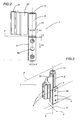
- these actuating means 13 also constitute means for adjusting the hinge 1 in a vertical axis Z, that is to say, lengthways along the pin 8, so as to vary the relative axial distance D between the first hinge body 2 and the second hinge body 5.
- the hinge 1 also comprises a bush 11, defining anti-friction means, positioned between the hole 10 in the second hinge body 5 and the respective second portion 8b of the pin 8 housed in it.
- the hinge 1 can be adjusted in all three axes X, Y, Z without having to remove any of the hinge components.
- the first hinge body consists of a prismatic element 2, with a substantially U-shaped cross section, having a flat outside surface 2a abutting against the fixed frame.
- the first, transversal through housings 3 are made in this prismatic element 2 and are designed to accommodate the first means 4 for fastening the prismatic element 2 itself to the face of the fixed frame.
- the first fastening means 4 may be screws (drawn in dashed line style), that are positioned partly inside the element 2, are attached to the fixed frame, and do not interfere with the hole, 9 which accommodates the pin 8 thanks to countersunk recesses 2v made in the element 2 itself (as clearly shown in Figure 4 ).
- the prismatic element 2 is also fitted with the means 13 for actuating the adjustment means 12.
- the second hinge body consists of cylindrical element 5 having the through hole 10 and a flap 20 designed to be coupled to the mobile frame by a free end of it 21.
- the free end 21 is formed into a tubular shape (the shape depending on the shape of the frame profile) for slidably coupling with a matching profile inside the mobile frame.
- the free end 21 also has the second housings 6 for accommodating the second fastening means 7 (consisting of screws, drawn in dashed line style in Figure 6 ).
- the cylindrical element 5, too, is fastened by screwing the screws 7, from the front and transversally of the shaped free end 21, these screws remaining flush with the surface of the free end 21 itself thanks to the outside countersunk recesses 21v.
- the hole 10 in the cylindrical element 5 accommodates the bush 11 and the second portion 8b of the pin 8 that is offset from the first portion 8a.
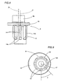
- the adjustment means 12 comprise a plurality of notches 14 or radial protrusions uniformly distributed around the first portion 8a of the pin 8 (see Figures 7 to 9 ) in the vicinity of a circular plate 15 separating the two portions 8a and 8b of the pin 8.
- These radial protrusions 14 can be accommodated in respective radial grooves 16 made at the top end of the first hinge body 8a, inside the hole 9 that houses the pin 8, in such a way that, during use, the pin 8 itself can be turned so that the second portion 8b of the pin 8 moves from one to another of two or more separate, firm adjustment positions: the eccentricity of the second portion 8b of the pin 8 thus makes it possible to vary the position of the second hinge body 5 relative to the first hinge body 2 in the two axes X and Y.
- the radial grooves 14 in the first hinge body 2 extend for the full length of the hole 9 in the first hinge body 2, giving the cross-section of the hole 9 itself the shape of a "star".
- FIG. 8 shows how the radial protrusions 14 extend along the first portion 8a of the pin 8, starting from the circular separating plate 15, for a length at least equal to the maximum variation of the axial distance D between the first and the second hinge bodies 2 and 5 that can be imparted by lifting to adjust the first portion 8a of the pin 8 using the actuating means 13 (described below): thus, the connection between protrusions 14 and grooves 16 is maintained irrespective of variations in the distance D.
- each radial protrusion 14 is positioned, relative to the protrusion 14 before or after it, at an angle ⁇ which, in the non-restricting embodiment illustrated by way of example, is equal to 45°: this enables adjustment to the aforementioned separate positions simultaneously in the axes X and Y by turning the pin 8 at least through the angle ⁇ .
- the angular interval between two radial protrusions 14 may be more or less than 45° depending on the specific adjustment features to be implemented.
- Figures 8 and 9 also show that each of the radial protrusions 14 has an arc-shaped cross section and is bevelled at its free end 14a, opposite the circular plate 15, so that the protrusions 14 match the shape of the first portion 8a of the pin 8 and slide smoothly and securely into place once adjusted.
- one of the radial protrusions labelled 14b in the drawing, has a quadrangular cross section allowing the position of the second portion 8b of the pin 8 to be quickly identified.
- the above mentioned means 13 for actuating the adjustment means 12 comprise a grub screw 13g that is screwed into the hole 9 of the first hinge body 2 at the bottom end of the first hinge body 2.
- the grub screw 13g is inserted from the bottom end of the first hinge body 2 so as to thread the bottom part of the hole 9 (see Figure 4 ) with the star-shaped cross section.
- the grub screw 13g is thus positioned in contact with the bottom end of the first portion 8a of the pin 8 and can be screwed in/out of the hole 9 (see arrows F, Figures 2 and 4 ) in order to:
- the bottom end of the first portion 8a of the pin 8 has a recess 17 for contact with the grub screw 13g: this avoids excessive friction during adjustment of the pin 8.
- the bush 11 has a tooth 18 that protrudes radially from the outside surface of the bush 11, extends for the full length of the bush 11 and can be slotted into a matching radial groove 19 made in the hole 10 in the second hinge body 5 so as to hold the bush 11 firmly inside the hole 10: the bush 11 thus constitutes an anti friction element between the pin 8 and the second hinge body 5 to further facilitate adjustment by the turning of the pin 8.
- a hinge made in this way is applied, in pairs, to the door or window by fastening the first and second hinge bodies 2 and 5 to the fixed frame and to the mobile frame which can then turn relative to each other on the hinge pin 8.
- the installer can check that the mobile frame or sash is correctly positioned relative to the fixed frame, adjusting as necessary in the three axes X, Y and Z by turning the grub screw 13g.
- Lifting the pin 8 by turning the grub screw 13g releases the protrusions 14 from the grooves 16 and allows the installer to turn the pin 8 in either direction in such a way as to adjust the second hinge body 5 relative to the first hinge body 2 in the two axes X and Y by moving it into one of the defined adjustment positions.
- the installer turns the grub screw 13g once again to snap the protrusions 14 back into the grooves 16, thereby locking the pin 8 in the new position.
- the pin 8 may be lowered only partly so as to adapt the position of the mobile frame in height, too; in other words, turning the grub screw 13g also makes it possible to vary the axial distance D between the two hinge bodies 2 and 5.
- a hinge made as described above achieves the aforementioned aims thanks to a combination of extremely simple, easy to use components, that do not require major structural changes to the basic components of the hinge: the solution according to the invention can thus be applied to different types of hinges.
- Adjustment is accurate and sure and can be performed quickly after installing the door or window and saves time and effort because there is no need to remove and refit the door or window.
Landscapes
- Engineering & Computer Science (AREA)
- Mechanical Engineering (AREA)
- Hinges (AREA)
Claims (12)
- Verstellbares Scharnier für Türen und Fenster, wobei das Scharnier (1) von dem Typ ist, der Folgendes beinhaltet:- einen ersten, unteren Scharnierkörper (2) mit ersten Aufnahmen (3) zur Unterbringung von ersten Mitteln (4) zur Befestigung des ersten Scharnierkörpers (2) an einem feststehenden Tür- oder Fensterrahmen;- einen zweiten, oberen Scharnierkörper (5) mit zweiten Aufnahmen (6) zur Unterbringung von zweiten Mitteln (7) zur Befestigung des zweiten Scharnierkörpers (5) an einem beweglichen Tür- oder Fensterrahmen;- einen Scharnierzapfen (8), der in entsprechende Löcher (9, 10) eingeführt werden kann, die in dem ersten Scharnierkörper (2) und dem zweiten Scharnierkörper (5) ausgefertigt sind; wobei der Zapfen (8) einen zweiten Abschnitt (8b) aufweist, der in dem zweiten, oberen Scharnierkörper (5) aufgenommen wird und der versetzt ist im Verhältnis zu einem ersten Abschnitt (8a), der in dem ersten Scharnierkörper (2) aufgenommen wird;- Mittel (12), die auf dem Zapfen (8) ausgebildet sind und zumindest zwischen dem zweiten Abschnitt (8b) des Zapfens (8) und dem zweiten Scharnierkörper (5) derart wirken, dass der zweite Scharnierkörper (5) relativ zu dem ersten Scharnierkörper (2) in einer ersten Achse (X) beziehungsweise in einer zweiten Achse (Y) eingestellt wird, die parallel beziehungsweise perpendikular zu der Tür- oder Fensterebene ausgerichtet sind;- Betätigungsmittel (13), die auf dem ersten Scharnierkörper (2) angeordnet sind, auf den ersten Abschnitt (8a) des Zapfens (8) wirken und dazu dienen, die Einstellmittel (12) freizugeben, so dass der Zapfen (8) bewegt und somit eingestellt werden kann, und die Einstellmittel (12) zu blockieren, so dass der Zapfen (8) in der neuen Position, auf die er eingestellt wurde, festgehalten wird;wobei das Scharnier (1) dadurch gekennzeichnet ist, dass:- die Einstellmittel (12) mehrere Rasten oder radiale Vorsprünge (14) aufweisen, gleichmäßig verteilt um den ersten Abschnitt (8a) des Zapfens (8) in der Nähe einer kreisförmigen Platte (15), welche die zwei Abschnitte (8a, 8b) voneinander trennt; wobei diese radialen Vorsprünge (14) in entsprechenden radialen Nuten (16) aufgenommen werden können, die zumindest am oberen Ende des ersten Scharnierkörpers (2) in dem Loch (9) zur Aufnahme des Zapfens (8) ausgefertigt sind, um zwei oder mehr klar unterscheidbare, stabile Einstellpositionen des zweiten Abschnittes (8b) des Zapfens (8) zu bilden; und dass- die Betätigungsmittel (13) einen Gewindestift (13g) beinhalten, der in das Loch (9) im ersten Scharnierkörper (2) am unteren Ende des ersten Scharnierkörpers (2) eingeschraubt ist; wobei der Gewindestift (13g) in Berührung mit dem unteren Ende des ersten Abschnittes (8a) des Zapfens (8) angeordnet ist, so dass er in das/von dem Loch (9) ein-/ausgeschraubt werden kann, um: den Zapfen (8) entlang der vertikalen Achse (Z) anzuheben, um die radialen Vorsprünge (14) aus den Nuten (16) zu lösen, damit der zweite Abschnitt (8b) zur Einstellung in den zwei Achsen (X, Y) gedreht werden kann; und den Zapfen (8) abzusenken, um ihn in der neuen Position, auf die er eingestellt wurde, zu blockieren.
- Scharnier nach Anspruch 1, dadurch gekennzeichnet, dass es ferner eine Buchse (11) beinhaltet, die zwischen dem Loch (10) in dem zweiten Scharnierkörper (5) und dem entsprechenden zweiten Abschnitt (8b) des darin untergebrachten Zapfens (8) angeordnet ist.
- Scharnier nach Anspruch 1, dadurch gekennzeichnet, dass die Betätigungsmittel (13) ferner Mittel zum Einstellen des Scharniers (1) in einer vertikalen Achse (Z) bilden, das heißt in einer Längsrichtung entlang dem Zapfen (8), um den relativen axialen Abstand (D) zwischen dem ersten Scharnierkörper (2) und dem zweiten Scharnierkörper (5) zu verändern.
- Scharnier nach Anspruch 1, dadurch gekennzeichnet, dass sich die radialen Nuten (16) in dem ersten Scharnierkörper (2) über die gesamte Länge des Lochs (9) in dem ersten Scharnierkörper (2) erstrecken und somit dem Querschnitt des Lochs (9) die Form eines "Sterns" verleihen.
- Scharnier nach Anspruch 1, dadurch gekennzeichnet, dass das untere Ende des ersten Abschnittes (8a) des Zapfens (8) eine Aussparung (17) für den Kontakt mit dem Gewindestift (13g) aufweist.
- Scharnier nach Anspruch 4, dadurch gekennzeichnet, dass sich die radialen Vorsprünge (14) entlang dem ersten Abschnitt (8a) des Zapfens (8), ausgehend von der kreisförmigen Trennplatte (15), über eine Länge erstrecken, die zumindest gleich der maximalen Variation des axialen Abstandes (D) zwischen dem ersten Scharnierkörper (2) und dem zweiten Scharnierkörper (5) ist, der durch das zur Einstellung dienende Anheben des ersten Abschnittes (8a) des Zapfens (8) mittels Gewindestift (13g) definiert wird.
- Scharnier nach den Ansprüchen 4 bis 6, dadurch gekennzeichnet, dass jeder radiale Vorsprung (14) in einem Winkel (α) relativ zu dem vorherigen oder nachfolgenden Vorsprung (14) angeordnet ist.
- Scharnier nach den Ansprüchen 4 bis 7, dadurch gekennzeichnet, dass jeder radiale Vorsprung (14) einen bogenförmigen Querschnitt aufweist und an seinem freien Ende (14a), das der kreisförmigen Platte (15) gegenüber liegt, derart abgeschrägt ist, dass er sich der Form des ersten Abschnittes (8a) des Zapfens (8) anpasst.
- Scharnier nach den Ansprüchen 4 bis 8, dadurch gekennzeichnet, dass einer der radialen Vorsprünge (14b) einen viereckigen Querschnitt aufweist, um einen Bezug zu bilden, der die Position des zweiten Abschnittes (8b) des Zapfens (8) anzeigt.
- Scharnier nach Anspruch 2, dadurch gekennzeichnet, dass die Buchse (11) einen Zahn (18) aufweist, der radial von der Außenoberfläche der Buchse (11) hervorragt, sich über die gesamte Länge der Buchse (11) erstreckt und in eine passende radiale Nut (19) eingeführt werden kann, die in dem Loch (10) in dem zweiten Scharnierkörper (5) angefertigt ist, um die Buchse (11) stabil in dem Loch (10) zu halten und ihre Drehung zu verhindern.
- Scharnier nach Anspruch 1, worin der erste Scharnierkörper aus einem prismatischen Element (2) besteht, das eine flache Außenoberfläche (2a) aufweist, die berührend an dem feststehenden Tür- oder Fensterrahmen anliegt, und in dem die ersten, in Querrichtung durchgehenden Aufnahmen (3) ausgebildet sind, die zur Unterbringung der ersten Mittel (4) zur Befestigung des prismatischen Elementes (2) an der Frontseite des feststehenden Tür- oder Fensterrahmens dienen; wobei das Scharnier dadurch gekennzeichnet ist, dass die Betätigungsmittel (13) auf dem prismatischen Element (2) angeordnet sind.
- Scharnier nach den Ansprüchen 1 und 2, worin der zweite Scharnierkörper aus einem zylindrischen Element (5) besteht, das ein Durchgangsloch (10) und einen Lappen (20) für die Anbringung auf dem beweglichen Tür- oder Fensterrahmen über eines seiner freien Enden (21) aufweist, welches rohrförmig ausgebildet ist, um gleitbar mit einem entsprechenden Profil in dem beweglichen Tür- oder Fensterrahmen gekoppelt werden zu können; wobei in dem geformten Ende (21) die zweiten Aufnahmen (6) zur Unterbringung der zweiten Befestigungsmittel (7) ausgebildet sind; wobei das Scharnier dadurch gekennzeichnet ist, dass die Buchse (11) und der zweite Abschnitt (8b) des Zapfens (8), der gegenüber dem ersten Abschnitt (8a) versetzt ist, in dem zylindrischen Element (5) untergebracht sind.
Applications Claiming Priority (1)
| Application Number | Priority Date | Filing Date | Title |
|---|---|---|---|
| IT000781A ITBO20040781A1 (it) | 2004-12-17 | 2004-12-17 | Cerniera regolabile per infissi |
Publications (2)
| Publication Number | Publication Date |
|---|---|
| EP1672155A1 EP1672155A1 (de) | 2006-06-21 |
| EP1672155B1 true EP1672155B1 (de) | 2010-10-27 |
Family
ID=36011156
Family Applications (1)
| Application Number | Title | Priority Date | Filing Date |
|---|---|---|---|
| EP05111804A Expired - Lifetime EP1672155B1 (de) | 2004-12-17 | 2005-12-07 | Verstellbares Scharnier für Türen und Fenster |
Country Status (4)
| Country | Link |
|---|---|
| EP (1) | EP1672155B1 (de) |
| AT (1) | ATE486186T1 (de) |
| DE (1) | DE602005024354D1 (de) |
| IT (1) | ITBO20040781A1 (de) |
Cited By (1)
| Publication number | Priority date | Publication date | Assignee | Title |
|---|---|---|---|---|
| WO2020076339A1 (en) * | 2018-10-12 | 2020-04-16 | Arconic Inc. | Fine adjustment mechanism for multi-level hinge |
Families Citing this family (41)
| Publication number | Priority date | Publication date | Assignee | Title |
|---|---|---|---|---|
| DE102007025857A1 (de) * | 2007-06-01 | 2008-12-04 | Schüring GmbH & Co. Fenster-Technologie KG | Gelenkband für Türen oder Fenster |
| ITVR20090056A1 (it) * | 2009-04-22 | 2010-10-23 | Roverplastik S P A | Cardine regolabile per il fissaggio al muro di persiane a battente |
| ES2574929T3 (es) * | 2011-10-26 | 2016-06-23 | Josef Hasler | Bisagra con elementos de ajuste y corona de ajuste para dichos elementos de ajuste |
| US9581302B2 (en) | 2012-05-31 | 2017-02-28 | Michael D. Danesh | Recessed lighting module with interchangeable trims |
| US11060705B1 (en) | 2013-07-05 | 2021-07-13 | DMF, Inc. | Compact lighting apparatus with AC to DC converter and integrated electrical connector |
| US10563850B2 (en) | 2015-04-22 | 2020-02-18 | DMF, Inc. | Outer casing for a recessed lighting fixture |
| US11435064B1 (en) | 2013-07-05 | 2022-09-06 | DMF, Inc. | Integrated lighting module |
| US9964266B2 (en) | 2013-07-05 | 2018-05-08 | DMF, Inc. | Unified driver and light source assembly for recessed lighting |
| US10551044B2 (en) | 2015-11-16 | 2020-02-04 | DMF, Inc. | Recessed lighting assembly |
| US10753558B2 (en) | 2013-07-05 | 2020-08-25 | DMF, Inc. | Lighting apparatus and methods |
| US10139059B2 (en) | 2014-02-18 | 2018-11-27 | DMF, Inc. | Adjustable compact recessed lighting assembly with hangar bars |
| US11255497B2 (en) | 2013-07-05 | 2022-02-22 | DMF, Inc. | Adjustable electrical apparatus with hangar bars for installation in a building |
| CA2931588C (en) | 2015-05-29 | 2021-09-14 | DMF, Inc. | Lighting module for recessed lighting systems |
| USD851046S1 (en) | 2015-10-05 | 2019-06-11 | DMF, Inc. | Electrical Junction Box |
| US10288103B2 (en) | 2015-11-30 | 2019-05-14 | Lakeshore Equipment Company | Furniture connector |
| ES2909445T3 (es) * | 2017-03-10 | 2022-05-06 | Thomas Hasler | Bisagra de puerta de tres piezas ajustable en 3 dimensiones |
| US10488000B2 (en) | 2017-06-22 | 2019-11-26 | DMF, Inc. | Thin profile surface mount lighting apparatus |
| USD905327S1 (en) | 2018-05-17 | 2020-12-15 | DMF, Inc. | Light fixture |
| WO2018237294A2 (en) | 2017-06-22 | 2018-12-27 | DMF, Inc. | Thin profile surface mount lighting apparatus |
| US11067231B2 (en) | 2017-08-28 | 2021-07-20 | DMF, Inc. | Alternate junction box and arrangement for lighting apparatus |
| CN111670322B (zh) | 2017-11-28 | 2022-04-26 | Dmf股份有限公司 | 可调整的吊架杆组合件 |
| WO2019133669A1 (en) | 2017-12-27 | 2019-07-04 | DMF, Inc. | Methods and apparatus for adjusting a luminaire |
| USD877957S1 (en) | 2018-05-24 | 2020-03-10 | DMF Inc. | Light fixture |
| WO2019241198A1 (en) | 2018-06-11 | 2019-12-19 | DMF, Inc. | A polymer housing for a recessed lighting system and methods for using same |
| USD903605S1 (en) | 2018-06-12 | 2020-12-01 | DMF, Inc. | Plastic deep electrical junction box |
| WO2020072592A1 (en) | 2018-10-02 | 2020-04-09 | Ver Lighting Llc | A bar hanger assembly with mating telescoping bars |
| USD901398S1 (en) | 2019-01-29 | 2020-11-10 | DMF, Inc. | Plastic deep electrical junction box |
| USD1012864S1 (en) | 2019-01-29 | 2024-01-30 | DMF, Inc. | Portion of a plastic deep electrical junction box |
| USD864877S1 (en) | 2019-01-29 | 2019-10-29 | DMF, Inc. | Plastic deep electrical junction box with a lighting module mounting yoke |
| USD966877S1 (en) | 2019-03-14 | 2022-10-18 | Ver Lighting Llc | Hanger bar for a hanger bar assembly |
| IT201900007554A1 (it) * | 2019-05-30 | 2020-11-30 | Giesse Spa | Cerniera regolabile per infissi. |
| FR3097696B1 (fr) * | 2019-06-24 | 2021-07-09 | Schneider Electric Ind Sas | Armoire électrique avec bloc de conditionnement d’air |
| WO2021051101A1 (en) | 2019-09-12 | 2021-03-18 | DMF, Inc. | Miniature lighting module and lighting fixtures using same |
| CN112647251B (zh) * | 2019-10-12 | 2024-06-21 | 重庆海尔滚筒洗衣机有限公司 | 观察窗门铰链的安装结构及衣物处理设备 |
| KR102299511B1 (ko) * | 2019-12-19 | 2021-09-06 | 주식회사 한화건설 | 손끼임 방지 도어용 안전 장치 |
| CA3124969A1 (en) | 2020-07-16 | 2022-01-16 | DMF, Inc. | Round metal housing for a lighting system |
| CA3124987A1 (en) | 2020-07-17 | 2022-01-17 | DMF, Inc. | Bar hanger assembly with crossmembers and housing assemblies using same |
| CA3124976A1 (en) | 2020-07-17 | 2022-01-17 | DMF, Inc. | Polymer housing for a lighting system and methods for using same |
| USD990030S1 (en) | 2020-07-17 | 2023-06-20 | DMF, Inc. | Housing for a lighting system |
| US11585517B2 (en) | 2020-07-23 | 2023-02-21 | DMF, Inc. | Lighting module having field-replaceable optics, improved cooling, and tool-less mounting features |
| DE102023133582A1 (de) * | 2023-11-30 | 2025-06-05 | Sunshine Vans GmbH | Scharnierelement zur Befestigung an einer Türzarge sowie Scharnier mit einem solchen Scharnierelement |
Family Cites Families (4)
| Publication number | Priority date | Publication date | Assignee | Title |
|---|---|---|---|---|
| GB720959A (en) * | 1953-05-18 | 1954-12-29 | Carl Ludvig Carlstroem | Improvements in hinges |
| FR2031722A5 (de) * | 1969-02-05 | 1970-11-20 | Menuiserie Metal Moderne | |
| GB2393480B (en) * | 2002-09-28 | 2005-10-26 | Window Fab & Fixing Supplies | Adjustable pin hinge |
| EP1405975A1 (de) * | 2002-10-04 | 2004-04-07 | Steinbach & Vollmann GmbH & Co. KG | Einstellbare Türbandanordnung |
-
2004
- 2004-12-17 IT IT000781A patent/ITBO20040781A1/it unknown
-
2005
- 2005-12-07 AT AT05111804T patent/ATE486186T1/de not_active IP Right Cessation
- 2005-12-07 DE DE602005024354T patent/DE602005024354D1/de not_active Expired - Lifetime
- 2005-12-07 EP EP05111804A patent/EP1672155B1/de not_active Expired - Lifetime
Cited By (1)
| Publication number | Priority date | Publication date | Assignee | Title |
|---|---|---|---|---|
| WO2020076339A1 (en) * | 2018-10-12 | 2020-04-16 | Arconic Inc. | Fine adjustment mechanism for multi-level hinge |
Also Published As
| Publication number | Publication date |
|---|---|
| DE602005024354D1 (de) | 2010-12-09 |
| EP1672155A1 (de) | 2006-06-21 |
| ITBO20040781A1 (it) | 2005-03-17 |
| ATE486186T1 (de) | 2010-11-15 |
Similar Documents
| Publication | Publication Date | Title |
|---|---|---|
| EP1672155A1 (de) | Verstellbares Scharnier für Türen und Fenster | |
| EP0992647B1 (de) | Verstellbares Scharnier für Türrahmen | |
| US6484363B1 (en) | Adjustable hinge | |
| US10557297B2 (en) | Multi panel components | |
| GB2376266A (en) | An adjustable carrier hinge | |
| EP3940164B1 (de) | Verbessertes türschienensystem | |
| US20200208451A1 (en) | Device for securing panes of glass for sliding doors | |
| US5722203A (en) | Prehung door installation aid | |
| EP2447453A1 (de) | Schwenkbar einstellbares Scharnier für eine Schwenktafel | |
| AU2021205126A1 (en) | Door Rail System | |
| EP1698752A2 (de) | Ein einstellbares Scharnier für schwere Türe und Fenster | |
| EP1608831A1 (de) | Scharnier | |
| CN102747910A (zh) | 用于门或类似物的铰链 | |
| EP2458122B1 (de) | Scharnier für Türen oder Fenster | |
| BE1028725B1 (nl) | Rozetloze raam- of deurgreep | |
| US10982473B1 (en) | Pivot door assembly | |
| EP2339102B1 (de) | Scharnier für schwere Türen, Fenster und Ähnliches | |
| US7059020B2 (en) | Hinge for doors and similar construction components | |
| EP1598510B1 (de) | Ein verstellbares Türscharnier | |
| EP2085549B1 (de) | Ein Scharnier für Türen oder Fenster | |
| GB2227521A (en) | Adjustable hinges | |
| EP4464862A1 (de) | Scharnier für eine tür oder ein fenster | |
| CN214697375U (zh) | 用于安装门窗的合页 | |
| EP2924211A1 (de) | Verstellbares scharnier für türen oder fenster | |
| EP3976913B1 (de) | Verstellbares scharnier für türen und fenster |
Legal Events
| Date | Code | Title | Description |
|---|---|---|---|
| PUAI | Public reference made under article 153(3) epc to a published international application that has entered the european phase |
Free format text: ORIGINAL CODE: 0009012 |
|
| AK | Designated contracting states |
Kind code of ref document: A1 Designated state(s): AT BE BG CH CY CZ DE DK EE ES FI FR GB GR HU IE IS IT LI LT LU LV MC NL PL PT RO SE SI SK TR |
|
| AX | Request for extension of the european patent |
Extension state: AL BA HR MK YU |
|
| 17P | Request for examination filed |
Effective date: 20060724 |
|
| AKX | Designation fees paid |
Designated state(s): AT BE BG CH CY CZ DE DK EE ES FI FR GB GR HU IE IS IT LI LT LU LV MC NL PL PT RO SE SI SK TR |
|
| 17Q | First examination report despatched |
Effective date: 20071109 |
|
| GRAP | Despatch of communication of intention to grant a patent |
Free format text: ORIGINAL CODE: EPIDOSNIGR1 |
|
| GRAS | Grant fee paid |
Free format text: ORIGINAL CODE: EPIDOSNIGR3 |
|
| GRAA | (expected) grant |
Free format text: ORIGINAL CODE: 0009210 |
|
| AK | Designated contracting states |
Kind code of ref document: B1 Designated state(s): AT BE BG CH CY CZ DE DK EE ES FI FR GB GR HU IE IS IT LI LT LU LV MC NL PL PT RO SE SI SK TR |
|
| REG | Reference to a national code |
Ref country code: GB Ref legal event code: FG4D |
|
| REG | Reference to a national code |
Ref country code: CH Ref legal event code: EP |
|
| REG | Reference to a national code |
Ref country code: IE Ref legal event code: FG4D |
|
| REF | Corresponds to: |
Ref document number: 602005024354 Country of ref document: DE Date of ref document: 20101209 Kind code of ref document: P |
|
| REG | Reference to a national code |
Ref country code: NL Ref legal event code: VDEP Effective date: 20101027 |
|
| LTIE | Lt: invalidation of european patent or patent extension |
Effective date: 20101027 |
|
| PG25 | Lapsed in a contracting state [announced via postgrant information from national office to epo] |
Ref country code: LT Free format text: LAPSE BECAUSE OF FAILURE TO SUBMIT A TRANSLATION OF THE DESCRIPTION OR TO PAY THE FEE WITHIN THE PRESCRIBED TIME-LIMIT Effective date: 20101027 |
|
| PG25 | Lapsed in a contracting state [announced via postgrant information from national office to epo] |
Ref country code: PT Free format text: LAPSE BECAUSE OF FAILURE TO SUBMIT A TRANSLATION OF THE DESCRIPTION OR TO PAY THE FEE WITHIN THE PRESCRIBED TIME-LIMIT Effective date: 20110228 Ref country code: LV Free format text: LAPSE BECAUSE OF FAILURE TO SUBMIT A TRANSLATION OF THE DESCRIPTION OR TO PAY THE FEE WITHIN THE PRESCRIBED TIME-LIMIT Effective date: 20101027 Ref country code: AT Free format text: LAPSE BECAUSE OF FAILURE TO SUBMIT A TRANSLATION OF THE DESCRIPTION OR TO PAY THE FEE WITHIN THE PRESCRIBED TIME-LIMIT Effective date: 20101027 Ref country code: IS Free format text: LAPSE BECAUSE OF FAILURE TO SUBMIT A TRANSLATION OF THE DESCRIPTION OR TO PAY THE FEE WITHIN THE PRESCRIBED TIME-LIMIT Effective date: 20110227 Ref country code: SE Free format text: LAPSE BECAUSE OF FAILURE TO SUBMIT A TRANSLATION OF THE DESCRIPTION OR TO PAY THE FEE WITHIN THE PRESCRIBED TIME-LIMIT Effective date: 20101027 Ref country code: SI Free format text: LAPSE BECAUSE OF FAILURE TO SUBMIT A TRANSLATION OF THE DESCRIPTION OR TO PAY THE FEE WITHIN THE PRESCRIBED TIME-LIMIT Effective date: 20101027 Ref country code: BG Free format text: LAPSE BECAUSE OF FAILURE TO SUBMIT A TRANSLATION OF THE DESCRIPTION OR TO PAY THE FEE WITHIN THE PRESCRIBED TIME-LIMIT Effective date: 20110127 Ref country code: FI Free format text: LAPSE BECAUSE OF FAILURE TO SUBMIT A TRANSLATION OF THE DESCRIPTION OR TO PAY THE FEE WITHIN THE PRESCRIBED TIME-LIMIT Effective date: 20101027 Ref country code: NL Free format text: LAPSE BECAUSE OF FAILURE TO SUBMIT A TRANSLATION OF THE DESCRIPTION OR TO PAY THE FEE WITHIN THE PRESCRIBED TIME-LIMIT Effective date: 20101027 |
|
| PG25 | Lapsed in a contracting state [announced via postgrant information from national office to epo] |
Ref country code: BE Free format text: LAPSE BECAUSE OF FAILURE TO SUBMIT A TRANSLATION OF THE DESCRIPTION OR TO PAY THE FEE WITHIN THE PRESCRIBED TIME-LIMIT Effective date: 20101027 Ref country code: GR Free format text: LAPSE BECAUSE OF FAILURE TO SUBMIT A TRANSLATION OF THE DESCRIPTION OR TO PAY THE FEE WITHIN THE PRESCRIBED TIME-LIMIT Effective date: 20110128 |
|
| PG25 | Lapsed in a contracting state [announced via postgrant information from national office to epo] |
Ref country code: CZ Free format text: LAPSE BECAUSE OF FAILURE TO SUBMIT A TRANSLATION OF THE DESCRIPTION OR TO PAY THE FEE WITHIN THE PRESCRIBED TIME-LIMIT Effective date: 20101027 Ref country code: EE Free format text: LAPSE BECAUSE OF FAILURE TO SUBMIT A TRANSLATION OF THE DESCRIPTION OR TO PAY THE FEE WITHIN THE PRESCRIBED TIME-LIMIT Effective date: 20101027 Ref country code: MC Free format text: LAPSE BECAUSE OF NON-PAYMENT OF DUE FEES Effective date: 20101231 Ref country code: ES Free format text: LAPSE BECAUSE OF FAILURE TO SUBMIT A TRANSLATION OF THE DESCRIPTION OR TO PAY THE FEE WITHIN THE PRESCRIBED TIME-LIMIT Effective date: 20110207 |
|
| REG | Reference to a national code |
Ref country code: CH Ref legal event code: PL |
|
| PG25 | Lapsed in a contracting state [announced via postgrant information from national office to epo] |
Ref country code: SK Free format text: LAPSE BECAUSE OF FAILURE TO SUBMIT A TRANSLATION OF THE DESCRIPTION OR TO PAY THE FEE WITHIN THE PRESCRIBED TIME-LIMIT Effective date: 20101027 Ref country code: DK Free format text: LAPSE BECAUSE OF FAILURE TO SUBMIT A TRANSLATION OF THE DESCRIPTION OR TO PAY THE FEE WITHIN THE PRESCRIBED TIME-LIMIT Effective date: 20101027 Ref country code: RO Free format text: LAPSE BECAUSE OF FAILURE TO SUBMIT A TRANSLATION OF THE DESCRIPTION OR TO PAY THE FEE WITHIN THE PRESCRIBED TIME-LIMIT Effective date: 20101027 Ref country code: PL Free format text: LAPSE BECAUSE OF FAILURE TO SUBMIT A TRANSLATION OF THE DESCRIPTION OR TO PAY THE FEE WITHIN THE PRESCRIBED TIME-LIMIT Effective date: 20101027 |
|
| PLBE | No opposition filed within time limit |
Free format text: ORIGINAL CODE: 0009261 |
|
| STAA | Information on the status of an ep patent application or granted ep patent |
Free format text: STATUS: NO OPPOSITION FILED WITHIN TIME LIMIT |
|
| REG | Reference to a national code |
Ref country code: FR Ref legal event code: ST Effective date: 20110831 |
|
| GBPC | Gb: european patent ceased through non-payment of renewal fee |
Effective date: 20110127 |
|
| 26N | No opposition filed |
Effective date: 20110728 |
|
| PG25 | Lapsed in a contracting state [announced via postgrant information from national office to epo] |
Ref country code: CH Free format text: LAPSE BECAUSE OF NON-PAYMENT OF DUE FEES Effective date: 20101231 Ref country code: FR Free format text: LAPSE BECAUSE OF NON-PAYMENT OF DUE FEES Effective date: 20110103 Ref country code: LI Free format text: LAPSE BECAUSE OF NON-PAYMENT OF DUE FEES Effective date: 20101231 Ref country code: IE Free format text: LAPSE BECAUSE OF NON-PAYMENT OF DUE FEES Effective date: 20101207 |
|
| REG | Reference to a national code |
Ref country code: DE Ref legal event code: R097 Ref document number: 602005024354 Country of ref document: DE Effective date: 20110728 |
|
| PG25 | Lapsed in a contracting state [announced via postgrant information from national office to epo] |
Ref country code: GB Free format text: LAPSE BECAUSE OF NON-PAYMENT OF DUE FEES Effective date: 20110127 |
|
| PG25 | Lapsed in a contracting state [announced via postgrant information from national office to epo] |
Ref country code: CY Free format text: LAPSE BECAUSE OF FAILURE TO SUBMIT A TRANSLATION OF THE DESCRIPTION OR TO PAY THE FEE WITHIN THE PRESCRIBED TIME-LIMIT Effective date: 20101027 |
|
| PG25 | Lapsed in a contracting state [announced via postgrant information from national office to epo] |
Ref country code: HU Free format text: LAPSE BECAUSE OF FAILURE TO SUBMIT A TRANSLATION OF THE DESCRIPTION OR TO PAY THE FEE WITHIN THE PRESCRIBED TIME-LIMIT Effective date: 20110428 Ref country code: LU Free format text: LAPSE BECAUSE OF NON-PAYMENT OF DUE FEES Effective date: 20101207 |
|
| PG25 | Lapsed in a contracting state [announced via postgrant information from national office to epo] |
Ref country code: TR Free format text: LAPSE BECAUSE OF FAILURE TO SUBMIT A TRANSLATION OF THE DESCRIPTION OR TO PAY THE FEE WITHIN THE PRESCRIBED TIME-LIMIT Effective date: 20101027 |
|
| PGFP | Annual fee paid to national office [announced via postgrant information from national office to epo] |
Ref country code: IT Payment date: 20221230 Year of fee payment: 18 Ref country code: DE Payment date: 20221227 Year of fee payment: 18 |
|
| P01 | Opt-out of the competence of the unified patent court (upc) registered |
Effective date: 20230506 |
|
| REG | Reference to a national code |
Ref country code: DE Ref legal event code: R119 Ref document number: 602005024354 Country of ref document: DE |
|
| PG25 | Lapsed in a contracting state [announced via postgrant information from national office to epo] |
Ref country code: DE Free format text: LAPSE BECAUSE OF NON-PAYMENT OF DUE FEES Effective date: 20240702 |
|
| PG25 | Lapsed in a contracting state [announced via postgrant information from national office to epo] |
Ref country code: DE Free format text: LAPSE BECAUSE OF NON-PAYMENT OF DUE FEES Effective date: 20240702 |
|
| PG25 | Lapsed in a contracting state [announced via postgrant information from national office to epo] |
Ref country code: IT Free format text: LAPSE BECAUSE OF NON-PAYMENT OF DUE FEES Effective date: 20231207 |