EP1672185A1 - Nockenwellenzeitsteuerungseinrichtung mit räumlich entfertem Kontrollsystem - Google Patents
Nockenwellenzeitsteuerungseinrichtung mit räumlich entfertem Kontrollsystem Download PDFInfo
- Publication number
- EP1672185A1 EP1672185A1 EP05025536A EP05025536A EP1672185A1 EP 1672185 A1 EP1672185 A1 EP 1672185A1 EP 05025536 A EP05025536 A EP 05025536A EP 05025536 A EP05025536 A EP 05025536A EP 1672185 A1 EP1672185 A1 EP 1672185A1
- Authority
- EP
- European Patent Office
- Prior art keywords
- line
- camshaft
- retard
- advance
- cam timing
- Prior art date
- Legal status (The legal status is an assumption and is not a legal conclusion. Google has not performed a legal analysis and makes no representation as to the accuracy of the status listed.)
- Granted
Links
- 239000012530 fluid Substances 0.000 claims abstract description 26
- RDYMFSUJUZBWLH-UHFFFAOYSA-N endosulfan Chemical compound C12COS(=O)OCC2C2(Cl)C(Cl)=C(Cl)C1(Cl)C2(Cl)Cl RDYMFSUJUZBWLH-UHFFFAOYSA-N 0.000 claims abstract description 25
- 238000002485 combustion reaction Methods 0.000 claims abstract description 4
- 229910000831 Steel Inorganic materials 0.000 claims description 5
- 239000010959 steel Substances 0.000 claims description 5
- 239000000463 material Substances 0.000 claims description 4
- 230000000903 blocking effect Effects 0.000 claims description 2
- XEEYBQQBJWHFJM-UHFFFAOYSA-N Iron Chemical compound [Fe] XEEYBQQBJWHFJM-UHFFFAOYSA-N 0.000 description 4
- XAGFODPZIPBFFR-UHFFFAOYSA-N aluminium Chemical compound [Al] XAGFODPZIPBFFR-UHFFFAOYSA-N 0.000 description 3
- 229910052782 aluminium Inorganic materials 0.000 description 3
- 229910052742 iron Inorganic materials 0.000 description 2
- 230000007246 mechanism Effects 0.000 description 2
- 238000004904 shortening Methods 0.000 description 1
Images



Classifications
-
- F—MECHANICAL ENGINEERING; LIGHTING; HEATING; WEAPONS; BLASTING
- F01—MACHINES OR ENGINES IN GENERAL; ENGINE PLANTS IN GENERAL; STEAM ENGINES
- F01L—CYCLICALLY OPERATING VALVES FOR MACHINES OR ENGINES
- F01L1/00—Valve-gear or valve arrangements, e.g. lift-valve gear
- F01L1/34—Valve-gear or valve arrangements, e.g. lift-valve gear characterised by the provision of means for changing the timing of the valves without changing the duration of opening and without affecting the magnitude of the valve lift
- F01L1/344—Valve-gear or valve arrangements, e.g. lift-valve gear characterised by the provision of means for changing the timing of the valves without changing the duration of opening and without affecting the magnitude of the valve lift changing the angular relationship between crankshaft and camshaft, e.g. using helicoidal gear
- F01L1/3442—Valve-gear or valve arrangements, e.g. lift-valve gear characterised by the provision of means for changing the timing of the valves without changing the duration of opening and without affecting the magnitude of the valve lift changing the angular relationship between crankshaft and camshaft, e.g. using helicoidal gear using hydraulic chambers with variable volume to transmit the rotating force
-
- F—MECHANICAL ENGINEERING; LIGHTING; HEATING; WEAPONS; BLASTING
- F01—MACHINES OR ENGINES IN GENERAL; ENGINE PLANTS IN GENERAL; STEAM ENGINES
- F01L—CYCLICALLY OPERATING VALVES FOR MACHINES OR ENGINES
- F01L1/00—Valve-gear or valve arrangements, e.g. lift-valve gear
- F01L1/34—Valve-gear or valve arrangements, e.g. lift-valve gear characterised by the provision of means for changing the timing of the valves without changing the duration of opening and without affecting the magnitude of the valve lift
-
- F—MECHANICAL ENGINEERING; LIGHTING; HEATING; WEAPONS; BLASTING
- F01—MACHINES OR ENGINES IN GENERAL; ENGINE PLANTS IN GENERAL; STEAM ENGINES
- F01L—CYCLICALLY OPERATING VALVES FOR MACHINES OR ENGINES
- F01L1/00—Valve-gear or valve arrangements, e.g. lift-valve gear
- F01L1/02—Valve drive
- F01L1/04—Valve drive by means of cams, camshafts, cam discs, eccentrics or the like
- F01L1/047—Camshafts
- F01L2001/0476—Camshaft bearings
-
- F—MECHANICAL ENGINEERING; LIGHTING; HEATING; WEAPONS; BLASTING
- F01—MACHINES OR ENGINES IN GENERAL; ENGINE PLANTS IN GENERAL; STEAM ENGINES
- F01L—CYCLICALLY OPERATING VALVES FOR MACHINES OR ENGINES
- F01L1/00—Valve-gear or valve arrangements, e.g. lift-valve gear
- F01L1/34—Valve-gear or valve arrangements, e.g. lift-valve gear characterised by the provision of means for changing the timing of the valves without changing the duration of opening and without affecting the magnitude of the valve lift
- F01L1/344—Valve-gear or valve arrangements, e.g. lift-valve gear characterised by the provision of means for changing the timing of the valves without changing the duration of opening and without affecting the magnitude of the valve lift changing the angular relationship between crankshaft and camshaft, e.g. using helicoidal gear
- F01L1/3442—Valve-gear or valve arrangements, e.g. lift-valve gear characterised by the provision of means for changing the timing of the valves without changing the duration of opening and without affecting the magnitude of the valve lift changing the angular relationship between crankshaft and camshaft, e.g. using helicoidal gear using hydraulic chambers with variable volume to transmit the rotating force
- F01L2001/34423—Details relating to the hydraulic feeding circuit
- F01L2001/34426—Oil control valves
Definitions
- the invention pertains to the field of variable camshaft timing systems. More particularly, the invention pertains to a variable camshaft timing system with a remotely located control system.
- Cam torque actuated (CTA) phasers are sensitive to leakage due to the use of smaller chambers with smaller volumes than in an oil pressure actuated phaser.
- the check valves and the spool valve are centrally mounted within the phaser.
- variable cam timing (VCT) system including the spool valve actuator that is typically mounted in front of the VCT, was too long for placement in the vehicle.
- One solution to shortening the overall length of the variable cam timing system is to remotely locate the spool valve and check valves or control of the cam torque actuated phaser.
- CTA control system remote from the phaser it is necessary to transfer the fluid across the camshaft bearing.
- the camshaft bearing has a certain free running clearance that introduces leakage to the VCT system and thus reduces the performance of the system.
- a VCT system for an internal combustion engine having at least one camshaft and a VCT phaser mounted to the camshaft.
- the phaser having a plurality of advance chambers and retard chambers, an advance line in fluid communication with the advance chamber and leading to a cam bearing area of the camshaft, and a retard line in fluid communication with the retard chamber and leading to the cam bearing area of the camshaft.
- a cam bearing supports the cam bearing area around the camshaft and has ports aligned with the advance line and the retard line.
- a plurality of seals are located inside the cam bearing. At least one seal is between the ports to the advance line and the retard line, and a pair of seals are on opposite sides of the ports aligned with the advance and retard line.
- a control system is located separately from the phaser.
- the control system comprises a valve for selectively blocking and allowing fluid flow unidirectionally from the ports to the advance line or the ports to the retard line.
- the cam bearing supporting the cam bearing area around the camshaft has ports aligned with the advance line and the retard line, and is surrounded by a sleeve with a same coefficient of thermal expansion.
- the sleeve and the camshaft may be made of the same material.
- variable camshaft timing (VCT) mechanism use one or more "vane phasers" on the engine camshaft (or camshafts, in a multiple-camshaft engine).
- VCT variable camshaft timing
- the phasers have a rotor with one or more vanes, mounted to the end of the camshaft, surrounded by a housing with the vane chambers into which the vanes fit. It is possible to have the vanes mounted to the housing, and the chambers in the rotor, as well.
- the housing's outer circumference forms the sprocket, pulley or gear accepting drive force through a chain, belt, or gears, usually from the camshaft, or possible from another camshaft in a multiple-cam engine.
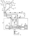
- FIG. 1a shows a schematic of the phaser of the present invention in the null position.
- Hydraulic fluid enters line 118 from a pressurized source to the remotely or separately located control system from the rotor and housing, indicated in the figure by dashed box 130.
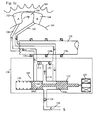
- the control system 130 includes the spool valve 109, the actuator 103, common line 116, check valves 112, 114 and portions of advance line 108 and retard line 110.
- the spool valve 109 is comprised of a spool 104 with multiple lands 104a, 104b slidably received by bore 122. One side of the spool 104 is biased by spring 120 and the other side of the spool 104 is biased by actuator 103.
- Advance and retard lines 108 and 110 lead from the remotely mounted control system 130, through the camshaft 126 to the advance chamber 102 and the retard chamber 104 located in the housing 105.
- Seals 128a, 128b, and 128c are located around the camshaft 126 at the interface between the variable cam timing (VCT) system and the remote control system 130. Specifically, outboard seals 128a, 128c limit the leakage of fluid within the cam torque actuated (CTA) VCT system to atmosphere and the seal 128c in the center of the advance and retard passages 108, 110 limits leakage of fluid from the advance chamber 102 to the retard chamber 104.
- VCT variable cam timing
- fluid from the supply enters the spool valve 104 and moves through common line 116 and check valves 112, 114 to the advance line 108 and the retard line 110 respectively. From the advance line 108 and the retard line 110 fluid enters the advance chamber 102 and the retard chamber 104.
- the spool 104 When the force of the spring 120 is less than the force of the actuator 103, the spool 104 is moved to the left, as shown in Fig. 1b, to the retard position. In the retard position, fluid exits the advance chamber 102 through advance line 108 and the camshaft 126 to the remote control system 130 and into the spool valve 109. Fluid in the spool valve 109 and from supply line 118 enters common line 116 and moves through check valve 114 to retard line 110 and to the retard chamber 104, forcing the vane 106 to move to the left as shown by the arrow. Spool land 104b blocks fluid from the retard chamber 104 from entering the spool valve 109. Check valve 114 does not allow fluid to exit from the retard chamber 104.
- Figure 2a shows a prior art phaser and its length 32.
- Figure 2b shows the phaser of the present invention and its length 132.
- the phaser in Figure 2b has a considerably shorter length 132 than the prior art, since the control system is located remotely.
- Significant leakage that would render the phaser from performing is prevented by placement of seals 128a, 128b and 128c.
- Seals 128a and 128c limit the leakage of fluid within the cam torque actuated (CTA) VCT system to atmosphere and the seal 128c in the center of the advance and retard passages 108, 110 limits leakage of fluid from the advance chamber to the retard chamber.
- CTA cam torque actuated
- the spool valve is not limited to the arrangement, shape, or number of lands of the spool shown in the figures.
- check valves 112 and 114 may be incorporated into the spool or spool valve as disclosed in Application Serial No. 10/952,054 filed 9/28/2004 and entitled "CONTROL VALVE WITH INTEGRATED CHECK VALVES" and is hereby incorporated by reference.
- the actuator 103 may be hydraulic, electric, a differential pressure control system (DPCS), or a variable force solenoid (VFS).
- check valve 124 may be present in supply line 118 to limit pressure feedback to the oil supply system.
- the check valves may be comprised of a ball and a seat, as shown in the figures, or other types of check valves may used, including band check valves, disc check valves, and cone-type.
- remote as used in this application is to mean separate from the housing and the rotor.
- Figures 3 and 4 show schematics of an alternative embodiment.
- the cylinder head and the camshaft are made of different materials, each with a different coefficient of thermal expansion, so as the temperature in the engine increases, the aluminum cylinder head expands faster than the iron camshaft. Since the cylinder head directly surrounds the camshaft, clearances in the camshaft expand as the cylinder head expands.
- the camshaft and mounting flange which is attached to a phaser, contains passages 208, 210 to the advance and retard chambers (not shown) on either side of the vane, to deliver fluid from the control system 130 of Figures 1a through 1c to the chambers and run through the camshaft 226 and cylinder head 234.
- the camshaft 226 is surrounded by a steel sleeve 236 and the cylinder head 234 as shown in Figures 3 and 4.
Landscapes
- Engineering & Computer Science (AREA)
- Mechanical Engineering (AREA)
- General Engineering & Computer Science (AREA)
- Valve Device For Special Equipments (AREA)
Applications Claiming Priority (1)
| Application Number | Priority Date | Filing Date | Title |
|---|---|---|---|
| US11/017,605 US6971354B1 (en) | 2004-12-20 | 2004-12-20 | Variable camshaft timing system with remotely located control system |
Publications (2)
| Publication Number | Publication Date |
|---|---|
| EP1672185A1 true EP1672185A1 (de) | 2006-06-21 |
| EP1672185B1 EP1672185B1 (de) | 2009-03-25 |
Family
ID=35430275
Family Applications (1)
| Application Number | Title | Priority Date | Filing Date |
|---|---|---|---|
| EP05025536A Expired - Lifetime EP1672185B1 (de) | 2004-12-20 | 2005-11-23 | Nockenwellenzeitsteuerungseinrichtung mit räumlich entfertem Kontrollsystem |
Country Status (4)
| Country | Link |
|---|---|
| US (1) | US6971354B1 (de) |
| EP (1) | EP1672185B1 (de) |
| JP (1) | JP2006177343A (de) |
| DE (1) | DE602005013477D1 (de) |
Families Citing this family (5)
| Publication number | Priority date | Publication date | Assignee | Title |
|---|---|---|---|---|
| US8291876B2 (en) * | 2008-01-29 | 2012-10-23 | Comptetition Cams Inc. | Camshaft variable timing limiting devices, methods of assembly, and uses thereof |
| US9080471B2 (en) | 2010-11-02 | 2015-07-14 | Borgwarner, Inc. | Cam torque actuated phaser with mid position lock |
| KR101534709B1 (ko) * | 2013-12-18 | 2015-07-08 | 현대자동차 주식회사 | 가변 압축비 엔진 |
| DE102015208693A1 (de) * | 2015-05-11 | 2016-11-17 | Thyssenkrupp Ag | Nockenwellensegment mit Nockenwellenlager |
| US11174761B1 (en) | 2020-05-15 | 2021-11-16 | Borgwarner, Inc. | Variable camshaft timing (VCT) phaser assembly and control valve installed remotely |
Citations (3)
| Publication number | Priority date | Publication date | Assignee | Title |
|---|---|---|---|---|
| US5176455A (en) * | 1991-07-18 | 1993-01-05 | Rockwell International Corporation | Gradated hydrostatic bearing |
| EP1113153A2 (de) * | 1999-12-28 | 2001-07-04 | BorgWarner Inc. | Mehrfachverstellbare und mit Motoröldruck angetriebene variable Nockenwellenzeitsteuerungseinrichtung |
| EP1128026A2 (de) * | 1999-12-28 | 2001-08-29 | Borg Warner Inc. | Variable Ventilsteuerungseinrichtung mit einem Verriegelungsschieber |
Family Cites Families (26)
| Publication number | Priority date | Publication date | Assignee | Title |
|---|---|---|---|---|
| US5046460A (en) | 1989-10-16 | 1991-09-10 | Borg-Warner Automotive Transmission & Engine Components Corporation | Variable camshaft timing for internal combustion engine |
| US5107804A (en) | 1989-10-16 | 1992-04-28 | Borg-Warner Automotive Transmission & Engine Components Corporation | Variable camshaft timing for internal combustion engine |
| US5361735A (en) | 1989-10-16 | 1994-11-08 | Borg-Warner Automotive Transmission & Engine Components Corporation | Belt driven variable camshaft timing system |
| US5002023A (en) | 1989-10-16 | 1991-03-26 | Borg-Warner Automotive, Inc. | Variable camshaft timing for internal combustion engine |
| US5172659A (en) | 1989-10-16 | 1992-12-22 | Borg-Warner Automotive Transmission & Engine Components Corporation | Differential pressure control system for variable camshaft timing system |
| US5107805A (en) | 1991-07-18 | 1992-04-28 | Borg-Warner Automotive Transmission & Engine Components Corporation | Camshaft with extra cam to increase the magnitude of torque pulsations therein |
| US5289805A (en) | 1992-03-05 | 1994-03-01 | Borg-Warner Automotive Transmission & Engine Components Corporation | Self-calibrating variable camshaft timing system |
| US5184578A (en) | 1992-03-05 | 1993-02-09 | Borg-Warner Automotive Transmission & Engine Components Corporation | VCT system having robust closed loop control employing dual loop approach having hydraulic pilot stage with a PWM solenoid |
| DE4212550C2 (de) | 1992-04-15 | 1998-12-10 | Hydraulik Ring Gmbh | Ventilanordnung mit einem Wegeventil |
| US5497738A (en) | 1992-09-03 | 1996-03-12 | Borg-Warner Automotive, Inc. | VCT control with a direct electromechanical actuator |
| JP3198772B2 (ja) * | 1993-03-10 | 2001-08-13 | トヨタ自動車株式会社 | 内燃機関の動弁装置におけるカム切替機構 |
| JPH07280788A (ja) | 1994-04-14 | 1995-10-27 | Tosoh Corp | チェックバルブの自己診断機能を有するポンプ |
| JP3384559B2 (ja) * | 1994-08-29 | 2003-03-10 | 株式会社デンソー | 内燃機関用バルブタイミング調整装置 |
| US5657725A (en) | 1994-09-15 | 1997-08-19 | Borg-Warner Automotive, Inc. | VCT system utilizing engine oil pressure for actuation |
| JP3600397B2 (ja) | 1997-03-19 | 2004-12-15 | 株式会社日立ユニシアオートモティブ | 内燃機関のバルブタイミング制御装置 |
| JPH1113430A (ja) | 1997-06-24 | 1999-01-19 | Toyota Motor Corp | 内燃機関のバルブタイミング制御装置 |
| JPH11343820A (ja) | 1998-06-03 | 1999-12-14 | Unisia Jecs Corp | 内燃機関のバルブタイミング制御装置 |
| US6250265B1 (en) | 1999-06-30 | 2001-06-26 | Borgwarner Inc. | Variable valve timing with actuator locking for internal combustion engine |
| US6263846B1 (en) | 1999-12-28 | 2001-07-24 | Borgwarner Inc. | Control valve strategy for vane-type variable camshaft timing system |
| US6311655B1 (en) | 2000-01-21 | 2001-11-06 | Borgwarner Inc. | Multi-position variable cam timing system having a vane-mounted locking-piston device |
| JP4465899B2 (ja) | 2001-02-22 | 2010-05-26 | アイシン精機株式会社 | 弁開閉時期制御装置 |
| US6481402B1 (en) * | 2001-07-11 | 2002-11-19 | Borgwarner Inc. | Variable camshaft timing system with pin-style lock between relatively oscillatable components |
| US6763791B2 (en) | 2001-08-14 | 2004-07-20 | Borgwarner Inc. | Cam phaser for engines having two check valves in rotor between chambers and spool valve |
| DE10143433B4 (de) | 2001-09-05 | 2013-09-26 | Hilite Germany Gmbh | Proportionalventil |
| DE10143862A1 (de) * | 2001-09-07 | 2003-03-27 | Ina Schaeffler Kg | Vorrichtung zum Verändern der Steuerzeiten von Gaswechselventilen einer Brennkraftmaschine, insbesondere Rotationskolben-Verstelleinrichtung zur Drehwinkelverstellung einer Nockenwelle gegenüber einer Kurbelwelle |
| US6691656B1 (en) * | 2002-11-27 | 2004-02-17 | Delphi Technologies, Inc. | Cam phaser hydraulic seal assembly |
-
2004
- 2004-12-20 US US11/017,605 patent/US6971354B1/en not_active Expired - Lifetime
-
2005
- 2005-11-21 JP JP2005335535A patent/JP2006177343A/ja active Pending
- 2005-11-23 EP EP05025536A patent/EP1672185B1/de not_active Expired - Lifetime
- 2005-11-23 DE DE602005013477T patent/DE602005013477D1/de not_active Expired - Lifetime
Patent Citations (3)
| Publication number | Priority date | Publication date | Assignee | Title |
|---|---|---|---|---|
| US5176455A (en) * | 1991-07-18 | 1993-01-05 | Rockwell International Corporation | Gradated hydrostatic bearing |
| EP1113153A2 (de) * | 1999-12-28 | 2001-07-04 | BorgWarner Inc. | Mehrfachverstellbare und mit Motoröldruck angetriebene variable Nockenwellenzeitsteuerungseinrichtung |
| EP1128026A2 (de) * | 1999-12-28 | 2001-08-29 | Borg Warner Inc. | Variable Ventilsteuerungseinrichtung mit einem Verriegelungsschieber |
Also Published As
| Publication number | Publication date |
|---|---|
| JP2006177343A (ja) | 2006-07-06 |
| US6971354B1 (en) | 2005-12-06 |
| DE602005013477D1 (de) | 2009-05-07 |
| EP1672185B1 (de) | 2009-03-25 |
Similar Documents
| Publication | Publication Date | Title |
|---|---|---|
| EP2337932B1 (de) | In eine nockenwelle oder in konzentrische nockenwellen eingebauter versteller | |
| US9695716B2 (en) | Multi-mode variable cam timing phaser | |
| JP4377183B2 (ja) | 可変カムシャフトタイミング機構 | |
| US7444971B2 (en) | Valve timing control apparatus of internal combustion engine | |
| JP4530678B2 (ja) | 可変カムタイミング位相器 | |
| US20100084019A1 (en) | Central spool valve | |
| JPH07139319A (ja) | バルブタイミング調整装置 | |
| US6745735B2 (en) | Air venting mechanism for variable camshaft timing devices | |
| CN102278159A (zh) | 流量控制阀 | |
| US6866013B2 (en) | Hydraulic cushioning of a variable valve timing mechanism | |
| WO2007126438A3 (en) | Cta phaser with proportional oil pressure for actuation at engine condition with low cam torsionals | |
| KR20030096051A (ko) | 베인 스타일 캠 페이저에서의 핀 로크의 견고한 작동을보장하는 방법 | |
| US6748912B2 (en) | Method to vent air from a cam phaser with a center mounted spool valve | |
| EP1672185B1 (de) | Nockenwellenzeitsteuerungseinrichtung mit räumlich entfertem Kontrollsystem | |
| US6779501B2 (en) | Method to reduce rotational oscillation of a vane style phaser with a center mounted spool valve | |
| US8561583B2 (en) | Phaser with oil pressure assist | |
| EP2050934B1 (de) | Öldurchflussregelventil für einen Nockenwellenversteller | |
| US11346259B2 (en) | Control apparatus for camshaft phaser |
Legal Events
| Date | Code | Title | Description |
|---|---|---|---|
| PUAI | Public reference made under article 153(3) epc to a published international application that has entered the european phase |
Free format text: ORIGINAL CODE: 0009012 |
|
| AK | Designated contracting states |
Kind code of ref document: A1 Designated state(s): AT BE BG CH CY CZ DE DK EE ES FI FR GB GR HU IE IS IT LI LT LU LV MC NL PL PT RO SE SI SK TR |
|
| AX | Request for extension of the european patent |
Extension state: AL BA HR MK YU |
|
| 17P | Request for examination filed |
Effective date: 20061031 |
|
| AKX | Designation fees paid |
Designated state(s): DE FR IT |
|
| GRAP | Despatch of communication of intention to grant a patent |
Free format text: ORIGINAL CODE: EPIDOSNIGR1 |
|
| GRAS | Grant fee paid |
Free format text: ORIGINAL CODE: EPIDOSNIGR3 |
|
| GRAA | (expected) grant |
Free format text: ORIGINAL CODE: 0009210 |
|
| AK | Designated contracting states |
Kind code of ref document: B1 Designated state(s): DE FR IT |
|
| REF | Corresponds to: |
Ref document number: 602005013477 Country of ref document: DE Date of ref document: 20090507 Kind code of ref document: P |
|
| PLBE | No opposition filed within time limit |
Free format text: ORIGINAL CODE: 0009261 |
|
| STAA | Information on the status of an ep patent application or granted ep patent |
Free format text: STATUS: NO OPPOSITION FILED WITHIN TIME LIMIT |
|
| 26N | No opposition filed |
Effective date: 20091229 |
|
| PGFP | Annual fee paid to national office [announced via postgrant information from national office to epo] |
Ref country code: FR Payment date: 20091120 Year of fee payment: 5 Ref country code: IT Payment date: 20091124 Year of fee payment: 5 |
|
| REG | Reference to a national code |
Ref country code: FR Ref legal event code: ST Effective date: 20110801 |
|
| PG25 | Lapsed in a contracting state [announced via postgrant information from national office to epo] |
Ref country code: FR Free format text: LAPSE BECAUSE OF NON-PAYMENT OF DUE FEES Effective date: 20101130 |
|
| PG25 | Lapsed in a contracting state [announced via postgrant information from national office to epo] |
Ref country code: IT Free format text: LAPSE BECAUSE OF NON-PAYMENT OF DUE FEES Effective date: 20101123 |
|
| PGFP | Annual fee paid to national office [announced via postgrant information from national office to epo] |
Ref country code: DE Payment date: 20181015 Year of fee payment: 14 |
|
| REG | Reference to a national code |
Ref country code: DE Ref legal event code: R119 Ref document number: 602005013477 Country of ref document: DE |
|
| PG25 | Lapsed in a contracting state [announced via postgrant information from national office to epo] |
Ref country code: DE Free format text: LAPSE BECAUSE OF NON-PAYMENT OF DUE FEES Effective date: 20200603 |