EP1672958A2 - Chauffage tubulaire à couche épaisse - Google Patents
Chauffage tubulaire à couche épaisse Download PDFInfo
- Publication number
- EP1672958A2 EP1672958A2 EP05027516A EP05027516A EP1672958A2 EP 1672958 A2 EP1672958 A2 EP 1672958A2 EP 05027516 A EP05027516 A EP 05027516A EP 05027516 A EP05027516 A EP 05027516A EP 1672958 A2 EP1672958 A2 EP 1672958A2
- Authority
- EP
- European Patent Office
- Prior art keywords
- heating
- layer
- heating device
- dielectric layer
- medium
- Prior art date
- Legal status (The legal status is an assumption and is not a legal conclusion. Google has not performed a legal analysis and makes no representation as to the accuracy of the status listed.)
- Granted
Links
- 238000010438 heat treatment Methods 0.000 title claims abstract description 250
- 239000004020 conductor Substances 0.000 claims abstract description 89
- 238000004519 manufacturing process Methods 0.000 claims abstract description 26
- 239000011148 porous material Substances 0.000 claims abstract description 21
- 239000010410 layer Substances 0.000 claims description 191
- 238000000034 method Methods 0.000 claims description 34
- 238000007789 sealing Methods 0.000 claims description 19
- 229910052751 metal Inorganic materials 0.000 claims description 15
- 239000002184 metal Substances 0.000 claims description 15
- 239000011521 glass Substances 0.000 claims description 11
- 239000007788 liquid Substances 0.000 claims description 11
- 230000008569 process Effects 0.000 claims description 11
- 239000000919 ceramic Substances 0.000 claims description 8
- 238000007751 thermal spraying Methods 0.000 claims description 8
- 229910001092 metal group alloy Inorganic materials 0.000 claims description 7
- GWEVSGVZZGPLCZ-UHFFFAOYSA-N Titan oxide Chemical compound O=[Ti]=O GWEVSGVZZGPLCZ-UHFFFAOYSA-N 0.000 claims description 5
- 239000012790 adhesive layer Substances 0.000 claims description 5
- 229920001296 polysiloxane Polymers 0.000 claims description 5
- 229910001220 stainless steel Inorganic materials 0.000 claims description 4
- VYPSYNLAJGMNEJ-UHFFFAOYSA-N Silicium dioxide Chemical compound O=[Si]=O VYPSYNLAJGMNEJ-UHFFFAOYSA-N 0.000 claims description 3
- 239000002131 composite material Substances 0.000 claims description 3
- 239000002905 metal composite material Substances 0.000 claims description 3
- 239000002114 nanocomposite Substances 0.000 claims description 3
- TWNQGVIAIRXVLR-UHFFFAOYSA-N oxo(oxoalumanyloxy)alumane Chemical compound O=[Al]O[Al]=O TWNQGVIAIRXVLR-UHFFFAOYSA-N 0.000 claims description 3
- RVTZCBVAJQQJTK-UHFFFAOYSA-N oxygen(2-);zirconium(4+) Chemical compound [O-2].[O-2].[Zr+4] RVTZCBVAJQQJTK-UHFFFAOYSA-N 0.000 claims description 3
- 229920003055 poly(ester-imide) Polymers 0.000 claims description 3
- 229920002545 silicone oil Polymers 0.000 claims description 3
- 229910001928 zirconium oxide Inorganic materials 0.000 claims description 3
- 239000004962 Polyamide-imide Substances 0.000 claims description 2
- 239000004642 Polyimide Substances 0.000 claims description 2
- 239000000203 mixture Substances 0.000 claims description 2
- 229920002312 polyamide-imide Polymers 0.000 claims description 2
- 229920001721 polyimide Polymers 0.000 claims description 2
- 229910052814 silicon oxide Inorganic materials 0.000 claims description 2
- 239000010935 stainless steel Substances 0.000 claims description 2
- MCMNRKCIXSYSNV-UHFFFAOYSA-N Zirconium dioxide Chemical compound O=[Zr]=O MCMNRKCIXSYSNV-UHFFFAOYSA-N 0.000 claims 2
- CWYNVVGOOAEACU-UHFFFAOYSA-N Fe2+ Chemical compound [Fe+2] CWYNVVGOOAEACU-UHFFFAOYSA-N 0.000 claims 1
- 229910004298 SiO 2 Inorganic materials 0.000 claims 1
- 229910010413 TiO 2 Inorganic materials 0.000 claims 1
- PNEYBMLMFCGWSK-UHFFFAOYSA-N aluminium oxide Inorganic materials [O-2].[O-2].[O-2].[Al+3].[Al+3] PNEYBMLMFCGWSK-UHFFFAOYSA-N 0.000 claims 1
- QDOXWKRWXJOMAK-UHFFFAOYSA-N dichromium trioxide Chemical compound O=[Cr]O[Cr]=O QDOXWKRWXJOMAK-UHFFFAOYSA-N 0.000 claims 1
- KPUWHANPEXNPJT-UHFFFAOYSA-N disiloxane Chemical class [SiH3]O[SiH3] KPUWHANPEXNPJT-UHFFFAOYSA-N 0.000 claims 1
- 238000000576 coating method Methods 0.000 abstract description 11
- 239000011248 coating agent Substances 0.000 abstract description 9
- 230000000181 anti-adherent effect Effects 0.000 abstract 1
- 239000000463 material Substances 0.000 description 31
- 238000013461 design Methods 0.000 description 12
- 238000012544 monitoring process Methods 0.000 description 11
- 239000000126 substance Substances 0.000 description 11
- 230000008901 benefit Effects 0.000 description 10
- XLYOFNOQVPJJNP-UHFFFAOYSA-N water Substances O XLYOFNOQVPJJNP-UHFFFAOYSA-N 0.000 description 10
- 238000009434 installation Methods 0.000 description 9
- 239000002346 layers by function Substances 0.000 description 9
- 230000007797 corrosion Effects 0.000 description 8
- 238000005260 corrosion Methods 0.000 description 8
- 238000005530 etching Methods 0.000 description 7
- KDLHZDBZIXYQEI-UHFFFAOYSA-N Palladium Chemical compound [Pd] KDLHZDBZIXYQEI-UHFFFAOYSA-N 0.000 description 6
- BQCADISMDOOEFD-UHFFFAOYSA-N Silver Chemical compound [Ag] BQCADISMDOOEFD-UHFFFAOYSA-N 0.000 description 6
- 229910000831 Steel Inorganic materials 0.000 description 6
- 238000011161 development Methods 0.000 description 6
- 239000000499 gel Substances 0.000 description 6
- 238000000227 grinding Methods 0.000 description 6
- 230000010354 integration Effects 0.000 description 6
- 229910052709 silver Inorganic materials 0.000 description 6
- 239000004332 silver Substances 0.000 description 6
- 239000010959 steel Substances 0.000 description 6
- 238000005520 cutting process Methods 0.000 description 5
- 210000003298 dental enamel Anatomy 0.000 description 5
- 238000010292 electrical insulation Methods 0.000 description 5
- 238000005516 engineering process Methods 0.000 description 5
- 239000000945 filler Substances 0.000 description 5
- 238000003801 milling Methods 0.000 description 5
- 230000009467 reduction Effects 0.000 description 5
- 238000005406 washing Methods 0.000 description 5
- 238000003466 welding Methods 0.000 description 5
- 235000008733 Citrus aurantifolia Nutrition 0.000 description 4
- 235000011941 Tilia x europaea Nutrition 0.000 description 4
- 238000010276 construction Methods 0.000 description 4
- 239000004571 lime Substances 0.000 description 4
- 150000002739 metals Chemical class 0.000 description 4
- 238000005507 spraying Methods 0.000 description 4
- 238000012546 transfer Methods 0.000 description 4
- PXHVJJICTQNCMI-UHFFFAOYSA-N Nickel Chemical compound [Ni] PXHVJJICTQNCMI-UHFFFAOYSA-N 0.000 description 3
- 238000005270 abrasive blasting Methods 0.000 description 3
- 238000013459 approach Methods 0.000 description 3
- 239000003599 detergent Substances 0.000 description 3
- 230000000694 effects Effects 0.000 description 3
- 239000007789 gas Substances 0.000 description 3
- 239000004922 lacquer Substances 0.000 description 3
- 238000000608 laser ablation Methods 0.000 description 3
- 239000011159 matrix material Substances 0.000 description 3
- 229910052763 palladium Inorganic materials 0.000 description 3
- 239000002245 particle Substances 0.000 description 3
- 230000035515 penetration Effects 0.000 description 3
- 229920000642 polymer Polymers 0.000 description 3
- 230000002829 reductive effect Effects 0.000 description 3
- 230000001105 regulatory effect Effects 0.000 description 3
- 238000007650 screen-printing Methods 0.000 description 3
- 239000002356 single layer Substances 0.000 description 3
- 238000009966 trimming Methods 0.000 description 3
- 229910000975 Carbon steel Inorganic materials 0.000 description 2
- MHAJPDPJQMAIIY-UHFFFAOYSA-N Hydrogen peroxide Chemical compound OO MHAJPDPJQMAIIY-UHFFFAOYSA-N 0.000 description 2
- 239000004809 Teflon Substances 0.000 description 2
- 229920006362 Teflon® Polymers 0.000 description 2
- 238000005422 blasting Methods 0.000 description 2
- 239000010962 carbon steel Substances 0.000 description 2
- 239000010960 cold rolled steel Substances 0.000 description 2
- 229920001940 conductive polymer Polymers 0.000 description 2
- 238000004132 cross linking Methods 0.000 description 2
- 238000001514 detection method Methods 0.000 description 2
- 238000001035 drying Methods 0.000 description 2
- 238000005485 electric heating Methods 0.000 description 2
- 238000010285 flame spraying Methods 0.000 description 2
- 230000017525 heat dissipation Effects 0.000 description 2
- 238000002955 isolation Methods 0.000 description 2
- 238000010297 mechanical methods and process Methods 0.000 description 2
- 239000011156 metal matrix composite Substances 0.000 description 2
- 229910052759 nickel Inorganic materials 0.000 description 2
- 229920000620 organic polymer Polymers 0.000 description 2
- 238000013021 overheating Methods 0.000 description 2
- 238000007750 plasma spraying Methods 0.000 description 2
- -1 polypropylene Polymers 0.000 description 2
- 230000001681 protective effect Effects 0.000 description 2
- 239000011241 protective layer Substances 0.000 description 2
- 230000035484 reaction time Effects 0.000 description 2
- 238000003980 solgel method Methods 0.000 description 2
- OGIDPMRJRNCKJF-UHFFFAOYSA-N titanium oxide Inorganic materials [Ti]=O OGIDPMRJRNCKJF-UHFFFAOYSA-N 0.000 description 2
- 229910000838 Al alloy Inorganic materials 0.000 description 1
- 102000013142 Amylases Human genes 0.000 description 1
- 108010065511 Amylases Proteins 0.000 description 1
- OKTJSMMVPCPJKN-UHFFFAOYSA-N Carbon Chemical compound [C] OKTJSMMVPCPJKN-UHFFFAOYSA-N 0.000 description 1
- 102000005575 Cellulases Human genes 0.000 description 1
- 108010084185 Cellulases Proteins 0.000 description 1
- ZAMOUSCENKQFHK-UHFFFAOYSA-N Chlorine atom Chemical compound [Cl] ZAMOUSCENKQFHK-UHFFFAOYSA-N 0.000 description 1
- RYGMFSIKBFXOCR-UHFFFAOYSA-N Copper Chemical compound [Cu] RYGMFSIKBFXOCR-UHFFFAOYSA-N 0.000 description 1
- 229910000881 Cu alloy Inorganic materials 0.000 description 1
- 102000004190 Enzymes Human genes 0.000 description 1
- 108090000790 Enzymes Proteins 0.000 description 1
- 239000004593 Epoxy Substances 0.000 description 1
- 102000004882 Lipase Human genes 0.000 description 1
- 108090001060 Lipase Proteins 0.000 description 1
- 239000004367 Lipase Substances 0.000 description 1
- 102000035195 Peptidases Human genes 0.000 description 1
- 108091005804 Peptidases Proteins 0.000 description 1
- 239000004743 Polypropylene Substances 0.000 description 1
- 239000004365 Protease Substances 0.000 description 1
- WGLPBDUCMAPZCE-UHFFFAOYSA-N Trioxochromium Chemical compound O=[Cr](=O)=O WGLPBDUCMAPZCE-UHFFFAOYSA-N 0.000 description 1
- 238000002679 ablation Methods 0.000 description 1
- 230000002159 abnormal effect Effects 0.000 description 1
- 239000002253 acid Substances 0.000 description 1
- 230000002378 acidificating effect Effects 0.000 description 1
- 150000007513 acids Chemical class 0.000 description 1
- 239000013543 active substance Substances 0.000 description 1
- 229910052782 aluminium Inorganic materials 0.000 description 1
- XAGFODPZIPBFFR-UHFFFAOYSA-N aluminium Chemical compound [Al] XAGFODPZIPBFFR-UHFFFAOYSA-N 0.000 description 1
- 235000019418 amylase Nutrition 0.000 description 1
- 229940025131 amylases Drugs 0.000 description 1
- 125000000129 anionic group Chemical group 0.000 description 1
- 239000003945 anionic surfactant Substances 0.000 description 1
- 239000010953 base metal Substances 0.000 description 1
- 230000009286 beneficial effect Effects 0.000 description 1
- 230000033228 biological regulation Effects 0.000 description 1
- 230000015572 biosynthetic process Effects 0.000 description 1
- 238000004061 bleaching Methods 0.000 description 1
- 239000007844 bleaching agent Substances 0.000 description 1
- 230000002308 calcification Effects 0.000 description 1
- 239000001913 cellulose Substances 0.000 description 1
- 229920002678 cellulose Polymers 0.000 description 1
- 239000011195 cermet Substances 0.000 description 1
- 230000008859 change Effects 0.000 description 1
- 238000001311 chemical methods and process Methods 0.000 description 1
- 239000000460 chlorine Substances 0.000 description 1
- 229910052801 chlorine Inorganic materials 0.000 description 1
- VNNRSPGTAMTISX-UHFFFAOYSA-N chromium nickel Chemical compound [Cr].[Ni] VNNRSPGTAMTISX-UHFFFAOYSA-N 0.000 description 1
- 229910000423 chromium oxide Inorganic materials 0.000 description 1
- 238000004140 cleaning Methods 0.000 description 1
- 238000010288 cold spraying Methods 0.000 description 1
- 230000002860 competitive effect Effects 0.000 description 1
- 238000011109 contamination Methods 0.000 description 1
- 238000010411 cooking Methods 0.000 description 1
- 238000001816 cooling Methods 0.000 description 1
- 239000010949 copper Substances 0.000 description 1
- 229910052802 copper Inorganic materials 0.000 description 1
- 238000005336 cracking Methods 0.000 description 1
- 238000009792 diffusion process Methods 0.000 description 1
- 229910001039 duplex stainless steel Inorganic materials 0.000 description 1
- 230000008030 elimination Effects 0.000 description 1
- 238000003379 elimination reaction Methods 0.000 description 1
- 238000005265 energy consumption Methods 0.000 description 1
- 229940088598 enzyme Drugs 0.000 description 1
- 150000002118 epoxides Chemical class 0.000 description 1
- 230000003628 erosive effect Effects 0.000 description 1
- 238000001704 evaporation Methods 0.000 description 1
- 230000008020 evaporation Effects 0.000 description 1
- 230000002349 favourable effect Effects 0.000 description 1
- 239000000835 fiber Substances 0.000 description 1
- 239000006260 foam Substances 0.000 description 1
- 238000005242 forging Methods 0.000 description 1
- 229910002804 graphite Inorganic materials 0.000 description 1
- 239000010439 graphite Substances 0.000 description 1
- 230000002209 hydrophobic effect Effects 0.000 description 1
- 230000008595 infiltration Effects 0.000 description 1
- 238000001764 infiltration Methods 0.000 description 1
- 239000010954 inorganic particle Substances 0.000 description 1
- 229920000592 inorganic polymer Polymers 0.000 description 1
- 239000011810 insulating material Substances 0.000 description 1
- 238000009413 insulation Methods 0.000 description 1
- 229910000953 kanthal Inorganic materials 0.000 description 1
- 238000010412 laundry washing Methods 0.000 description 1
- 235000019421 lipase Nutrition 0.000 description 1
- 239000000395 magnesium oxide Substances 0.000 description 1
- CPLXHLVBOLITMK-UHFFFAOYSA-N magnesium oxide Inorganic materials [Mg]=O CPLXHLVBOLITMK-UHFFFAOYSA-N 0.000 description 1
- AXZKOIWUVFPNLO-UHFFFAOYSA-N magnesium;oxygen(2-) Chemical compound [O-2].[Mg+2] AXZKOIWUVFPNLO-UHFFFAOYSA-N 0.000 description 1
- 230000000873 masking effect Effects 0.000 description 1
- 238000005259 measurement Methods 0.000 description 1
- 230000005226 mechanical processes and functions Effects 0.000 description 1
- 238000002844 melting Methods 0.000 description 1
- 230000008018 melting Effects 0.000 description 1
- 239000002086 nanomaterial Substances 0.000 description 1
- 239000002736 nonionic surfactant Substances 0.000 description 1
- 238000010943 off-gassing Methods 0.000 description 1
- 239000007800 oxidant agent Substances 0.000 description 1
- 230000001590 oxidative effect Effects 0.000 description 1
- 239000003973 paint Substances 0.000 description 1
- 238000000059 patterning Methods 0.000 description 1
- 229920001155 polypropylene Polymers 0.000 description 1
- 239000000843 powder Substances 0.000 description 1
- 230000002265 prevention Effects 0.000 description 1
- 230000002940 repellent Effects 0.000 description 1
- 239000005871 repellent Substances 0.000 description 1
- 238000007788 roughening Methods 0.000 description 1
- 238000005488 sandblasting Methods 0.000 description 1
- 239000000565 sealant Substances 0.000 description 1
- 230000035945 sensitivity Effects 0.000 description 1
- 238000007493 shaping process Methods 0.000 description 1
- 239000000344 soap Substances 0.000 description 1
- 239000002689 soil Substances 0.000 description 1
- 238000005476 soldering Methods 0.000 description 1
- 239000002904 solvent Substances 0.000 description 1
- 239000007858 starting material Substances 0.000 description 1
- 239000000758 substrate Substances 0.000 description 1
- 229920001169 thermoplastic Polymers 0.000 description 1
- 229920001187 thermosetting polymer Polymers 0.000 description 1
- 239000004416 thermosoftening plastic Substances 0.000 description 1
- 230000007704 transition Effects 0.000 description 1
- 239000013585 weight reducing agent Substances 0.000 description 1
- 238000004804 winding Methods 0.000 description 1
- 239000010457 zeolite Substances 0.000 description 1
Images



Classifications
-
- H—ELECTRICITY
- H05—ELECTRIC TECHNIQUES NOT OTHERWISE PROVIDED FOR
- H05B—ELECTRIC HEATING; ELECTRIC LIGHT SOURCES NOT OTHERWISE PROVIDED FOR; CIRCUIT ARRANGEMENTS FOR ELECTRIC LIGHT SOURCES, IN GENERAL
- H05B3/00—Ohmic-resistance heating
- H05B3/78—Heating arrangements specially adapted for immersion heating
- H05B3/82—Fixedly-mounted immersion heaters
-
- H—ELECTRICITY
- H05—ELECTRIC TECHNIQUES NOT OTHERWISE PROVIDED FOR
- H05B—ELECTRIC HEATING; ELECTRIC LIGHT SOURCES NOT OTHERWISE PROVIDED FOR; CIRCUIT ARRANGEMENTS FOR ELECTRIC LIGHT SOURCES, IN GENERAL
- H05B3/00—Ohmic-resistance heating
- H05B3/40—Heating elements having the shape of rods or tubes
- H05B3/42—Heating elements having the shape of rods or tubes non-flexible
- H05B3/46—Heating elements having the shape of rods or tubes non-flexible heating conductor mounted on insulating base
-
- H—ELECTRICITY
- H05—ELECTRIC TECHNIQUES NOT OTHERWISE PROVIDED FOR
- H05B—ELECTRIC HEATING; ELECTRIC LIGHT SOURCES NOT OTHERWISE PROVIDED FOR; CIRCUIT ARRANGEMENTS FOR ELECTRIC LIGHT SOURCES, IN GENERAL
- H05B2203/00—Aspects relating to Ohmic resistive heating covered by group H05B3/00
- H05B2203/013—Heaters using resistive films or coatings
-
- H—ELECTRICITY
- H05—ELECTRIC TECHNIQUES NOT OTHERWISE PROVIDED FOR
- H05B—ELECTRIC HEATING; ELECTRIC LIGHT SOURCES NOT OTHERWISE PROVIDED FOR; CIRCUIT ARRANGEMENTS FOR ELECTRIC LIGHT SOURCES, IN GENERAL
- H05B2203/00—Aspects relating to Ohmic resistive heating covered by group H05B3/00
- H05B2203/017—Manufacturing methods or apparatus for heaters
Definitions
- the present invention relates to the field of electrical heating devices, namely heating devices for heating liquid or gaseous media, in particular a thick-film pipe heater gem.
- Another aspect is the modern detergents which contain not only "wash-active substances" such as soap, anionic and non-ionic surfactants.
- the major contributors include water softening aids such as zeolites, foam regulators, bleaches, and fillers. Enzymes are present in almost all detergents, so proteases, lipases and amylases promote soil removal, cellulases cleave cellulose chains and serve to remove split fibers from tissue to be cleaned. Therefore, the outer surface of the heating elements in contact with the medium to be heated are exposed to thermal and strong chemical stresses in addition to the thermal. Thus, this outer surface should have corresponding material properties.
- the chemical resistance with respect to the pH value of the washing solutions used should range from a pH of 5 to 10, since the detergent used, in particular by the use of acids in rinse aids, the pH value in the acidic Move the area.
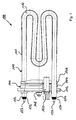
- the tubular heating element 110 consists in principle of a corrosion-resistant tube 111 with two ends 112, 114, in which in the interior 116 in an insulating material z.
- B. magnesium oxide - as a filler and for electrical insulation - embedded high-resistance heating wire, ie the heating element are included.
- the tube 111 serves essentially to protect this electrically insulating filler and the heating conductor relative to the heated and for heat to the medium to be heated.
- the heating conductor can be contacted from the outside via electrical connections 122, 124 at the respective pipe ends 112, 124, wherein the electrical connections 122, 124 are insulated from the pipe 111 by means of seals 132, 134 and the pipe is sealed to the outside.
- tubular heating elements of the prior art A disadvantage of tubular heating elements of the prior art is that very many production steps are required during their production. Also, the arrangement of the heating conductor, the filler with which the heating element is isolated from the (protective) tube and secured, thermally not optimal, since relatively large thermal masses are to be heated; This is especially evident in the thermal reaction time of such tubular heating elements. Also, it is not possible in the pipe heating elements described above to integrate a temperature sensor for detecting the temperature of the medium to be heated in the pipe heater. Finally, due to the construction of the known heating module, much volume of the medium to be heated is displaced.
- the invention has for its object to provide a heater that allows a fast heat transfer to the medium to be heated with a high efficiency, the heater with the same heating capacity as less volume of the medium to be heated to displace as a conventional pipe heater.
- the electric heating device for heating a liquid medium has a main body or base carrier, also called a substrate.
- a main body or base carrier also called a substrate.
- a basic body are in principle all conceivable geometric shapes, depending on application requirements conceivable.
- At least on one surface of the base body at least one heating conductor in the form of a structured resistance heating conductor layer is arranged in a heating region of the heater, which serves to convert electrical energy into heat and has at least two electrical connections which are made and contactable in a connection region of the heating device.
- a dielectric layer is arranged between the base body and the Schuleiter Anlagen a dielectric layer is arranged.
- At least one cover layer electrically insulates the heater trace from the medium, wherein the heater is coated at least in the heating region such that pores in the heat conductor layer and in the dielectric layer are openly sealed to the media, i. penetration or diffusion of the liquid medium into the dielectric layer or heat conductor layer is prevented. Further, the surface of the heater has at least in the heating area against the medium non-stick or anti-soiling properties.
- the base body is a tube closed at least in the area of a first pipe end, that is to say a tubular base body.
- this tubular base body has a heating area which can be brought into contact with the medium to be heated and which is provided with a multiplicity of flow openings in a further development.
- the functional layers namely the dielectric layer, the at least one Schuleiterbahn in the form of the patterned resistance Bankleiter Mrs and the cover layer are provided.
- the embodiment of the heating device according to the invention with an open tube end on the part of the body with the heating area offers, for example, the possibility to connect a pump with which the circulation of the medium to be heated along the inner surface can be additionally increased by supply or by suction. This is not possible with the tubular heaters described above. In this context, it should be noted that it is also possible to close the tubular body at both ends of the pipe.
- flow openings in the base body can have all possible shapes, but they are preferably designed as round holes or elongated holes.
- the flow openings are particularly preferably distributed at regular intervals over the entire heating area. Due to these flow openings, the heater is then in the heating area when used according to the invention - except for the connection area - completely with the entire surface, d. H. the inner surface and the outer surface of the tubular body, with the liquid medium to be heated in direct contact, i. the heating area is submerged or immersed in the medium; this is the case in the connection area only for the inner surface.
- a faster heat transfer to the medium is achieved, and the efficiency of the heater over the conventional tubular heaters is further improved.
- material stresses due to the thermal expansion of the individual materials are significantly reduced or avoided by the good heat dissipation over the entire heating area in the heating device.
- the production is simplified considerably. Further advantages include the material savings by, for example, the elimination of the filler and the associated weight reduction, but also the significantly faster thermal reaction time due to the significantly reduced thermal masses. In addition, a "dry" connection area can be ensured without much effort during operation.
- heat conductor layer With regard to the heat conductor layer, it should be noted that good results have been achieved with metal, metal alloy, eg Kanthal or Nikrothal, but also with ceramic-metal composites, so-called composites. Particularly suitable for this purpose are thermally sprayed or cold-gas-sprayed metals or metal alloys.
- a sol is a colloidal solution with very small, finely divided, freely mobile particles, e.g. Graphite, nickel, silver.
- the sol gels to sol-gel the particles approach each other and form a three-dimensional network. Further heating enhances cross-linking. After cooling, the network is permanent.
- resistance heating elements can be provided both on the inside and on the outside of the main body of the heating device according to the invention.
- Another advantage of the construction of the heating device according to the invention is that very simply one or more electrical sensor elements of various functions can be provided in addition.
- a sensor element can be arranged in isolation on a surface of the base body, wherein its electrical connections are preferably also arranged in the connection area and can be contacted.
- the sensor element can be a very wide variety of sensor types which can be used to monitor the heating device or the heating process or the medium to be heated.
- a temperature sensor can serve for the control and / or thermal monitoring and protection of the resistance heating element. Basically, however, it is also possible to perform the function of monitoring the medium to be heated and the thermal monitoring and protection of the resistance heating element by two or more different sensor elements. It should be noted in particular that the position of a corresponding temperature sensor is crucial, in particular for the precise and reliable control or regulation of a heating element.
- a sensor element may be a temperature sensor which is located directly next to or on the at least one heating conductor track and from this and optionally is arranged electrically isolated and sealed against the medium.
- the heating device according to the invention it is possible in the heating device according to the invention, almost ideal to realize a thermal monitoring of the heating element and / or detection of the medium temperature.
- the corresponding temperature sensor can be arranged almost directly at the respectively relevant measuring location, ie directly on or next to the heating conductor or in direct or indirect thermal contact with the medium. This can advantageously be almost excluded thermal overloading of the heating element.
- the provision of the temperature sensor required for this purpose is much easier to implement than would be possible with a conventional tubular heater.
- the temperature sensor is arranged on the base body in the heating region, it being possible for the temperature sensor to be arranged either on the inner surface or on the outer surface in the case of the tube version. This is particularly contrary to the desire to be able to capture the temperature of the medium to be heated as directly as possible. In the above-described conventional tubular heater this is not possible.
- one or another sensor element can be a securing element for securing the heating device.
- a fuse element for example, interrupt the heating element in a fault or fault, such as a dry run of the heater, interrupt.
- the hedge may consist in a thermal protection but also in an electrical fuse of the heating element.
- the temperature of the heating element is monitored by means of a corresponding temperature sensor and the heating current is interrupted or regulated accordingly.
- the heating current is monitored and interrupted, limited or regulated when a certain value is exceeded.
- the structure of the heater the use of sensor elements in the form of an SMD component (SMD, surface mounted device) allows.
- SMD surface mounted device
- These can be arranged almost at any desired location on the heating device, ie both in the heating area, which is in “wet” area with the medium to be heated in contact and in the connection area, as a “dry” area in the built-in heater in a tub outside, that is shielded from the medium to be heated.
- a tubular base body also allows a reliable detection of the medium temperature even directly in the connection region arranged there, since the inner surface of the base body is in contact here with the medium.
- a sensor element arranged there does not have to be sealed off or insulated from the medium.
- the heating device with a temperature sensor for monitoring or recording the medium temperature in the way to arrange a commercial NTC or PTC element with a sleeve, such as a metal sleeve made of chrome-nickel steel, in the closed end of the tubular body ,
- a sleeve such as a metal sleeve made of chrome-nickel steel
- this pipe end can be particularly easily closed by the sleeve of the temperature sensor is used as a lid, which, for example, when the tubular body and the sleeve are made of metal, can be materially connected by welding with the base body made of metal.
- the temperature sensor is particularly advantageous with the medium to be heated in direct contact.
- sensors for other physical measured variables can also be used as sensor elements at the above positions, such as, for example, a pressure sensor or a sensor for detecting the pH, etc.
- any material with good thermal conductivity and at the same time sufficiently high melting point or a small coefficient of thermal expansion is suitable for the main body.
- An austenitic or a ferritic or duplex stainless steel is preferred for the main body, but also Non-ferrous metals such as aluminum, aluminum alloys, copper, copper alloys are suitable.
- carbon steel for example cold rolled steel.
- the base body can also be made of a ceramic, glass or a metal-ceramic composite, such as a metal matrix composite or cermet.
- a dielectric layer as a first covering layer with a thermal spraying method is for electrical insulation directly on the base body.
- Ceramic layers preferably of aluminum oxide, zirconium oxide, titanium oxide, chromium oxide, glass frit such as borosilicate or a mixture thereof, have proven to be suitable for this purpose.
- an enamel layer or glass layer is suitable as the first cover layer.
- the dielectric layer can also be applied by means of the abovementioned sol-gel method, silicon oxide, titanium oxide, zirconium oxide and aluminum oxide sol gels having proven particularly suitable.
- the dielectric layer and the resistance-Heizleiter für when generated by a thermal spraying method such as atmospheric plasma spraying (APS), high velocity flame spraying (HVOF), powder flame spraying, arc and cold gas spraying or by means of a sol-gel process particularly good mechanical properties exhibit.
- APS atmospheric plasma spraying
- HVOF high velocity flame spraying
- powder flame spraying powder flame spraying
- arc and cold gas spraying or by means of a sol-gel process particularly good mechanical properties exhibit.
- the heater is therefore at least in the heating area, d. H. in the wet area, provided with an applied medium-tight and electrically insulating cover layer.
- This layer should have a thermal conductivity in the range of 1 to 50 W / mK.
- this covering layer can of course also be composed of several layers, one of which is required in each case Functions “electrically isolating", “against the medium to be heated caulking or sealing” and has an “anti-Soiling property”.
- nanocomposite coatings such as organic paints or coatings with inorganic-organic polymer matrix with incorporated inorganic particles, siloxanes and silicone oils. These materials penetrate into the pores of the porous layers and seal them against the penetration of the liquid to be heated medium, such as water.
- the outer surface is equipped with the non-stick or anti-soiling properties.
- the topcoat is designed so that neither lime nor other organic substances can deposit on the heater in the heating area. This ensures a constant and uniform heat transfer from the heating to the medium via the heating area.
- the sealing or pore-sealing cover layer itself already has anti-soiling properties.
- the covering layer can be, for example, a nanostructured protective layer, for which nanostructured materials or material combinations are preferably used.
- a single layer embodiment of the cover layer i.
- Pore sealing, electrical insulation and anti-soiling property for example, a hybrid polymer, which is applied as a sol-gel coating, for example, with a hybrid polymer with an inorganic-organic polymer matrix, is suitable. Namely, the hybrid polymer is thin enough to penetrate into the open pores of the porous layers and additionally forms a dense film on the surface by crosslinking.
- the hydrophobic sol-gel surfaces are not only dirt repellent, they also increase the corrosion resistance of the coated resistive heat conductor layer.
- topcoat In the case of a cover layer in multilayer design, silicones or modified silicones, polyimides, polyamideimide, polyesterimides or modified polyesterimides have proven suitable for the topcoat. But also glass or ceramic layers by means of screen printing or spraying followed by Drying and baking are applied. An important feature of the topcoat here is still to prevent outgassing of the covering layer which seals the pores in the dielectric layer and the resistance heating conductor layer.
- both the dielectric layer and the cover layer of enamel or glass since both requirements are met by these substances in terms of the necessary electrical insulation and the seal against the medium to be heated.
- the base body can be made from inexpensive cold rolled steel as the starting material.
- Hotspots to be considered in this context during operation sites are considered in a heater where sometimes significant excess temperatures occur. Such hotspots can occur due to local external contamination, but also due to the design caused at certain points of the heating element. For example, in the connection region of the heating device, it is not desirable for the heating conductor to convert electrical energy into heat there. But even at so-called reversal points of the heating element, which are necessary at least once at the open end of the pipe, the occurrence of such local overheating was found.
- the Schuleiterbahn are set at reversal points and in the connection area with respect to the remaining Schuleiterbahn that they have a lower resistivity at such locations.
- This can be achieved in principle by increasing the effective heating conductor cross section at reversal points or in the connection region, for example by providing more heating conductor material.
- the Schuleiterbahn at the reversal points or in the connection area of a resistive material having a higher conductivity than the remaining Schuleiterbahn or provided there on the Schuleiterbahn an additional Schuleitermaterial with a lower electrical resistance or is applied.
- the invention preferably uses thermally sprayed or cold-gas sprayed metals or metal alloys, but also thick-film pastes, such as silver / palladium pastes, or electrically conductive polymers, such as silver-filled epoxide.
- connection region it should be noted that if the connections and optionally the part of the heating conductors have a lower electrical resistance from the connection region to the heating region of the at least one heating element than the remaining part of the resistance heating element, the connection region of the heating device according to the invention thereby forms a "cold zone". represents, d. H. a zone in which almost no heat is dissipated by the heating element. This additionally ensures that when the medium temperature in the connection area is detected, it can be measured correctly and is not falsified by heat from the heating conductor.
- a high-voltage resistance of at least 1250VAC, preferably 3750VAC, a maximum leakage current of 0.75mA, preferably 0 , 25mA, a chemical stability to the medium in a PH range of 5 to 10, preferably 7 to 10 and a thermal conductivity of at least 1 W / mK, preferably from 10 to 50W / mK can be achieved.
- a development of the heating device according to the invention consists in the integration of a heating device according to the invention or several heating devices according to the invention in a heating module, wherein substantially between the connection area and the heating area on the one or more heating devices arranged in parallel to a running around the body seal to seal a mounting hole For the heating module is arranged.
- a seal can be embodied, for example, as a conical seal, which is injection-molded directly onto the heating device, for example with a material suitable for a seal, with simultaneous corresponding shaping. This ensures a seal between the heating area and the connection area at the same time.
- a refinement of the heating module consisting of providing a flange assembly with standard dimensions instead of the above-mentioned seal.
- a flange assembly then essentially comprises at least one flange, a clamping piece and a seal arranged between flange and clamping piece, wherein the at least one heating devices are fixed to the flange or the clamping piece and the seal is arranged between the connection region and the heating region.
- connection plug part which for example offers a standardized plug connection, can be provided.
- the method for producing a heating device of the invention basically consists of the following steps: producing a basic body; Applying a first electrically insulating dielectric layer to the base body using one of the above-mentioned thermal spraying methods; Applying at least one structured heating conductor layer to the dielectric layer by one of the above-mentioned thermal spraying methods; and applying an electrically insulating, medium-tight and non-stick properties covering layer on the heater at least in the heating region, wherein pores in the dielectric layer and the Kleinleitertik are sealed medium-tight.
- the step of applying an electrically insulating, medium-tight and non-stick properties having cover layer can be performed in addition to a single-layer embodiment of the following intermediate steps as a two-layer design with the following steps: applying at least in the heating of a first the pores in the dielectric layer and the heat conductor layer medium-tight sealing sealant layer; and applying at least in the heating region a second nanostructured anti-soiling layer over the cover layer.
- the nanostructured anti-soiling layer has to electrically isolate the properties from the medium.
- a step may additionally be provided for producing expansion joints in the dielectric layer next to and / or between heating conductor tracks in the structured heating conductor layer.
- the dielectric layer is applied by means of one of the abovementioned methods, preferably by means of thermal spraying or cold gas spraying.
- the heating conductor layer is applied by means of one of the abovementioned methods, preferably by means of a thermal or a cold spraying method. It is possible by laser structuring, water jet cutting, laser micro jet method, sandblasting, etching, milling or grinding of the entire surface applied Edelleiter für to give the desired Schuleiter Modell, whereby different temperature ranges can be created, but also the electrical heating of the heater can be set at a given supply voltage can.
- heating conductor structure by a stencil technique.
- a template made of a non-stick material on the dielectric layer is applied (laminated or screen printed) and then applied the Schuleitertik. After applying the heat conductor layer, the template is then removed again.
- heating conductor structures have become also successfully produced by direct structured coating with a fine coating jet.
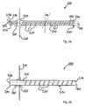
- FIG. 2 a shows a plan view of an exemplary embodiment of a thick-film heater according to the invention, which is embodied as a thick-film pipe heater 200.
- a tubular body 201 with an open tube end 202 and a closed tube end 204 which is closed by a cover 206.
- the thick-film tube heater 200 is shown schematically in its installed position in a tub wall 210.
- a seal 220 in the form of a conical seal is sprayed onto the thick-layer tube heater 200.
- the connection area thus lies on the dry side of the tub and extends from the closed tube end 204 to the tub wall 210 defined plane.
- the heating area of the thick film tube heater 200 is on the right side of the tub wall 210 in the so-called wet area, i. H. is in direct contact with the medium to be heated during operation.
- the heating area extends approximately from the tub wall 210 to the open tube end 202.
- flow openings 230 which are arranged regularly spaced from each other over the entire heating area.
- the flow openings 230 here have the shape of oblong holes, which are formed obliquely to a vertical pipe cross-section with an angle ⁇ in the base body 201 of the thick-film pipe heater 200.
- the heating element 240 is applied to the base body 201, which extends bifilar guided over the entire heating area.
- connection area electrical connections 252 and 254 for the heating conductor 240 are arranged.
- the electrical connections 252, 254 are made by using a material with a lower electrical resistance or by applying additional interconnect material compared to the remaining heating conductor 240 as so-called cold connections.
- a temperature sensor 260 for detecting the temperature of the medium to be heated is provided in the connection region. It should be noted that the electrical connections of the temperature sensor 260 can not be seen in FIG. 2 a, but they are fundamentally similar to the electrical connections or conductor tracks of the heating conductor 240.
- FIG. 2b shows a sectional view of the thick film tube heater 200 of FIG. 2a.
- Fig. 2b is one of the basic advantages of the thick-film tube heater 200 according to the invention, which is that in the heating both the outer surface 212 and the inner surface 214 of the tubular body 201 is in contact with the medium to be heated. Thereby, together with the regularly spaced flow openings 230, an optimal circulation of the medium to be heated on or along the surface of the thick-film pipe heater 200 and thus a faster removal of heat is ensured.
- the medium to be heated is also in the connection area on the inner surface 214 with the main body 201 of the thick-film tube heater 200 in contact and thus detected in the connection area by means of the temperature sensor 260 very accurately and unadulterated by the heating effect of the heating can be.
- FIG. 2b Also clearly visible in FIG. 2b is the embodiment of the conical seal 220 which, for example, can be molded on the outside by means of a spraying process at the end of production of the thick-film tube heater 200 according to the invention between the connection region and the heating region.
- This embodiment ensures a simple sealing of the connection area with the medium at the transition between the outer surface 212 and the seal 220, and secondly, the thick-layer tube heater 200, together with the seal 220, forms a heating module which is at the place of intended use Use very easy to install.
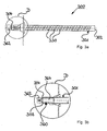
- Fig. 3a shows a side view of a second embodiment of the invention.
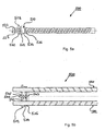
- the major difference between the thick film tube heater 300 shown in FIG. 3a and the thick film tube heater 200 shown in FIGS. 2a and 2b is the integration of a temperature sensor 360 (FIG. 3b) at the closed tube end 304 of the tubular one Grundgropers 301.
- the sealed tube end 304 is closed by integration of the temperature sensor 360 in this tube end 304 in the embodiment of the thick-film tube heater 300 in FIG.
- a commercially available NTC / PTC element in a metal sleeve for.
- a chromium-nickel steel sleeve are used, wherein the steel sleeve also acts as a housing for the sensor as well as a lid for the tubular body 301 at the closed end of the pipe 304.
- FIG. 3b the section of FIG. 3a marked with the dashed circle D is shown as a detail section.
- the integration of the temperature sensor 360 can be seen with a sleeve in the tubular body 301.
- the sleeve of the temperature sensor 360 can, for example, be connected in a form-fitting manner to the tubular base body 301 by welding at the pipe edge 308.
- the thick-film tube heater 300 thus a very accurate temperature monitoring of the medium to be heated can be guaranteed because, as can be clearly seen in the detail section D of Fig. 3b, the sleeve of the temperature sensor 360 with the medium to be heated facing the outside 364 is almost completely in contact.
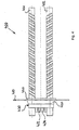
- FIG. 4 shows a top view of a heating module with two thick-film tube heaters 401 and 402 according to the invention, which in terms of their structure substantially correspond to the thick-film tube heater 200 of FIGS. 2a and 2b.
- the heating module 400 shown in FIG. 4 is an example of how several of the thick-film pipe heaters according to the invention can be integrated particularly simply and advantageously arranged parallel to one another in a heating module.
- the individual thick-film pipe heaters 401, 402 can be connected both electrically in parallel and in series, depending on the requirements of the respective field of use.
- the heating module 400 has a seal 420 for installation in a tub wall 410, which in turn is arranged between the connection area and the heating area of the respective thick-film tube heaters 401, 402.
- the seal 420 is essentially again a conical seal, which allows a particularly simple installation in the tub wall 410.
- a so-called RAST housing 430 with two plug connections 432, 434 between the two thick-film tube heaters 401, 402 is provided in this embodiment.
- the thick-film tube heaters according to the invention can of course also be integrated with a corresponding flange assembly into a heating module , wherein the outer dimensions of the flange assembly are then adapted to this quasi-standard of the household appliance industry.
- This has the advantage that manufacturers of the household appliance industry, who want to use these new heating elements, do not adapt the installation openings on their devices or have to change.
- the old technology of tubular heating elements can be replaced without problems and without any time or development effort against the new technology according to the present invention.
- FIG. 5 a shows a side view of the heating module 500 with a flange assembly 510, which consists essentially of a flange 512, a seal 514 and a clamping piece 516.
- a connection area of one of the two thick-film tube heaters (FIGS. 5b: 501, 502) of the heating module 500.
- the connection area there are the two electrical connections 522, 524 and also the corresponding connections for a temperature sensor 530 provided in SMD design.
- a connection lug 518 for connecting a protective conductor to the flange 512 can be seen.
- FIG. 5b shows a plan view of a cross-section of the heating module 500 of FIG. 5a. It can easily be seen that the two thick-film tube heaters 501, 502 are each mechanically fixed in or on the flange 512, wherein the seal 514 is arranged between the flange 512 and the clamping piece 516.
- a through hole is provided which extends through both the clamping piece 516, the seal 514 and the flange 512, through which through-hole a screw 542 is guided, which is pressed with a screw 543 in the clamping piece 516 and thereby against a rotation relative to the clamping piece 516 is secured.
- the screw end 544 opposite the screw end 543 protrudes from the flange and is provided there with a nut 545.
- the seal 514 swells at the periphery and seals against the mounting opening of the container (not shown). from. It should be noted that the flange assembly 510 is also designed this way may be that the clamping piece 516 is fixed to the thick-film tube heaters 501, 502 and the flange 512 remains movable.
- a stainless steel pipe in particular of an austinitic or ferritic stainless steel, is particularly suitable because of its corrosion resistance.
- a stainless steel pipe in particular of an austinitic or ferritic stainless steel, is particularly suitable because of its corrosion resistance.
- Grundköper but basically any metal pipe can be used, in which optionally an additional corrosion protection is applied;
- the tubular base body, or any other geometric base body is made of a cold strip steel section.
- a tubular Grundköper from a flat strip of material, in which the flow openings are punched or are to produce, by winding and then form-fitting connection of the abutting edges.
- This Grundköper is then closed at the pipe end to which the connection area is to be provided with a lid or, if provided in the pipe end, the installation of a temperature sensor with corresponding sleeve-shaped housing, left open. But it can also be attached at this point a corresponding sleeve, preferably made of the same material as the body, instead of the lid.
- an additional preparatory method step may be inserted, which consists of suitably roughening the surface of the tubular base body by a radiating, etching or grinding process.
- the base body Since the preferred material for the base body is a metal which is inherently electrically conductive, the base body must be electrically insulated from the heat conductor to be applied.
- a first electrically insulating dielectric layer is applied to the base body substantially over the entire surface of the base body.
- the dielectric layer is applied by means of one of the aforementioned methods.
- an enamel or glass layer is also suitable.
- expansion joints may be provided in the first cover layer at this point in the production process.
- these expansion joints are arranged such that they are between and / or adjacent to those to be applied later Schuleiterbahnen lie.
- the expansion joints may be produced by means of a water jet cutting process, laser ablation processes or other suitable mechanical processes such as grinding, milling, blasting (in stencil technology or directly applied). But also chemical processes, such as etching, can be used.
- the dielectric layer is a porous layer, in particular a layer with open pores, in order to ensure a sufficient sealing, in particular of the end faces of the dielectric layer in relation to the medium to be heated in later use,
- the area around the edges of the flow openings and at the pipe ends or the edges of the body should not be covered by the dielectric layer. This can be achieved by masking the slots or tube ends before applying the dielectric layer.
- abrasive process abrasive process
- any other suitable mechanical method such as grinding, milling or abrasive blasting using stencil technology or in direct application, can be used.
- Even chemical ablation processes, such as etching are possible.
- the heating conductor layer is applied to the tubular base body.
- metals, metal alloys, ceramic-metal composites (so-called metal matrix composites or cermets) which are applied to the dielectric layer by means of one of the methods mentioned at the outset are suitable for the heating conductor layer.
- Successful trials have also been undertaken by means of screen-printed and subsequently fired resistor pastes.
- the heating element is preferably performed bifilar over the surface of the body and therefore a reversal point must be provided at the open end of the pipe.
- FIG. 6 This aspect is shown in FIG. 6 in a detailed view of a heating conductor inversion point 630 on a thick-film pipe heater 600 according to the invention.
- the detailed drawing shows the open tube end 602 of the tubular base body 601 with the Bankleiterbahnen 610 and a flow opening 620.
- the pores of the porous dielectric layer and the porous resistance Schuleiter Mrs are sealed by means of a single or multi-layer system and electrically isolated from the medium in operation during operation.
- a sealing layer and the topcoat are applied in a two-layer process or a single layer which has all the required properties in a one-layer process.
- a two-layer process is described by way of example: First, a covering layer is applied, for which in principle the materials described below or the respective application methods are suitable.
- inorganic lacquers and lacquers with an organic-inorganic polymer matrix with embedded particles, such as nanocomposite lacquers can be used here. Silicones and silicone oils are also suitable for sealing the pores in the porous layers.
- the heater is still provided with a topcoat, such as a nanostructured anti-soiling layer.
- a topcoat such as a nanostructured anti-soiling layer.
- the particularly advantageous effect of such a layer lies in the reduction of cooking noise or the prevention of limescale, ie lime deposits. Furthermore, these layers are particularly mechanically resistant.
- FIG. 7a to 7d show schematic detail views of a section through the tubular jacket 701 of the tubular main body and the functional layers, wherein in particular the open tube end 702 of the thick-film tube heater as well as the nearest flow opening 730 are shown.
- the layer structure shown in each case in FIGS. 7a and 7b relates to the embodiment of a heating device of the invention, in which a corrosion-resistant material was used for the base body, such as an alloyed steel or a ceramic.
- the basic body does not necessarily have to be completely sealed against the medium.
- the heating element 720 is electrically insulated from the medium to be heated by means of a cover layer 750 and sealed.
- a covering of the end faces 712 of the dielectric layer 710 was additionally provided, because here it consists of a porous layer, ie a layer which is not dense with respect to the medium to be heated, as is the case with thermally sprayed materials. consists.
- a porous layer ie a layer which is not dense with respect to the medium to be heated, as is the case with thermally sprayed materials.
- the layer structure shown in each case in FIGS. 7c and 7d relates to the embodiment of a heating device of the invention, in which a corrosion-prone material was used for the base body, such. As a carbon steel. Therefore, in these embodiments, the main body has been completely sealed off from the medium by the cover layer 750.
- both the dielectric layer 710 and the second cap layer 750 are comprised of an enamel or a glass layer (not shown). It can also be clearly seen in FIGS. 7c and 7d that the covering layer 750 completely seals and electrically insulates the main body 701, the dielectric layer 710 and the resistance heating conductor layer 720 from the outside.
- FIG. 7e shows a further embodiment for the layer construction of the thick-film heater according to the invention.
- an adhesive layer 705 is provided between the surface of the main body 701 and the dielectric layer 710, which ensures improved adhesion of the functional layers on the main body 701.
- the dielectric layer 710 is arranged, on which the heating conductors of the patterned resistance heating conductor layer 720 are located.
- the layers 705, 710 and 720 were applied by a method in which the generated layers have a porous structure; which is desirable as explained above.
- the open pores of these layers are closed by means of a seal 751, ie sealed against the liquid medium to be heated. This seal 751 is indicated in FIG.
- the cross section of the heating conductor inversion point 724 can also be seen as a layered structure (provided with reference numerals in FIGS. 7a and 7d).
- the two heating conductors 721, 722 leading to the heating conductor inversion point 724 can be recognized, which are both connected to one another by interconnect material 727 (approximately the same layer thickness as the resistance heating conductor layer 720) and coated with an additional layer of conductor material 728.
- interconnect material 727 approximately the same layer thickness as the resistance heating conductor layer 720
- additional layer of conductor material 728 for example, a silver / palladium paste can be used in the production.
- Another advantageous aspect of the thick-film heater according to the invention consists in the possibility of the electrical heat output during manufacture individually, d. H. z. B. according to the respective intended application or installation position in the application to be able to adapt.
- two different approaches are available in the thick-film heater of the invention.
- This structuring can be carried out by abrasive techniques, for example by laser structuring, water jet cutting, abrasive blasting, etching, milling and grinding.
- a second possibility to adjust the electric power of the heating conductor is to apply the resistance heating conductor layer with the desired structure directly.
- Template techniques are suitable for this purpose, in which, for example, a mask is applied to the first cover layer by applying an anti-sticking material by means of screen printing, in which case subsequently on the unmasked areas the Schuleitermaterial is applied.
- the application width can be controlled, for example, via the variation of the distance of the jet nozzle from the first covering layer.
- the electric power of the heater can also be adjusted by resistance trimming.
- the electrical resistance and thus implemented in the Schuleiterbahn heat output is made by adjusting the Schuleiterbahnbreite or Schuleiterbahnêtêtêt.
- the resistance trimming over the web width of the heat conductor can be performed as follows: First, the Schuleiterbahn is structured with a sufficient width and thickness on the prepared body, then the electrical resistance of the heating element is measured, from this, the current quotient of the resistivity of the heating element and the cross section and thus the currently required conductor track width are calculated. This calculated width is finally adjusted by appropriate removal of Bankleiterbahnmaterial.
- the resistance trimming on the Schuleiterbahndicke is possible: Here, first, the Schuleiterbahn with a sufficient thickness and width on the structured basic body, then the electrical resistance of the heating element is measured and by so-called “micro forging" the Schuleiterober Designs without abrasive (abrasive) effect with simultaneous measurement of the current resistance, the desired electrical resistance is set.
- the heating power should be able to be regulated in operation as a function of the desired temperature of the medium to be heated.
- a monitoring of the Schuleitertemperatur should be done in order to detect abnormal operation and possibly interrupt the supply of electrical energy to the heating element.
- a temperature sensor in SMD design at any desired location, d. H. in the dry or wet area be provided. At this point it should be pointed out again that this is conceivable both on the outer surface and the inner surface of the tubular body.
- fuse elements can be provided to protect the heat conductor against overheating immediately next to or on an active Schuleiterbahn.
- sensor components in SMD design are fundamentally suitable.
- thick-film fuses can also be integrated at the respective desired location on the surface of the thick-film pipe heater in the above-described production process by means of screen printing or plasma spraying.
- connection plug parts described above can be pushed onto the connection region of the pipe with correspondingly suitable contacting.
- the temperature control or temperature monitoring and the line part can be performed separately or integrated in a male part.
- Suitable methods for connecting the connections to the connection points on the thick-film tube heating are soldering, friction welding, Ultrasonic welding or laser welding. But a contact via suitable spring contacts is possible.
- FIG. 8 a perspective illustration of a heating module 800 with a thick-film tube heater according to the invention in FIG. 8. Shown is a heating module 800 with the tubular base body 801, which is divided functionally into the heating area 810 and the connection area 820. This results in the possibility of a simple installation of the heating module 800 by means of a seal 870 between the heating area 810 and the connection area 820. It has been shown that other standardized installation measures can be provided instead of the (cone) seal.
- the heating conductor 840 extends bifilarly over the tubular base body 801, there is the open tube end 802, in which the flow openings 830 can be seen.
- the tubular design of the heating with the open tube end 802 and the flow openings 830 represents a significant advantage, since this type compared to the conventional tubular heaters, a reduction of the displaced volume of the medium to be heated of about 25% is achieved. In addition, a particularly effective heat transfer to the medium to be heated and thus a faster heating than conventional tubular heaters is achieved.
- the tubular structure of the thick-film tube heater according to the invention is ideal for the direct integration of temperature sensor elements 862, 864 but also other sensors (pressure sensors, pollution sensors, etc.) in SMD design both within, ie in the heating area 810, as well as outside It is also advantageous that in the connection area at the closed pipe end 804 a connection housing 850 with RAST plugs 852, 854 can be provided in a particularly simple manner, which provides a simple and safe Connection of the heating conductor 840 and also the temperature sensor elements 862, 864, for temperature monitoring of the medium to be heated and for thermal protection or monitoring of the heating element Serve 640, allow. Due to the significant reduction of the components of the thick-film pipe heater compared to a conventional pipe heating element - for example shown in FIG.
- the thick-film tube heater according to the invention has a particularly effective protection against calcification and caking of organic substances due to the provided second and third cover layer, resulting in the reliability and Longevity of a thick-film pipe heater according to the invention significantly increased compared to the known tubular heaters.
- the electric heating device has a main body, which may be provided in a heating area with a plurality of flow openings and in a development is a closed at least in the region of a first end tube. At least on one surface of the base body, the functional layers of the heating device are arranged, wherein at least one heating conductor is provided in the form of a structured thermally sprayed resistance Bankleitertik for converting electrical energy into heat with at least two electrical terminals that are designed and contacted in a terminal area, and there is a thermally sprayed dielectric layer between the heat conductor layer and the base body.
- pores of the resistance heating conductor layer and the dielectric layer are sealed against the medium and the resistance heating conductor layer is electrically insulated from the medium, in particular the surface in contact with the liquid medium to be heated during operation has non-stick properties.
Landscapes
- Resistance Heating (AREA)
- Instantaneous Water Boilers, Portable Hot-Water Supply Apparatuses, And Control Of Portable Hot-Water Supply Apparatuses (AREA)
Applications Claiming Priority (1)
| Application Number | Priority Date | Filing Date | Title |
|---|---|---|---|
| DE102004060382A DE102004060382A1 (de) | 2004-12-15 | 2004-12-15 | Dickschicht-Rohr-Heizung |
Publications (3)
| Publication Number | Publication Date |
|---|---|
| EP1672958A2 true EP1672958A2 (fr) | 2006-06-21 |
| EP1672958A3 EP1672958A3 (fr) | 2008-04-23 |
| EP1672958B1 EP1672958B1 (fr) | 2011-11-16 |
Family
ID=35777185
Family Applications (1)
| Application Number | Title | Priority Date | Filing Date |
|---|---|---|---|
| EP05027516A Expired - Lifetime EP1672958B1 (fr) | 2004-12-15 | 2005-12-15 | Chauffage tubulaire à couche épaisse |
Country Status (3)
| Country | Link |
|---|---|
| EP (1) | EP1672958B1 (fr) |
| AT (1) | ATE534266T1 (fr) |
| DE (1) | DE102004060382A1 (fr) |
Cited By (10)
| Publication number | Priority date | Publication date | Assignee | Title |
|---|---|---|---|---|
| WO2008011507A1 (fr) * | 2006-07-20 | 2008-01-24 | Watlow Electric Manufacturing Company | Système chauffant multicouche à revêtements conducteurs |
| DE102008049215A1 (de) | 2008-09-27 | 2010-04-01 | Hotset Heizpatronen U. Zubehör Gmbh | Elektrisches Heizelement für technische Zwecke |
| WO2015025022A1 (fr) * | 2013-08-22 | 2015-02-26 | Continental Automotive Gmbh | Dispositif et procédé de fabrication d'un enroulement chauffant sur un corps de base métallique |
| WO2015026304A1 (fr) * | 2013-08-21 | 2015-02-26 | Ozyegin Universitesi | Nanostructures permanentes induisant le polissage mécano-chimique de nanostructures pour empêcher la formation de tartre sur les éléments chauffants |
| DE102014206592A1 (de) | 2014-04-04 | 2015-10-08 | BSH Hausgeräte GmbH | Heizeinrichtung, Haushaltsgerät und Verfahren |
| ITUA20162359A1 (it) * | 2016-04-06 | 2017-10-06 | De Longhi Appliances Srl | Caldaia |
| WO2020165080A1 (fr) * | 2019-02-12 | 2020-08-20 | Vitesco Technologies GmbH | Dispositif de chauffage comprenant une pluralité d'éléments chauffants électriques |
| CN113905467A (zh) * | 2021-11-04 | 2022-01-07 | 苏州法密利电子科技有限公司 | 一种改进型ptc加热器及其制备方法 |
| DE102021210412A1 (de) | 2021-09-20 | 2023-03-23 | BSH Hausgeräte GmbH | Verfahren zum Herstellen eines Heizelements zur Installation in einer Wasserpumpe |
| US12473694B2 (en) | 2014-12-22 | 2025-11-18 | Celwise Ab | Tool or tool part, system including such a tool or tool part, method of producing such a tool or tool part and method of molding a product from a pulp slurry |
Families Citing this family (2)
| Publication number | Priority date | Publication date | Assignee | Title |
|---|---|---|---|---|
| DE102019103593A1 (de) * | 2019-02-13 | 2020-08-13 | Miele & Cie. Kg | Verfahren und Vorrichtung zum Betrieb eines einen Behandlungsraum aufweisenden Haushaltsgeräts mit einem Heizkörper und Haushaltsgerät |
| DE102022203294A1 (de) | 2022-04-01 | 2023-10-05 | E.G.O. Elektro-Gerätebau GmbH | Verfahren zur Herstellung einer Heizeinrichtung und Heizeinrichtung |
Citations (2)
| Publication number | Priority date | Publication date | Assignee | Title |
|---|---|---|---|---|
| EP0551914B1 (fr) | 1992-01-15 | 1998-11-11 | Elpag Ag Chur | Dispositif pour mettre en place un dispositif de chauffage dans une ouverture d'une paroi d'un réservoir |
| WO2001094861A1 (fr) | 2000-06-08 | 2001-12-13 | Thermowatt S.P.A. | Element chauffant de forme tubulaire |
Family Cites Families (8)
| Publication number | Priority date | Publication date | Assignee | Title |
|---|---|---|---|---|
| US2507750A (en) * | 1948-08-20 | 1950-05-16 | George W Barlow | Hot-water bottle stopper and heat maintainer |
| US2691089A (en) * | 1952-09-04 | 1954-10-05 | Julian A Blais | Hot-water bottle heat stabilizer |
| GB758948A (en) * | 1954-01-29 | 1956-10-10 | Napier & Son Ltd | Electrical surface heating apparatus |
| CH338010A (de) * | 1955-10-26 | 1959-04-30 | Schulthess Willy | Boiler für Warmwasserbereitung |
| FR2074672A1 (fr) * | 1970-01-16 | 1971-10-08 | Ragault Beatrice | |
| DE3512659A1 (de) * | 1985-04-06 | 1986-10-09 | Robert Bosch Gmbh, 7000 Stuttgart | Heizung fuer elektrisch betriebene warmwassergeraete |
| DE19902165A1 (de) * | 1999-01-20 | 2000-08-03 | Egon Kiesling | Beschichtung von elektrischen Heizstäben mit einer Anti-Haft-Versiegelung gegen Zerstörung derselben durch Kalkablagerungen und Kalkfraß |
| DE10062540A1 (de) * | 2000-12-15 | 2002-06-20 | Bleckmann Gmbh Lamprechtshause | Heizvorrichtung mit Aufweitkörper zur Montage in einer Wandöffnung |
-
2004
- 2004-12-15 DE DE102004060382A patent/DE102004060382A1/de not_active Ceased
-
2005
- 2005-12-15 AT AT05027516T patent/ATE534266T1/de active
- 2005-12-15 EP EP05027516A patent/EP1672958B1/fr not_active Expired - Lifetime
Patent Citations (2)
| Publication number | Priority date | Publication date | Assignee | Title |
|---|---|---|---|---|
| EP0551914B1 (fr) | 1992-01-15 | 1998-11-11 | Elpag Ag Chur | Dispositif pour mettre en place un dispositif de chauffage dans une ouverture d'une paroi d'un réservoir |
| WO2001094861A1 (fr) | 2000-06-08 | 2001-12-13 | Thermowatt S.P.A. | Element chauffant de forme tubulaire |
Cited By (16)
| Publication number | Priority date | Publication date | Assignee | Title |
|---|---|---|---|---|
| KR101005733B1 (ko) * | 2006-07-20 | 2011-01-06 | 와틀로 일렉트릭 매뉴팩츄어링 컴파니 | 도전성 오버레이를 가지는 층형 히터 시스템 |
| WO2008011507A1 (fr) * | 2006-07-20 | 2008-01-24 | Watlow Electric Manufacturing Company | Système chauffant multicouche à revêtements conducteurs |
| DE102008049215A1 (de) | 2008-09-27 | 2010-04-01 | Hotset Heizpatronen U. Zubehör Gmbh | Elektrisches Heizelement für technische Zwecke |
| WO2015026304A1 (fr) * | 2013-08-21 | 2015-02-26 | Ozyegin Universitesi | Nanostructures permanentes induisant le polissage mécano-chimique de nanostructures pour empêcher la formation de tartre sur les éléments chauffants |
| US20160201928A1 (en) * | 2013-08-21 | 2016-07-14 | Ozyegin Universitesi | Nanostructure chemical mechanical polishing induced live nano-structures for lime-scale prevention on heating elements |
| WO2015025022A1 (fr) * | 2013-08-22 | 2015-02-26 | Continental Automotive Gmbh | Dispositif et procédé de fabrication d'un enroulement chauffant sur un corps de base métallique |
| DE102014206592A1 (de) | 2014-04-04 | 2015-10-08 | BSH Hausgeräte GmbH | Heizeinrichtung, Haushaltsgerät und Verfahren |
| WO2015150188A1 (fr) * | 2014-04-04 | 2015-10-08 | BSH Hausgeräte GmbH | Dispositif chauffant, appareil ménager et procédé |
| US12473694B2 (en) | 2014-12-22 | 2025-11-18 | Celwise Ab | Tool or tool part, system including such a tool or tool part, method of producing such a tool or tool part and method of molding a product from a pulp slurry |
| ITUA20162359A1 (it) * | 2016-04-06 | 2017-10-06 | De Longhi Appliances Srl | Caldaia |
| CN109312931A (zh) * | 2016-04-06 | 2019-02-05 | 德隆奇电器单股东有限责任公司 | 烧水器 |
| WO2017174712A1 (fr) * | 2016-04-06 | 2017-10-12 | De' Longhi Appliances S.R.L. Con Unico Socio | Chaudière |
| WO2020165080A1 (fr) * | 2019-02-12 | 2020-08-20 | Vitesco Technologies GmbH | Dispositif de chauffage comprenant une pluralité d'éléments chauffants électriques |
| DE102021210412A1 (de) | 2021-09-20 | 2023-03-23 | BSH Hausgeräte GmbH | Verfahren zum Herstellen eines Heizelements zur Installation in einer Wasserpumpe |
| CN113905467A (zh) * | 2021-11-04 | 2022-01-07 | 苏州法密利电子科技有限公司 | 一种改进型ptc加热器及其制备方法 |
| CN113905467B (zh) * | 2021-11-04 | 2023-08-01 | 苏州法密利电子科技有限公司 | 一种改进型ptc加热器及其制备方法 |
Also Published As
| Publication number | Publication date |
|---|---|
| DE102004060382A1 (de) | 2006-06-29 |
| EP1672958A3 (fr) | 2008-04-23 |
| ATE534266T1 (de) | 2011-12-15 |
| EP1672958B1 (fr) | 2011-11-16 |
Similar Documents
| Publication | Publication Date | Title |
|---|---|---|
| EP1672958B1 (fr) | Chauffage tubulaire à couche épaisse | |
| DE60207540T2 (de) | Isolierende schicht für ein heizelement | |
| DE19529627C1 (de) | Thermisch leitende, elektrisch isolierende Verbindung und Verfahren zu seiner Herstellung | |
| DE69834550T2 (de) | Tauchheizkörper | |
| EP3209949B1 (fr) | Chauffage avec capteur de température intégré | |
| WO2013186106A1 (fr) | Dispositif de chauffage électrique pour un véhicule a moteur | |
| EP1692921A1 (fr) | Dispositif de chauffage destine a des fluides, chauffe-eau instantane et leurs procedes de production | |
| EP2215301A1 (fr) | Procédé pour faire fonctionner un lave-linge avec un dispositif de chauffage | |
| DE10021512A1 (de) | Elektrische Heizeinheit, insbesondere für flüssige Medien | |
| WO2013072128A1 (fr) | Capteur d'humidité intégré et procédé de fabrication dudit capteur d'humidité | |
| EP1338174A1 (fr) | Element chauffant electrique | |
| EP2815626A1 (fr) | Procédé de fabrication d'un chauffage de véhicule et chauffage de véhicule | |
| DE2740021A1 (de) | Elektrische bauelemente | |
| EP1293597B1 (fr) | Dispositif de chauffage pour machine à laver | |
| EP2739477A1 (fr) | Poinçon à chaud présentant une microstructure | |
| WO2013120767A1 (fr) | Chauffage de véhicule et procédé de fabrication d'un chauffage de véhicule | |
| EP3417210B1 (fr) | Échangeur de chaleur huile-eau, en particulier pour moteur à combustion interne d'un véhicule automobile | |
| EP3198200B1 (fr) | Plaque de cuisson avec élément de détection et procédé de fabrication d'une plaque de cuisson | |
| DE102014208433A1 (de) | Thermoelektrische Vorrichtung, insbesondere für ein Kraftfahrzeug | |
| WO2017021075A1 (fr) | Dispositif de chauffage pour appareil ménager | |
| WO2022223175A1 (fr) | Dispositif de chauffage d'un milieu | |
| EP1398996B1 (fr) | Elément chauffant plat pour le chauffage direct d'un milieu | |
| EP3329737B1 (fr) | Liaison thermique de structures de couches pulvérisées de dispositifs de chauffage | |
| WO2016082965A1 (fr) | Élément de détection en céramique destiné à un capteur de gaz d'échappement | |
| DE60106440T2 (de) | Verbessertes heizelement |
Legal Events
| Date | Code | Title | Description |
|---|---|---|---|
| PUAI | Public reference made under article 153(3) epc to a published international application that has entered the european phase |
Free format text: ORIGINAL CODE: 0009012 |
|
| AK | Designated contracting states |
Kind code of ref document: A2 Designated state(s): AT BE BG CH CY CZ DE DK EE ES FI FR GB GR HU IE IS IT LI LT LU LV MC NL PL PT RO SE SI SK TR |
|
| AX | Request for extension of the european patent |
Extension state: AL BA HR MK YU |
|
| PUAL | Search report despatched |
Free format text: ORIGINAL CODE: 0009013 |
|
| AK | Designated contracting states |
Kind code of ref document: A3 Designated state(s): AT BE BG CH CY CZ DE DK EE ES FI FR GB GR HU IE IS IT LI LT LU LV MC NL PL PT RO SE SI SK TR |
|
| AX | Request for extension of the european patent |
Extension state: AL BA HR MK YU |
|
| 17P | Request for examination filed |
Effective date: 20081023 |
|
| AKX | Designation fees paid |
Designated state(s): AT BE BG CH CY CZ DE DK EE ES FI FR GB GR HU IE IS IT LI LT LU LV MC NL PL PT RO SE SI SK TR |
|
| 17Q | First examination report despatched |
Effective date: 20090213 |
|
| GRAP | Despatch of communication of intention to grant a patent |
Free format text: ORIGINAL CODE: EPIDOSNIGR1 |
|
| RIN1 | Information on inventor provided before grant (corrected) |
Inventor name: PLESCHINGER, ANDREAS Inventor name: WALLINGER, MARTIN |
|
| GRAS | Grant fee paid |
Free format text: ORIGINAL CODE: EPIDOSNIGR3 |
|
| GRAA | (expected) grant |
Free format text: ORIGINAL CODE: 0009210 |
|
| AK | Designated contracting states |
Kind code of ref document: B1 Designated state(s): AT BE BG CH CY CZ DE DK EE ES FI FR GB GR HU IE IS IT LI LT LU LV MC NL PL PT RO SE SI SK TR |
|
| REG | Reference to a national code |
Ref country code: GB Ref legal event code: FG4D Free format text: NOT ENGLISH |
|
| REG | Reference to a national code |
Ref country code: CH Ref legal event code: EP |
|
| REG | Reference to a national code |
Ref country code: IE Ref legal event code: FG4D Free format text: LANGUAGE OF EP DOCUMENT: GERMAN |
|
| REG | Reference to a national code |
Ref country code: DE Ref legal event code: R096 Ref document number: 502005012134 Country of ref document: DE Effective date: 20120112 |
|
| REG | Reference to a national code |
Ref country code: NL Ref legal event code: VDEP Effective date: 20111116 |
|
| LTIE | Lt: invalidation of european patent or patent extension |
Effective date: 20111116 |
|
| PG25 | Lapsed in a contracting state [announced via postgrant information from national office to epo] |
Ref country code: IS Free format text: LAPSE BECAUSE OF FAILURE TO SUBMIT A TRANSLATION OF THE DESCRIPTION OR TO PAY THE FEE WITHIN THE PRESCRIBED TIME-LIMIT Effective date: 20120316 Ref country code: LT Free format text: LAPSE BECAUSE OF FAILURE TO SUBMIT A TRANSLATION OF THE DESCRIPTION OR TO PAY THE FEE WITHIN THE PRESCRIBED TIME-LIMIT Effective date: 20111116 |
|
| PG25 | Lapsed in a contracting state [announced via postgrant information from national office to epo] |
Ref country code: PL Free format text: LAPSE BECAUSE OF FAILURE TO SUBMIT A TRANSLATION OF THE DESCRIPTION OR TO PAY THE FEE WITHIN THE PRESCRIBED TIME-LIMIT Effective date: 20111116 Ref country code: LV Free format text: LAPSE BECAUSE OF FAILURE TO SUBMIT A TRANSLATION OF THE DESCRIPTION OR TO PAY THE FEE WITHIN THE PRESCRIBED TIME-LIMIT Effective date: 20111116 Ref country code: GR Free format text: LAPSE BECAUSE OF FAILURE TO SUBMIT A TRANSLATION OF THE DESCRIPTION OR TO PAY THE FEE WITHIN THE PRESCRIBED TIME-LIMIT Effective date: 20120217 Ref country code: SI Free format text: LAPSE BECAUSE OF FAILURE TO SUBMIT A TRANSLATION OF THE DESCRIPTION OR TO PAY THE FEE WITHIN THE PRESCRIBED TIME-LIMIT Effective date: 20111116 Ref country code: PT Free format text: LAPSE BECAUSE OF FAILURE TO SUBMIT A TRANSLATION OF THE DESCRIPTION OR TO PAY THE FEE WITHIN THE PRESCRIBED TIME-LIMIT Effective date: 20120316 Ref country code: NL Free format text: LAPSE BECAUSE OF FAILURE TO SUBMIT A TRANSLATION OF THE DESCRIPTION OR TO PAY THE FEE WITHIN THE PRESCRIBED TIME-LIMIT Effective date: 20111116 Ref country code: SE Free format text: LAPSE BECAUSE OF FAILURE TO SUBMIT A TRANSLATION OF THE DESCRIPTION OR TO PAY THE FEE WITHIN THE PRESCRIBED TIME-LIMIT Effective date: 20111116 |
|
| REG | Reference to a national code |
Ref country code: IE Ref legal event code: FD4D |
|
| PG25 | Lapsed in a contracting state [announced via postgrant information from national office to epo] |
Ref country code: CY Free format text: LAPSE BECAUSE OF FAILURE TO SUBMIT A TRANSLATION OF THE DESCRIPTION OR TO PAY THE FEE WITHIN THE PRESCRIBED TIME-LIMIT Effective date: 20111116 |
|
| BERE | Be: lapsed |
Owner name: BLECKMANN GMBH & CO. KG Effective date: 20111231 |
|
| PG25 | Lapsed in a contracting state [announced via postgrant information from national office to epo] |
Ref country code: EE Free format text: LAPSE BECAUSE OF FAILURE TO SUBMIT A TRANSLATION OF THE DESCRIPTION OR TO PAY THE FEE WITHIN THE PRESCRIBED TIME-LIMIT Effective date: 20111116 Ref country code: CZ Free format text: LAPSE BECAUSE OF FAILURE TO SUBMIT A TRANSLATION OF THE DESCRIPTION OR TO PAY THE FEE WITHIN THE PRESCRIBED TIME-LIMIT Effective date: 20111116 Ref country code: BG Free format text: LAPSE BECAUSE OF FAILURE TO SUBMIT A TRANSLATION OF THE DESCRIPTION OR TO PAY THE FEE WITHIN THE PRESCRIBED TIME-LIMIT Effective date: 20120216 Ref country code: MC Free format text: LAPSE BECAUSE OF NON-PAYMENT OF DUE FEES Effective date: 20111231 Ref country code: SK Free format text: LAPSE BECAUSE OF FAILURE TO SUBMIT A TRANSLATION OF THE DESCRIPTION OR TO PAY THE FEE WITHIN THE PRESCRIBED TIME-LIMIT Effective date: 20111116 Ref country code: IE Free format text: LAPSE BECAUSE OF FAILURE TO SUBMIT A TRANSLATION OF THE DESCRIPTION OR TO PAY THE FEE WITHIN THE PRESCRIBED TIME-LIMIT Effective date: 20111116 Ref country code: DK Free format text: LAPSE BECAUSE OF FAILURE TO SUBMIT A TRANSLATION OF THE DESCRIPTION OR TO PAY THE FEE WITHIN THE PRESCRIBED TIME-LIMIT Effective date: 20111116 |
|
| REG | Reference to a national code |
Ref country code: CH Ref legal event code: PL |
|
| PG25 | Lapsed in a contracting state [announced via postgrant information from national office to epo] |
Ref country code: IT Free format text: LAPSE BECAUSE OF FAILURE TO SUBMIT A TRANSLATION OF THE DESCRIPTION OR TO PAY THE FEE WITHIN THE PRESCRIBED TIME-LIMIT Effective date: 20111116 Ref country code: RO Free format text: LAPSE BECAUSE OF FAILURE TO SUBMIT A TRANSLATION OF THE DESCRIPTION OR TO PAY THE FEE WITHIN THE PRESCRIBED TIME-LIMIT Effective date: 20111116 |
|
| PLBE | No opposition filed within time limit |
Free format text: ORIGINAL CODE: 0009261 |
|
| STAA | Information on the status of an ep patent application or granted ep patent |
Free format text: STATUS: NO OPPOSITION FILED WITHIN TIME LIMIT |
|
| 26N | No opposition filed |
Effective date: 20120817 |
|
| PG25 | Lapsed in a contracting state [announced via postgrant information from national office to epo] |
Ref country code: BE Free format text: LAPSE BECAUSE OF NON-PAYMENT OF DUE FEES Effective date: 20111231 Ref country code: CH Free format text: LAPSE BECAUSE OF NON-PAYMENT OF DUE FEES Effective date: 20111231 Ref country code: LI Free format text: LAPSE BECAUSE OF NON-PAYMENT OF DUE FEES Effective date: 20111231 |
|
| REG | Reference to a national code |
Ref country code: DE Ref legal event code: R097 Ref document number: 502005012134 Country of ref document: DE Effective date: 20120817 |
|
| REG | Reference to a national code |
Ref country code: AT Ref legal event code: MM01 Ref document number: 534266 Country of ref document: AT Kind code of ref document: T Effective date: 20111215 |
|
| PG25 | Lapsed in a contracting state [announced via postgrant information from national office to epo] |
Ref country code: ES Free format text: LAPSE BECAUSE OF FAILURE TO SUBMIT A TRANSLATION OF THE DESCRIPTION OR TO PAY THE FEE WITHIN THE PRESCRIBED TIME-LIMIT Effective date: 20120227 |
|
| PG25 | Lapsed in a contracting state [announced via postgrant information from national office to epo] |
Ref country code: LU Free format text: LAPSE BECAUSE OF NON-PAYMENT OF DUE FEES Effective date: 20111215 |
|
| PG25 | Lapsed in a contracting state [announced via postgrant information from national office to epo] |
Ref country code: FI Free format text: LAPSE BECAUSE OF FAILURE TO SUBMIT A TRANSLATION OF THE DESCRIPTION OR TO PAY THE FEE WITHIN THE PRESCRIBED TIME-LIMIT Effective date: 20111116 Ref country code: AT Free format text: LAPSE BECAUSE OF NON-PAYMENT OF DUE FEES Effective date: 20111215 |
|
| PG25 | Lapsed in a contracting state [announced via postgrant information from national office to epo] |
Ref country code: TR Free format text: LAPSE BECAUSE OF FAILURE TO SUBMIT A TRANSLATION OF THE DESCRIPTION OR TO PAY THE FEE WITHIN THE PRESCRIBED TIME-LIMIT Effective date: 20111116 |
|
| PG25 | Lapsed in a contracting state [announced via postgrant information from national office to epo] |
Ref country code: HU Free format text: LAPSE BECAUSE OF FAILURE TO SUBMIT A TRANSLATION OF THE DESCRIPTION OR TO PAY THE FEE WITHIN THE PRESCRIBED TIME-LIMIT Effective date: 20111116 |
|
| REG | Reference to a national code |
Ref country code: FR Ref legal event code: PLFP Year of fee payment: 11 |
|
| REG | Reference to a national code |
Ref country code: FR Ref legal event code: PLFP Year of fee payment: 12 |
|
| REG | Reference to a national code |
Ref country code: FR Ref legal event code: PLFP Year of fee payment: 13 |
|
| PGFP | Annual fee paid to national office [announced via postgrant information from national office to epo] |
Ref country code: FR Payment date: 20181218 Year of fee payment: 14 Ref country code: GB Payment date: 20181219 Year of fee payment: 14 |
|
| PGFP | Annual fee paid to national office [announced via postgrant information from national office to epo] |
Ref country code: DE Payment date: 20190107 Year of fee payment: 14 |
|
| REG | Reference to a national code |
Ref country code: DE Ref legal event code: R119 Ref document number: 502005012134 Country of ref document: DE |
|
| GBPC | Gb: european patent ceased through non-payment of renewal fee |
Effective date: 20191215 |
|
| PG25 | Lapsed in a contracting state [announced via postgrant information from national office to epo] |
Ref country code: DE Free format text: LAPSE BECAUSE OF NON-PAYMENT OF DUE FEES Effective date: 20200701 Ref country code: GB Free format text: LAPSE BECAUSE OF NON-PAYMENT OF DUE FEES Effective date: 20191215 |
|
| PG25 | Lapsed in a contracting state [announced via postgrant information from national office to epo] |
Ref country code: FR Free format text: LAPSE BECAUSE OF NON-PAYMENT OF DUE FEES Effective date: 20191231 |