EP3417210B1 - Échangeur de chaleur huile-eau, en particulier pour moteur à combustion interne d'un véhicule automobile - Google Patents
Échangeur de chaleur huile-eau, en particulier pour moteur à combustion interne d'un véhicule automobile Download PDFInfo
- Publication number
- EP3417210B1 EP3417210B1 EP17705097.8A EP17705097A EP3417210B1 EP 3417210 B1 EP3417210 B1 EP 3417210B1 EP 17705097 A EP17705097 A EP 17705097A EP 3417210 B1 EP3417210 B1 EP 3417210B1
- Authority
- EP
- European Patent Office
- Prior art keywords
- heat exchanger
- oil
- water heat
- heating coating
- exchanger according
- Prior art date
- Legal status (The legal status is an assumption and is not a legal conclusion. Google has not performed a legal analysis and makes no representation as to the accuracy of the status listed.)
- Active
Links
Images
Classifications
-
- H—ELECTRICITY
- H05—ELECTRIC TECHNIQUES NOT OTHERWISE PROVIDED FOR
- H05B—ELECTRIC HEATING; ELECTRIC LIGHT SOURCES NOT OTHERWISE PROVIDED FOR; CIRCUIT ARRANGEMENTS FOR ELECTRIC LIGHT SOURCES, IN GENERAL
- H05B3/00—Ohmic-resistance heating
- H05B3/20—Heating elements having extended surface area substantially in a two-dimensional [2D] plane, e.g. plate-heater
- H05B3/22—Heating elements having extended surface area substantially in a two-dimensional [2D] plane, e.g. plate-heater non-flexible
- H05B3/26—Heating elements having extended surface area substantially in a two-dimensional [2D] plane, e.g. plate-heater non-flexible heating conductor mounted on insulating base
- H05B3/262—Heating elements having extended surface area substantially in a two-dimensional [2D] plane, e.g. plate-heater non-flexible heating conductor mounted on insulating base the insulating base being an insulated metal plate
-
- F—MECHANICAL ENGINEERING; LIGHTING; HEATING; WEAPONS; BLASTING
- F28—HEAT EXCHANGE IN GENERAL
- F28D—HEAT-EXCHANGE APPARATUS, NOT PROVIDED FOR IN ANOTHER SUBCLASS, IN WHICH THE HEAT-EXCHANGE MEDIA DO NOT COME INTO DIRECT CONTACT
- F28D9/00—Heat-exchange apparatus having stationary plate-like or laminated conduit assemblies for both heat-exchange media, the media being in contact with different sides of a conduit wall
-
- C—CHEMISTRY; METALLURGY
- C23—COATING METALLIC MATERIAL; COATING MATERIAL WITH METALLIC MATERIAL; CHEMICAL SURFACE TREATMENT; DIFFUSION TREATMENT OF METALLIC MATERIAL; COATING BY VACUUM EVAPORATION, BY SPUTTERING, BY ION IMPLANTATION OR BY CHEMICAL VAPOUR DEPOSITION, IN GENERAL; INHIBITING CORROSION OF METALLIC MATERIAL OR INCRUSTATION IN GENERAL
- C23C—COATING METALLIC MATERIAL; COATING MATERIAL WITH METALLIC MATERIAL; SURFACE TREATMENT OF METALLIC MATERIAL BY DIFFUSION INTO THE SURFACE, BY CHEMICAL CONVERSION OR SUBSTITUTION; COATING BY VACUUM EVAPORATION, BY SPUTTERING, BY ION IMPLANTATION OR BY CHEMICAL VAPOUR DEPOSITION, IN GENERAL
- C23C4/00—Coating by spraying the coating material in the molten state, e.g. by flame, plasma or electric discharge
- C23C4/01—Selective coating, e.g. pattern coating, without pre-treatment of the material to be coated
-
- F—MECHANICAL ENGINEERING; LIGHTING; HEATING; WEAPONS; BLASTING
- F01—MACHINES OR ENGINES IN GENERAL; ENGINE PLANTS IN GENERAL; STEAM ENGINES
- F01P—COOLING OF MACHINES OR ENGINES IN GENERAL; COOLING OF INTERNAL-COMBUSTION ENGINES
- F01P3/00—Liquid cooling
-
- F—MECHANICAL ENGINEERING; LIGHTING; HEATING; WEAPONS; BLASTING
- F24—HEATING; RANGES; VENTILATING
- F24H—FLUID HEATERS, e.g. WATER OR AIR HEATERS, HAVING HEAT-GENERATING MEANS, e.g. HEAT PUMPS, IN GENERAL
- F24H1/00—Water heaters, e.g. boilers, continuous-flow heaters or water-storage heaters
- F24H1/10—Continuous-flow heaters, i.e. heaters in which heat is generated only while the water is flowing, e.g. with direct contact of the water with the heating medium
- F24H1/12—Continuous-flow heaters, i.e. heaters in which heat is generated only while the water is flowing, e.g. with direct contact of the water with the heating medium in which the water is kept separate from the heating medium
- F24H1/121—Continuous-flow heaters, i.e. heaters in which heat is generated only while the water is flowing, e.g. with direct contact of the water with the heating medium in which the water is kept separate from the heating medium using electric energy supply
-
- F—MECHANICAL ENGINEERING; LIGHTING; HEATING; WEAPONS; BLASTING
- F24—HEATING; RANGES; VENTILATING
- F24H—FLUID HEATERS, e.g. WATER OR AIR HEATERS, HAVING HEAT-GENERATING MEANS, e.g. HEAT PUMPS, IN GENERAL
- F24H9/00—Details
- F24H9/18—Arrangement or mounting of grates or heating means
- F24H9/1809—Arrangement or mounting of grates or heating means for water heaters
- F24H9/1818—Arrangement or mounting of electric heating means
-
- H—ELECTRICITY
- H05—ELECTRIC TECHNIQUES NOT OTHERWISE PROVIDED FOR
- H05B—ELECTRIC HEATING; ELECTRIC LIGHT SOURCES NOT OTHERWISE PROVIDED FOR; CIRCUIT ARRANGEMENTS FOR ELECTRIC LIGHT SOURCES, IN GENERAL
- H05B3/00—Ohmic-resistance heating
- H05B3/10—Heating elements characterised by the composition or nature of the materials or by the arrangement of the conductor
- H05B3/12—Heating elements characterised by the composition or nature of the materials or by the arrangement of the conductor characterised by the composition or nature of the conductive material
-
- F—MECHANICAL ENGINEERING; LIGHTING; HEATING; WEAPONS; BLASTING
- F01—MACHINES OR ENGINES IN GENERAL; ENGINE PLANTS IN GENERAL; STEAM ENGINES
- F01P—COOLING OF MACHINES OR ENGINES IN GENERAL; COOLING OF INTERNAL-COMBUSTION ENGINES
- F01P3/00—Liquid cooling
- F01P2003/008—Liquid cooling the liquid being water and oil
-
- F—MECHANICAL ENGINEERING; LIGHTING; HEATING; WEAPONS; BLASTING
- F24—HEATING; RANGES; VENTILATING
- F24H—FLUID HEATERS, e.g. WATER OR AIR HEATERS, HAVING HEAT-GENERATING MEANS, e.g. HEAT PUMPS, IN GENERAL
- F24H2250/00—Electrical heat generating means
- F24H2250/02—Resistances
-
- F—MECHANICAL ENGINEERING; LIGHTING; HEATING; WEAPONS; BLASTING
- F28—HEAT EXCHANGE IN GENERAL
- F28D—HEAT-EXCHANGE APPARATUS, NOT PROVIDED FOR IN ANOTHER SUBCLASS, IN WHICH THE HEAT-EXCHANGE MEDIA DO NOT COME INTO DIRECT CONTACT
- F28D21/00—Heat-exchange apparatus not covered by any of the groups F28D1/00 - F28D20/00
- F28D2021/0019—Other heat exchangers for particular applications; Heat exchange systems not otherwise provided for
- F28D2021/0077—Other heat exchangers for particular applications; Heat exchange systems not otherwise provided for for tempering, e.g. with cooling or heating circuits for temperature control of elements
-
- F—MECHANICAL ENGINEERING; LIGHTING; HEATING; WEAPONS; BLASTING
- F28—HEAT EXCHANGE IN GENERAL
- F28D—HEAT-EXCHANGE APPARATUS, NOT PROVIDED FOR IN ANOTHER SUBCLASS, IN WHICH THE HEAT-EXCHANGE MEDIA DO NOT COME INTO DIRECT CONTACT
- F28D21/00—Heat-exchange apparatus not covered by any of the groups F28D1/00 - F28D20/00
- F28D2021/0019—Other heat exchangers for particular applications; Heat exchange systems not otherwise provided for
- F28D2021/008—Other heat exchangers for particular applications; Heat exchange systems not otherwise provided for for vehicles
- F28D2021/0089—Oil coolers
-
- F—MECHANICAL ENGINEERING; LIGHTING; HEATING; WEAPONS; BLASTING
- F28—HEAT EXCHANGE IN GENERAL
- F28F—DETAILS OF HEAT-EXCHANGE AND HEAT-TRANSFER APPARATUS, OF GENERAL APPLICATION
- F28F13/00—Arrangements for modifying heat-transfer, e.g. increasing, decreasing
- F28F13/06—Arrangements for modifying heat-transfer, e.g. increasing, decreasing by affecting the pattern of flow of the heat-exchange media
- F28F13/12—Arrangements for modifying heat-transfer, e.g. increasing, decreasing by affecting the pattern of flow of the heat-exchange media by creating turbulence, e.g. by stirring, by increasing the force of circulation
-
- H—ELECTRICITY
- H05—ELECTRIC TECHNIQUES NOT OTHERWISE PROVIDED FOR
- H05B—ELECTRIC HEATING; ELECTRIC LIGHT SOURCES NOT OTHERWISE PROVIDED FOR; CIRCUIT ARRANGEMENTS FOR ELECTRIC LIGHT SOURCES, IN GENERAL
- H05B2203/00—Aspects relating to Ohmic resistive heating covered by group H05B3/00
- H05B2203/013—Heaters using resistive films or coatings
-
- H—ELECTRICITY
- H05—ELECTRIC TECHNIQUES NOT OTHERWISE PROVIDED FOR
- H05B—ELECTRIC HEATING; ELECTRIC LIGHT SOURCES NOT OTHERWISE PROVIDED FOR; CIRCUIT ARRANGEMENTS FOR ELECTRIC LIGHT SOURCES, IN GENERAL
- H05B2203/00—Aspects relating to Ohmic resistive heating covered by group H05B3/00
- H05B2203/017—Manufacturing methods or apparatus for heaters
Definitions
- the invention relates to an oil-water heat exchanger according to claim 1 and a method for producing an oil-water heat exchanger according to claim 11.
- EP 2 466 241 A1 and WO 02/04879 A1 describe an oil-water heat exchanger according to the preamble of patent claim 1 with a plurality of tub elements stacked on top of one another and soldered to one another.
- Such oil-water heat exchangers are usually integrated into the cooling circuit of internal combustion engines and can be used, for example, to cool the engine oil.
- an electric heater is proposed there in an interior space of the heat exchanger in order to heat one of the fluids of the heat exchanger that interact with one another.
- WO 2013/186106 A1 and WO 2013/030048 A1 referred.
- heaters which have an electrical heating layer which heats up when an electrical voltage is applied (or when a current flows).
- WO 02/04879 also relates to a plate heat exchanger with a stack of plate elements.
- Each plate element is double-walled and comprises two heat transfer plates which are close together yet define a space between their facing surfaces and allow heat exchange fluid exiting through a hole in one heat transfer plate to pass between the heat transfer plates to the Edge part of the plate elements is passed.
- the intermediate space in at least one of the plate elements mentioned, there is a layer element which has an electrical resistance layer which enables electrical heating of the layer element.
- an oil-water heat exchanger in particular for connection to an internal combustion engine, comprising at least one electrical heating coating which is applied to an outside and/or inside of the heat exchanger, the heating coating being on a heat exchanger cover of the oil-water -Heat exchanger is arranged.
- a core idea of the invention is that in itself, for example WO 2013/186106 A1 or WO 2013/030048 A1 known electric heating coatings (in the following an electric heating coating will be referred to as "heating coating” for short) to be used in or on an oil-water heat exchanger. It has surprisingly been shown that (even in low-voltage applications--in particular below 100 V--of, for example, 12 or 24 or 28 volts) the oil can be heated satisfactorily and, in particular, quickly. The need for a separate heater (such as in U.S. 2015/0176913 A1 suggested) is omitted. This reduces manufacturing costs and the installation space of the oil-water heat exchanger. Particularly in low-voltage applications (particularly below 100 V), comparatively cost-effective production can also be ensured because work does not have to be as "precise" as in high-voltage applications (such as in WO 2013/186106 A1 described).
- shielding (insulation from the outside) of the electrical heating coating can possibly be completely dispensed with in the present application.
- the heating coating is applied to the oil-water heat exchanger indirectly, in particular via an insulating layer.
- an insulation layer can be formed, for example, by an adhesion promoter layer or can be applied to the oil-water heat exchanger via such a layer.
- a polymer material or a ceramic material eg Al 2 O 3
- the insulating layer is preferably provided by passivation, in particular oxidation, in particular anodizing (of aluminum or an aluminum alloy).
- the base can be the housing of the oil-water heat exchanger, in particular a cover. Overall (particularly in low-voltage applications), simple yet adequate electrical insulation is provided.
- the heating coating can even be applied directly to the oil-water heat exchanger, in particular a housing of the oil-water heat exchanger (for example in low-voltage applications and/or when the substrate is not electrically conductive or only poorly conductive).
- the heating coating and/or insulation layer is preferably applied to the (full) surface of the oil-water heat exchanger.
- the heating coating and/or the insulation layer can have an (at least essentially) constant layer thickness.
- the heating coating or the insulation layer can be applied directly to the oil-water heat exchanger.
- the heating coating and/or the insulating layer can be dimensionally unstable (or non-self-supporting) per se.
- a substrate can be dispensed with, so that the heating coating (and an optional insulating layer) is optionally formed without a substrate.
- a carrying and/or supporting structure that may be necessary can be provided by the oil-water heat exchanger. Overall, a more complicated structure, including a heating layer, a complex insulating layer and an additional adhesion promoter layer, can be avoided.
- the heating coating can be materially bonded to a surface or an inner surface of the oil-water heat exchanger.
- the heating coating is particularly preferably designed for operation in the low-voltage range, preferably for 12 volts, 24 volts or 48 volts.
- Appropriate electrical and/or electronic components of the oil-water heat exchanger are then preferably also designed for such a low-voltage range (12 volts, 24 volts or 48 volts).
- effective preheating can be realized in a synergistic manner using simple means.
- Low-voltage range should preferably be understood to mean an operating voltage of less than 100 V, in particular less than 60 V (direct current).
- the heating coating is arranged on a heat exchanger cover of the oil-water heat exchanger.
- the heating coating can be arranged (applied) on an outside of the heat exchanger cover (alternatively on an inside).
- an arrangement on the outside of the cover which can be advantageous, for example with regard to contacting.
- the heating coating is designed as a continuous (in particular unstructured and/or uninterrupted) layer.
- the heating coating may generally have at least one portion within which there are no breaks in the heating coating in two mutually perpendicular directions over a distance of at least 1 cm, preferably at least 2 cm, more preferably at least 4 cm.
- the heating coating can comprise at least one rectangular section with a length and a width of at least 1 cm, preferably at least 2 cm, even more preferably at least 4 cm, within which there are no interruptions or any other structures in the heating coating.
- a "break" within the heater coating is understood to mean a section through which no current can flow, for example because this section remains (entirely) free of material and/or is (at least partially) filled by an insulator.
- the heated coating can be (thermally) sprayed on (regardless of whether it is unstructured or structured, in the final state). In this context, it has surprisingly been shown that even such a simply designed heating coating can bring about sufficient heating of the oil.
- the insulating layer described above can have a thickness of at least 50 ⁇ m, preferably at least 200 ⁇ m and/or at most 1000 ⁇ m, preferably at most 500 ⁇ m.
- the heating coating preferably has a height (thickness) of at least 5 ⁇ m, preferably at least 10 ⁇ m and/or at most 1 mm, preferably at most 500 ⁇ m, more preferably at most 30 ⁇ m, even more preferably at most 20 ⁇ m.
- a conductor track defined by the heating coating can be at least 1 mm, preferably at least 3 mm, even more preferably at least 5 mm, even more preferably at least 10 mm, even more preferably at least 30 mm wide.
- “Width” is to be understood as meaning the extent of the conductor track perpendicular to its longitudinal extent (which usually also defines the direction of the current flow).
- a protective covering for example a silicone protective layer, is applied over the heating coating.
- the heating coating can also define an outside of the oil-water heat exchanger.
- the oil-water heat exchanger has a plurality of modules, in particular tub elements, which more preferably, as in EP 2 466 241 A1 described, can be formed.
- the oil-water heat exchanger (apart from the heating coating according to the invention) as in EP 2 466 241 A1 or U.S. 2015/0176913 A1 described, be trained. The disclosure of these references is hereby incorporated explicitly incorporated by reference.
- at least one heating coating can be arranged between two modules.
- the oil-water heat exchanger comprises a plurality of pan elements, at least one heating coating can optionally be arranged (applied) between two of these pan elements (on one of the pan elements).
- the preheating additional heating
- the oil-water heat exchanger can have a turbulator.
- the turbulator may be close, e.g. B. not more than 5 cm, in particular 2 cm, be formed into a heating coating and / or be equipped with a heating coating. This, too, is a further possibility of improving the heating of the fluid in a simple manner (namely without the provision of further components).
- synergistic use is made of the fact that in the area of a turbulator there can be increased heat transfer due to the turbulence generated.
- an oil-water heat exchanger comprising the steps: providing an oil-water heat exchanger, in particular of the type described above (initially without the features relating to the heating coating) and applying an electrical heating coating to the Oil-water heat exchanger (or direct or indirect coating of the oil-water heat exchanger with the electrical heating coating).
- an insulating layer can be applied to the oil-water heat exchanger (or the oil-water heat exchanger can be coated directly or indirectly with the insulating layer), for example by passivating (oxidizing, in particular anodizing) a substrate , For example, a heat exchanger housing.
- the electric heating coating can be (thermally) sprayed on.
- the oil-water heat exchanger can be used for heating (preheating or additional heating) the oil, for example motor oil.
- the insulating layer can be a ceramic material or a polymer material or can consist of such a material, Al 2 O 3 , for example, coming into consideration as the ceramic material.
- the heating layer can be applied, for example, in a plasma coating process, in particular plasma spraying, or in a screen printing process or as a resistance paste, in particular on the insulating layer.
- a plasma coating process for example, an electrically conductive layer can first be applied, in particular to the insulating layer. Areas can then be cut out of the electrically conductive layer so that one or more conductor tracks remain.
- a masking technique is preferably used.
- the conductor tracks can then form the heating resistor or multiple heating resistors.
- the areas mentioned can be cut out of the conductive layer, for example by means of a laser.
- the heating coating can be a metal layer, for example, and optionally contain nickel and/or chromium or consist of these materials. For example, 70-90% nickel and 10-30% chromium can be used, with a ratio of 80% nickel and 20% chromium being found to work well.
- the heating coating can, for example, occupy an area of at least 5 cm 2 , preferably at least 10 cm 2 and/or at most 200 cm 2 , preferably at most 100 cm 2 .
- the oil-water heat exchanger can have a total volume of preferably at least 200 cm 3 , more preferably at least 500 cm 3 , even more preferably at least 800 cm 3 and/or at most 5000 cm 3 , preferably at most 2000 cm 3 .
- the oil-water heat exchanger can be 15-25 cm long and/or 8-12 cm wide and/or 3-7 cm high (thick).
- the oil-water heat exchanger preferably has one or more first fluid channels for conducting the oil and one or more second fluid channels for conducting the water.
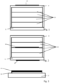
- FIG. 1 shows a schematic view of an oil-water heat exchanger (as it is used in detail, for example, as in EP 2 466 241 A1 described, may be configured) with a plurality of tub elements 10 (soldered together), a base 11 and a cover 12. On the cover 12, an electrical heating coating 13 is arranged.
- two electrical heating coatings 13 are provided, namely on the base 11 on the one hand and between two tub elements 10 on the other.
- Other embodiments are conceivable, e.g. heating coatings on the cover and base or only inside the heat exchanger, possibly between two tubs 10.
- FIG. 3 shows a schematic representation of the electrical heating coating on a substrate, specifically (for example) the cover 12.
- the cover 12 is first produced with a passivation layer (by oxidizing or anodizing).
- the electrical heating coating 13 is then applied to the insulating layer 14, for example (thermally) sprayed on.
Landscapes
- Engineering & Computer Science (AREA)
- Mechanical Engineering (AREA)
- Chemical & Material Sciences (AREA)
- General Engineering & Computer Science (AREA)
- Physics & Mathematics (AREA)
- Thermal Sciences (AREA)
- Combustion & Propulsion (AREA)
- Plasma & Fusion (AREA)
- Materials Engineering (AREA)
- Metallurgy (AREA)
- Organic Chemistry (AREA)
- Chemical Kinetics & Catalysis (AREA)
- Heat-Exchange Devices With Radiators And Conduit Assemblies (AREA)
- Paints Or Removers (AREA)
- Lubrication Of Internal Combustion Engines (AREA)
Claims (11)
- Échangeur de chaleur huile-eau, destiné en particulier au raccordement à un moteur à combustion interne d'un véhicule automobile, comprenant au moins un revêtement chauffant électrique (13) qui est appliqué sur une face externe et/ou à l'intérieur de l'échangeur de chaleur,
caractérisé en ce que
le revêtement chauffant (13) est disposé sur un couvercle (12) d'échangeur de chaleur de l'échangeur de chaleur huile-eau. - Échangeur de chaleur huile-eau selon la revendication 1,
caractérisé en ce que
le revêtement chauffant (13) est appliqué directement sur l'échangeur de chaleur huile-eau, ou est appliqué indirectement, par l'intermédiaire d'une couche isolante (14), sur l'échangeur de chaleur huile-eau, la couche isolante (14) étant fournie de préférence par passivation, en particulier oxydation ou anodisation, du support. - Échangeur de chaleur huile-eau selon la revendication 1 ou 2,
caractérisé en ce que
le revêtement chauffant (13) est mis en place pour le fonctionnement dans la plage de basses tensions, en particulier pour 12 volts, 24 volts ou 48 volts. - Échangeur de chaleur huile-eau selon l'une quelconque des revendications précédentes,
caractérisé en ce que
le revêtement chauffant (13) est configuré sous forme de couche continue, de préférence appliquée par pulvérisation thermique. - Échangeur de chaleur huile-eau selon l'une quelconque des revendications précédentes,
caractérisé en ce que
le revêtement chauffant (13) est configuré sous forme de couche structurée, le revêtement chauffant (13) étant de préférence structuré par un procédé de masquage. - Échangeur de chaleur huile-eau selon l'une quelconque des revendications précédentes,
caractérisé en ce quele revêtement chauffant (13) a de préférence une épaisseur d'au moins 5 µm, encore mieux d'au moins 10 µm et/ou d'au maximum 30 µm, de préférence d'au maximum 20 µm et/ouest une piste conductrice d'au moins 3 mm, de préférence d'au moins 10 mm, encore mieux d'au moins 30 mm de largeur, définie par le revêtement chauffant (13). - Échangeur de chaleur huile-eau selon l'une quelconque des revendications précédentes,
caractérisé en ce que
sur le revêtement chauffant (13) est appliqué un revêtement de protection ou le revêtement chauffant (13) définit une face externe de l'échangeur de chaleur huile-eau. - Échangeur de chaleur huile-eau selon l'une quelconque des revendications précédentes,
caractérisé en ce que
l'échangeur de chaleur huile-eau comporte plusieurs modules, en particulier plusieurs éléments de carter, au moins un revêtement chauffant (13) étant disposé entre deux modules, en particulier éléments de carter. - Échangeur de chaleur huile-eau selon l'une quelconque des revendications précédentes,
caractérisé en ce
qu'est prévu un turbulateur muni d'un revêtement chauffant électrique (13). - Procédé pour la fabrication d'un échangeur de chaleur huile-eau selon l'une quelconque des revendications précédentes, comprenant les étapes :disposition d'un échangeur de chaleur huile-eau etapplication d'un revêtement chauffant électrique (13) sur un couvercle (12) d'échangeur de chaleur de l'échangeur de chaleur huile-eau.
- Utilisation d'un échangeur de chaleur huile-eau selon l'une quelconque des revendications 1 à 9 ou fabriqué selon la revendication 10, en tant qu'échangeur de chaleur huile-eau dans un véhicule automobile, en particulier pour le moteur à combustion interne d'un véhicule automobile.
Applications Claiming Priority (2)
| Application Number | Priority Date | Filing Date | Title |
|---|---|---|---|
| DE102016102890.8A DE102016102890A1 (de) | 2016-02-18 | 2016-02-18 | Öl-Wasser-Wärmetauscher, insbesondere für den Verbrennungsmotor eines Kraftfahrzeuges |
| PCT/EP2017/053111 WO2017140606A1 (fr) | 2016-02-18 | 2017-02-13 | Échangeur de chaleur huile-eau, en particulier pour moteur à combustion interne d'un véhicule automobile |
Publications (2)
| Publication Number | Publication Date |
|---|---|
| EP3417210A1 EP3417210A1 (fr) | 2018-12-26 |
| EP3417210B1 true EP3417210B1 (fr) | 2023-08-16 |
Family
ID=58044061
Family Applications (1)
| Application Number | Title | Priority Date | Filing Date |
|---|---|---|---|
| EP17705097.8A Active EP3417210B1 (fr) | 2016-02-18 | 2017-02-13 | Échangeur de chaleur huile-eau, en particulier pour moteur à combustion interne d'un véhicule automobile |
Country Status (7)
| Country | Link |
|---|---|
| US (1) | US20210219388A1 (fr) |
| EP (1) | EP3417210B1 (fr) |
| JP (1) | JP6925354B2 (fr) |
| KR (2) | KR20180112835A (fr) |
| CN (1) | CN108700333A (fr) |
| DE (1) | DE102016102890A1 (fr) |
| WO (1) | WO2017140606A1 (fr) |
Families Citing this family (4)
| Publication number | Priority date | Publication date | Assignee | Title |
|---|---|---|---|---|
| US12181227B2 (en) | 2018-03-07 | 2024-12-31 | Dana Canada Corporation | Heat exchangers with integrated electrical heating elements and with multiple fluid flow passages |
| CN110357296A (zh) * | 2019-06-28 | 2019-10-22 | 郑州职业技术学院 | 一种公共浴池热水回收过滤利用装置 |
| FR3102550A1 (fr) * | 2019-10-29 | 2021-04-30 | Valeo Systemes Thermiques | Échangeur de chaleur à plaques comprenant un élément électrique chauffant |
| DE102024126997A1 (de) | 2024-09-19 | 2026-03-19 | Bayerische Motoren Werke Aktiengesellschaft | Wärmeübertragereinrichtung für eine Kraftfahrzeugkomponente eines Kraftfahrzeugs, Kraftfahrzeugkomponente für ein Kraftfahrzeug und Wärmeübertragereinrichtung für ein Kraftfahrzeug mit einer Wärmeübertragereinrichtung und/oder mit einer Kraftfahrzeugkomponente |
Family Cites Families (14)
| Publication number | Priority date | Publication date | Assignee | Title |
|---|---|---|---|---|
| DE8907816U1 (de) * | 1989-06-27 | 1989-08-24 | Schmitt, Uwe, 5000 Köln | Ölwanne |
| US5606641A (en) * | 1992-03-27 | 1997-02-25 | Bucaille; Joel | Device for thermal regulation of a circulating fluid comprising a stacked corrugated plate heat exchanger with heat transfer and cooling paths and electrical heating element therebetween |
| DE19823254C5 (de) * | 1998-05-26 | 2007-10-18 | Daimlerchrysler Ag | Brennkraftmaschine |
| SE516844C3 (sv) * | 2000-07-07 | 2002-04-17 | Alfa Laval Ab | Plattvärme/plattvärmeväxlare med elektriskt uppvärmbara skikt i dubbelväggiga plattelement |
| DE102007055496A1 (de) * | 2007-11-21 | 2009-01-29 | Daimler Ag | Baugruppe eines Kraftfahrzeugs |
| EP2428746B8 (fr) * | 2010-09-13 | 2021-12-29 | MAHLE Behr GmbH & Co. KG | Echangeur de chaleur |
| DE102010063141A1 (de) | 2010-12-15 | 2012-06-21 | Mahle International Gmbh | Wärmetauscher |
| DE102011003296A1 (de) * | 2011-01-28 | 2012-08-02 | Behr Gmbh & Co. Kg | Wärmeübertrager |
| DE102011081831A1 (de) | 2011-08-30 | 2013-02-28 | Webasto Ag | Elektrische Heizeinheit, Heizvorrichtung für ein Fahrzeug und Verfahren zur Herstellung einer Heizeinheit |
| DE102011057108A1 (de) * | 2011-12-28 | 2013-07-04 | Webasto Ag | Elektrische Fahrzeugheizvorrichtung mit Wärmeabschirmung |
| DE102012209936A1 (de) | 2012-06-13 | 2013-12-19 | Webasto Ag | Elektrische Heizeinrichtung für ein Kraftfahrzeug |
| DE102013010907A1 (de) * | 2013-06-28 | 2014-12-31 | Webasto SE | Elektrische Heizeinrichtung und Verfahren zur Herstellung einer elektrischen Heizeinrichtung |
| WO2015089671A1 (fr) | 2013-12-19 | 2015-06-25 | Dana Canada Corporation | Échangeur thermique conique |
| FR3026165B1 (fr) * | 2014-09-24 | 2017-06-02 | Commissariat Energie Atomique | Dispositif de traitement thermique d'un fluide a consommation energetique reduite |
-
2016
- 2016-02-18 DE DE102016102890.8A patent/DE102016102890A1/de not_active Withdrawn
-
2017
- 2017-02-13 US US15/999,667 patent/US20210219388A1/en not_active Abandoned
- 2017-02-13 JP JP2018542162A patent/JP6925354B2/ja active Active
- 2017-02-13 KR KR1020187026345A patent/KR20180112835A/ko not_active Ceased
- 2017-02-13 CN CN201780011986.4A patent/CN108700333A/zh active Pending
- 2017-02-13 KR KR1020207014596A patent/KR20200058609A/ko not_active Ceased
- 2017-02-13 EP EP17705097.8A patent/EP3417210B1/fr active Active
- 2017-02-13 WO PCT/EP2017/053111 patent/WO2017140606A1/fr not_active Ceased
Also Published As
| Publication number | Publication date |
|---|---|
| CN108700333A (zh) | 2018-10-23 |
| KR20180112835A (ko) | 2018-10-12 |
| WO2017140606A1 (fr) | 2017-08-24 |
| JP2019512060A (ja) | 2019-05-09 |
| DE102016102890A1 (de) | 2017-08-24 |
| JP6925354B2 (ja) | 2021-08-25 |
| US20210219388A1 (en) | 2021-07-15 |
| KR20200058609A (ko) | 2020-05-27 |
| EP3417210A1 (fr) | 2018-12-26 |
Similar Documents
| Publication | Publication Date | Title |
|---|---|---|
| EP3101999B1 (fr) | Élement de chauffage a coefficient de temperature positif (ctp) et dispositif de chauffage electrique pour un vehicule automobile comprenant un tel element de chauffage ctp | |
| EP4032369B1 (fr) | Carte de circuit imprimé et dispositif de chauffage de fluide | |
| EP3305016B1 (fr) | Dispositif de chauffage pour applications mobiles | |
| EP3417210B1 (fr) | Échangeur de chaleur huile-eau, en particulier pour moteur à combustion interne d'un véhicule automobile | |
| WO2013186106A1 (fr) | Dispositif de chauffage électrique pour un véhicule a moteur | |
| EP3417227B1 (fr) | Échangeur de chaleur, en particulier échangeur de chaleur eau-air ou échangeur de chaleur huile-eau | |
| DE102018215398A1 (de) | Elektrische Heizeinrichtung | |
| DE102019208130A1 (de) | PTC-Heizelement und eine elektrische Heizvorrichtung | |
| EP3305017B1 (fr) | Dispositif de chauffage pour applications mobiles | |
| EP3494294B1 (fr) | Corps alvéolaire pouvant être chauffé électriquement pour le traitement des gaz d'échappement comportant une pluralité d'éléments chauffants | |
| DE102016118829A1 (de) | Elektrische Heizeinrichtung für mobile Anwendungen | |
| DE102022205703A1 (de) | Elektrische Heizeinrichtung für ein Heizsystem | |
| EP3417673B1 (fr) | Système d'échangeur de chaleur | |
| AT522500A1 (de) | Spiralwärmetauscher | |
| DE102011089891B4 (de) | Schaltungsträger und Verfahren zur Herstellung von einem Schaltungsträger, Schaltungsanordnung mit einem Schaltungsträger | |
| EP3459110B1 (fr) | Unité de boîte de refroidissement et système électronique de puissance doté d'une unité de boîte de refroidissement | |
| DE202018102013U1 (de) | Elektrische Heizeinrichtung für mobile Anwendungen | |
| EP4049511B1 (fr) | Dispositif de chauffage électrique, notamment pour des applications mobiles | |
| WO2018153590A1 (fr) | Module semi-conducteur pourvu d'un dissipateur thermique | |
| DE2912000A1 (de) | Vorrichtung zum vorwaermen von heizoel | |
| EP3353475A1 (fr) | Échangeur de chaleur et dispositif de chauffage de véhicule équipé d'un échangeur de chaleur | |
| DE102020128729A1 (de) | Anordnung zum Austauschen von Wärme | |
| DE102015003226A1 (de) | Leiterplattenanordnung für eine Wandlereinrichtung eines Kraftfahrzeugs und Bauelement mit einer Leiterplattenanordnung | |
| DE2055551B2 (de) | Elektrothermische waermepumpe |
Legal Events
| Date | Code | Title | Description |
|---|---|---|---|
| STAA | Information on the status of an ep patent application or granted ep patent |
Free format text: STATUS: UNKNOWN |
|
| STAA | Information on the status of an ep patent application or granted ep patent |
Free format text: STATUS: THE INTERNATIONAL PUBLICATION HAS BEEN MADE |
|
| PUAI | Public reference made under article 153(3) epc to a published international application that has entered the european phase |
Free format text: ORIGINAL CODE: 0009012 |
|
| STAA | Information on the status of an ep patent application or granted ep patent |
Free format text: STATUS: REQUEST FOR EXAMINATION WAS MADE |
|
| 17P | Request for examination filed |
Effective date: 20180807 |
|
| AK | Designated contracting states |
Kind code of ref document: A1 Designated state(s): AL AT BE BG CH CY CZ DE DK EE ES FI FR GB GR HR HU IE IS IT LI LT LU LV MC MK MT NL NO PL PT RO RS SE SI SK SM TR |
|
| AX | Request for extension of the european patent |
Extension state: BA ME |
|
| DAV | Request for validation of the european patent (deleted) | ||
| DAX | Request for extension of the european patent (deleted) | ||
| STAA | Information on the status of an ep patent application or granted ep patent |
Free format text: STATUS: EXAMINATION IS IN PROGRESS |
|
| 17Q | First examination report despatched |
Effective date: 20211207 |
|
| GRAP | Despatch of communication of intention to grant a patent |
Free format text: ORIGINAL CODE: EPIDOSNIGR1 |
|
| STAA | Information on the status of an ep patent application or granted ep patent |
Free format text: STATUS: GRANT OF PATENT IS INTENDED |
|
| INTG | Intention to grant announced |
Effective date: 20221209 |
|
| GRAJ | Information related to disapproval of communication of intention to grant by the applicant or resumption of examination proceedings by the epo deleted |
Free format text: ORIGINAL CODE: EPIDOSDIGR1 |
|
| STAA | Information on the status of an ep patent application or granted ep patent |
Free format text: STATUS: EXAMINATION IS IN PROGRESS |
|
| INTC | Intention to grant announced (deleted) | ||
| GRAP | Despatch of communication of intention to grant a patent |
Free format text: ORIGINAL CODE: EPIDOSNIGR1 |
|
| STAA | Information on the status of an ep patent application or granted ep patent |
Free format text: STATUS: GRANT OF PATENT IS INTENDED |
|
| INTG | Intention to grant announced |
Effective date: 20230516 |
|
| GRAS | Grant fee paid |
Free format text: ORIGINAL CODE: EPIDOSNIGR3 |
|
| GRAA | (expected) grant |
Free format text: ORIGINAL CODE: 0009210 |
|
| STAA | Information on the status of an ep patent application or granted ep patent |
Free format text: STATUS: THE PATENT HAS BEEN GRANTED |
|
| AK | Designated contracting states |
Kind code of ref document: B1 Designated state(s): AL AT BE BG CH CY CZ DE DK EE ES FI FR GB GR HR HU IE IS IT LI LT LU LV MC MK MT NL NO PL PT RO RS SE SI SK SM TR |
|
| REG | Reference to a national code |
Ref country code: GB Ref legal event code: FG4D Free format text: NOT ENGLISH |
|
| REG | Reference to a national code |
Ref country code: CH Ref legal event code: EP |
|
| REG | Reference to a national code |
Ref country code: DE Ref legal event code: R096 Ref document number: 502017015225 Country of ref document: DE |
|
| REG | Reference to a national code |
Ref country code: IE Ref legal event code: FG4D Free format text: LANGUAGE OF EP DOCUMENT: GERMAN |
|
| REG | Reference to a national code |
Ref country code: LT Ref legal event code: MG9D |
|
| REG | Reference to a national code |
Ref country code: NL Ref legal event code: MP Effective date: 20230816 |
|
| PG25 | Lapsed in a contracting state [announced via postgrant information from national office to epo] |
Ref country code: GR Free format text: LAPSE BECAUSE OF FAILURE TO SUBMIT A TRANSLATION OF THE DESCRIPTION OR TO PAY THE FEE WITHIN THE PRESCRIBED TIME-LIMIT Effective date: 20231117 |
|
| PG25 | Lapsed in a contracting state [announced via postgrant information from national office to epo] |
Ref country code: IS Free format text: LAPSE BECAUSE OF FAILURE TO SUBMIT A TRANSLATION OF THE DESCRIPTION OR TO PAY THE FEE WITHIN THE PRESCRIBED TIME-LIMIT Effective date: 20231216 |
|
| PG25 | Lapsed in a contracting state [announced via postgrant information from national office to epo] |
Ref country code: SE Free format text: LAPSE BECAUSE OF FAILURE TO SUBMIT A TRANSLATION OF THE DESCRIPTION OR TO PAY THE FEE WITHIN THE PRESCRIBED TIME-LIMIT Effective date: 20230816 Ref country code: RS Free format text: LAPSE BECAUSE OF FAILURE TO SUBMIT A TRANSLATION OF THE DESCRIPTION OR TO PAY THE FEE WITHIN THE PRESCRIBED TIME-LIMIT Effective date: 20230816 Ref country code: PT Free format text: LAPSE BECAUSE OF FAILURE TO SUBMIT A TRANSLATION OF THE DESCRIPTION OR TO PAY THE FEE WITHIN THE PRESCRIBED TIME-LIMIT Effective date: 20231218 Ref country code: NO Free format text: LAPSE BECAUSE OF FAILURE TO SUBMIT A TRANSLATION OF THE DESCRIPTION OR TO PAY THE FEE WITHIN THE PRESCRIBED TIME-LIMIT Effective date: 20231116 Ref country code: NL Free format text: LAPSE BECAUSE OF FAILURE TO SUBMIT A TRANSLATION OF THE DESCRIPTION OR TO PAY THE FEE WITHIN THE PRESCRIBED TIME-LIMIT Effective date: 20230816 Ref country code: LV Free format text: LAPSE BECAUSE OF FAILURE TO SUBMIT A TRANSLATION OF THE DESCRIPTION OR TO PAY THE FEE WITHIN THE PRESCRIBED TIME-LIMIT Effective date: 20230816 Ref country code: LT Free format text: LAPSE BECAUSE OF FAILURE TO SUBMIT A TRANSLATION OF THE DESCRIPTION OR TO PAY THE FEE WITHIN THE PRESCRIBED TIME-LIMIT Effective date: 20230816 Ref country code: IS Free format text: LAPSE BECAUSE OF FAILURE TO SUBMIT A TRANSLATION OF THE DESCRIPTION OR TO PAY THE FEE WITHIN THE PRESCRIBED TIME-LIMIT Effective date: 20231216 Ref country code: HR Free format text: LAPSE BECAUSE OF FAILURE TO SUBMIT A TRANSLATION OF THE DESCRIPTION OR TO PAY THE FEE WITHIN THE PRESCRIBED TIME-LIMIT Effective date: 20230816 Ref country code: GR Free format text: LAPSE BECAUSE OF FAILURE TO SUBMIT A TRANSLATION OF THE DESCRIPTION OR TO PAY THE FEE WITHIN THE PRESCRIBED TIME-LIMIT Effective date: 20231117 Ref country code: FI Free format text: LAPSE BECAUSE OF FAILURE TO SUBMIT A TRANSLATION OF THE DESCRIPTION OR TO PAY THE FEE WITHIN THE PRESCRIBED TIME-LIMIT Effective date: 20230816 |
|
| PG25 | Lapsed in a contracting state [announced via postgrant information from national office to epo] |
Ref country code: PL Free format text: LAPSE BECAUSE OF FAILURE TO SUBMIT A TRANSLATION OF THE DESCRIPTION OR TO PAY THE FEE WITHIN THE PRESCRIBED TIME-LIMIT Effective date: 20230816 |
|
| PG25 | Lapsed in a contracting state [announced via postgrant information from national office to epo] |
Ref country code: ES Free format text: LAPSE BECAUSE OF FAILURE TO SUBMIT A TRANSLATION OF THE DESCRIPTION OR TO PAY THE FEE WITHIN THE PRESCRIBED TIME-LIMIT Effective date: 20230816 |
|
| PG25 | Lapsed in a contracting state [announced via postgrant information from national office to epo] |
Ref country code: SM Free format text: LAPSE BECAUSE OF FAILURE TO SUBMIT A TRANSLATION OF THE DESCRIPTION OR TO PAY THE FEE WITHIN THE PRESCRIBED TIME-LIMIT Effective date: 20230816 Ref country code: RO Free format text: LAPSE BECAUSE OF FAILURE TO SUBMIT A TRANSLATION OF THE DESCRIPTION OR TO PAY THE FEE WITHIN THE PRESCRIBED TIME-LIMIT Effective date: 20230816 Ref country code: ES Free format text: LAPSE BECAUSE OF FAILURE TO SUBMIT A TRANSLATION OF THE DESCRIPTION OR TO PAY THE FEE WITHIN THE PRESCRIBED TIME-LIMIT Effective date: 20230816 Ref country code: EE Free format text: LAPSE BECAUSE OF FAILURE TO SUBMIT A TRANSLATION OF THE DESCRIPTION OR TO PAY THE FEE WITHIN THE PRESCRIBED TIME-LIMIT Effective date: 20230816 Ref country code: DK Free format text: LAPSE BECAUSE OF FAILURE TO SUBMIT A TRANSLATION OF THE DESCRIPTION OR TO PAY THE FEE WITHIN THE PRESCRIBED TIME-LIMIT Effective date: 20230816 Ref country code: CZ Free format text: LAPSE BECAUSE OF FAILURE TO SUBMIT A TRANSLATION OF THE DESCRIPTION OR TO PAY THE FEE WITHIN THE PRESCRIBED TIME-LIMIT Effective date: 20230816 Ref country code: SK Free format text: LAPSE BECAUSE OF FAILURE TO SUBMIT A TRANSLATION OF THE DESCRIPTION OR TO PAY THE FEE WITHIN THE PRESCRIBED TIME-LIMIT Effective date: 20230816 |
|
| REG | Reference to a national code |
Ref country code: DE Ref legal event code: R097 Ref document number: 502017015225 Country of ref document: DE |
|
| PLBE | No opposition filed within time limit |
Free format text: ORIGINAL CODE: 0009261 |
|
| STAA | Information on the status of an ep patent application or granted ep patent |
Free format text: STATUS: NO OPPOSITION FILED WITHIN TIME LIMIT |
|
| 26N | No opposition filed |
Effective date: 20240517 |
|
| PG25 | Lapsed in a contracting state [announced via postgrant information from national office to epo] |
Ref country code: IT Free format text: LAPSE BECAUSE OF FAILURE TO SUBMIT A TRANSLATION OF THE DESCRIPTION OR TO PAY THE FEE WITHIN THE PRESCRIBED TIME-LIMIT Effective date: 20230816 Ref country code: SI Free format text: LAPSE BECAUSE OF FAILURE TO SUBMIT A TRANSLATION OF THE DESCRIPTION OR TO PAY THE FEE WITHIN THE PRESCRIBED TIME-LIMIT Effective date: 20230816 |
|
| PG25 | Lapsed in a contracting state [announced via postgrant information from national office to epo] |
Ref country code: MC Free format text: LAPSE BECAUSE OF FAILURE TO SUBMIT A TRANSLATION OF THE DESCRIPTION OR TO PAY THE FEE WITHIN THE PRESCRIBED TIME-LIMIT Effective date: 20230816 |
|
| REG | Reference to a national code |
Ref country code: CH Ref legal event code: PL |
|
| PG25 | Lapsed in a contracting state [announced via postgrant information from national office to epo] |
Ref country code: LU Free format text: LAPSE BECAUSE OF NON-PAYMENT OF DUE FEES Effective date: 20240213 |
|
| PG25 | Lapsed in a contracting state [announced via postgrant information from national office to epo] |
Ref country code: CH Free format text: LAPSE BECAUSE OF NON-PAYMENT OF DUE FEES Effective date: 20240229 |
|
| PG25 | Lapsed in a contracting state [announced via postgrant information from national office to epo] |
Ref country code: LU Free format text: LAPSE BECAUSE OF NON-PAYMENT OF DUE FEES Effective date: 20240213 Ref country code: CH Free format text: LAPSE BECAUSE OF NON-PAYMENT OF DUE FEES Effective date: 20240229 |
|
| PG25 | Lapsed in a contracting state [announced via postgrant information from national office to epo] |
Ref country code: BG Free format text: LAPSE BECAUSE OF FAILURE TO SUBMIT A TRANSLATION OF THE DESCRIPTION OR TO PAY THE FEE WITHIN THE PRESCRIBED TIME-LIMIT Effective date: 20230816 |
|
| PG25 | Lapsed in a contracting state [announced via postgrant information from national office to epo] |
Ref country code: BG Free format text: LAPSE BECAUSE OF FAILURE TO SUBMIT A TRANSLATION OF THE DESCRIPTION OR TO PAY THE FEE WITHIN THE PRESCRIBED TIME-LIMIT Effective date: 20230816 |
|
| REG | Reference to a national code |
Ref country code: BE Ref legal event code: MM Effective date: 20240229 |
|
| PG25 | Lapsed in a contracting state [announced via postgrant information from national office to epo] |
Ref country code: BE Free format text: LAPSE BECAUSE OF NON-PAYMENT OF DUE FEES Effective date: 20240229 |
|
| PG25 | Lapsed in a contracting state [announced via postgrant information from national office to epo] |
Ref country code: IE Free format text: LAPSE BECAUSE OF NON-PAYMENT OF DUE FEES Effective date: 20240213 |
|
| PG25 | Lapsed in a contracting state [announced via postgrant information from national office to epo] |
Ref country code: IE Free format text: LAPSE BECAUSE OF NON-PAYMENT OF DUE FEES Effective date: 20240213 Ref country code: BE Free format text: LAPSE BECAUSE OF NON-PAYMENT OF DUE FEES Effective date: 20240229 |
|
| REG | Reference to a national code |
Ref country code: AT Ref legal event code: MM01 Ref document number: 1600404 Country of ref document: AT Kind code of ref document: T Effective date: 20240213 |
|
| PG25 | Lapsed in a contracting state [announced via postgrant information from national office to epo] |
Ref country code: AT Free format text: LAPSE BECAUSE OF NON-PAYMENT OF DUE FEES Effective date: 20240213 |
|
| PG25 | Lapsed in a contracting state [announced via postgrant information from national office to epo] |
Ref country code: CY Free format text: LAPSE BECAUSE OF FAILURE TO SUBMIT A TRANSLATION OF THE DESCRIPTION OR TO PAY THE FEE WITHIN THE PRESCRIBED TIME-LIMIT; INVALID AB INITIO Effective date: 20170213 |
|
| PG25 | Lapsed in a contracting state [announced via postgrant information from national office to epo] |
Ref country code: HU Free format text: LAPSE BECAUSE OF FAILURE TO SUBMIT A TRANSLATION OF THE DESCRIPTION OR TO PAY THE FEE WITHIN THE PRESCRIBED TIME-LIMIT; INVALID AB INITIO Effective date: 20170213 |
|
| PG25 | Lapsed in a contracting state [announced via postgrant information from national office to epo] |
Ref country code: TR Free format text: LAPSE BECAUSE OF FAILURE TO SUBMIT A TRANSLATION OF THE DESCRIPTION OR TO PAY THE FEE WITHIN THE PRESCRIBED TIME-LIMIT Effective date: 20230816 |
|
| REG | Reference to a national code |
Ref country code: DE Ref legal event code: R082 Ref document number: 502017015225 Country of ref document: DE Representative=s name: PUSCHMANN BORCHERT KAISER KLETTNER PATENTANWAE, DE Ref country code: DE Ref legal event code: R082 Ref document number: 502017015225 Country of ref document: DE Representative=s name: PATCARE PATENTANWAELTE PARTNERSCHAFT MBB, DE |
|
| PGFP | Annual fee paid to national office [announced via postgrant information from national office to epo] |
Ref country code: GB Payment date: 20260219 Year of fee payment: 10 |
|
| PGFP | Annual fee paid to national office [announced via postgrant information from national office to epo] |
Ref country code: DE Payment date: 20260217 Year of fee payment: 10 |
|
| PGFP | Annual fee paid to national office [announced via postgrant information from national office to epo] |
Ref country code: FR Payment date: 20260223 Year of fee payment: 10 |