EP1674261A2 - Système de nettoyage pour une machine à imprimer - Google Patents
Système de nettoyage pour une machine à imprimer Download PDFInfo
- Publication number
- EP1674261A2 EP1674261A2 EP05019330A EP05019330A EP1674261A2 EP 1674261 A2 EP1674261 A2 EP 1674261A2 EP 05019330 A EP05019330 A EP 05019330A EP 05019330 A EP05019330 A EP 05019330A EP 1674261 A2 EP1674261 A2 EP 1674261A2
- Authority
- EP
- European Patent Office
- Prior art keywords
- cleaning
- liquid
- valve
- devices
- cleaning device
- Prior art date
- Legal status (The legal status is an assumption and is not a legal conclusion. Google has not performed a legal analysis and makes no representation as to the accuracy of the status listed.)
- Withdrawn
Links
Images

Classifications
-
- B—PERFORMING OPERATIONS; TRANSPORTING
- B41—PRINTING; LINING MACHINES; TYPEWRITERS; STAMPS
- B41F—PRINTING MACHINES OR PRESSES
- B41F35/00—Cleaning arrangements or devices
- B41F35/04—Cleaning arrangements or devices for inking rollers
-
- B—PERFORMING OPERATIONS; TRANSPORTING
- B08—CLEANING
- B08B—CLEANING IN GENERAL; PREVENTION OF FOULING IN GENERAL
- B08B3/00—Cleaning by methods involving the use or presence of liquid or steam
- B08B3/02—Cleaning by the force of jets or sprays
- B08B3/022—Cleaning travelling work
-
- B—PERFORMING OPERATIONS; TRANSPORTING
- B08—CLEANING
- B08B—CLEANING IN GENERAL; PREVENTION OF FOULING IN GENERAL
- B08B3/00—Cleaning by methods involving the use or presence of liquid or steam
- B08B3/02—Cleaning by the force of jets or sprays
- B08B3/024—Cleaning by means of spray elements moving over the surface to be cleaned
-
- B—PERFORMING OPERATIONS; TRANSPORTING
- B41—PRINTING; LINING MACHINES; TYPEWRITERS; STAMPS
- B41F—PRINTING MACHINES OR PRESSES
- B41F35/00—Cleaning arrangements or devices
-
- B—PERFORMING OPERATIONS; TRANSPORTING
- B41—PRINTING; LINING MACHINES; TYPEWRITERS; STAMPS
- B41F—PRINTING MACHINES OR PRESSES
- B41F35/00—Cleaning arrangements or devices
- B41F35/06—Cleaning arrangements or devices for offset cylinders
-
- B—PERFORMING OPERATIONS; TRANSPORTING
- B41—PRINTING; LINING MACHINES; TYPEWRITERS; STAMPS
- B41P—INDEXING SCHEME RELATING TO PRINTING, LINING MACHINES, TYPEWRITERS, AND TO STAMPS
- B41P2235/00—Cleaning
- B41P2235/10—Cleaning characterised by the methods or devices
- B41P2235/26—Spraying devices
Definitions
- the present invention relates to a cleaning system for a printing machine with at least one cleaning device for cleaning of rotational bodies, in particular of cylinders and rollers, of printing presses.
- a particular field of application of the invention are offset printing machines.
- a cleaning system of this type is known from DE 20 2004 006 534 U1.
- the metering valves for the cleaning liquid are arranged in the liquid supply cabinet. Consequently, the fluid line lengths between the metering valves and the liquid dispensers of the cleaning device are dependent on the distance of the cleaning device from the liquid supply cabinet. Therefore, in the prior art, the metering parameters, in particular the opening time of the valves for each cleaning device at each printing unit are different and must be determined empirically.
- the dosing parameters are particularly influenced by the different liquid masses in the lines, which are used to dispense liquid have to be accelerated.
- the metering parameters are particularly dependent on the viscosities of the individual liquids.
- the problem to be solved is to simplify the setting of parameters relating to a liquid dispensing by a cleaning device.
- valve device of each of the cleaning devices is arranged on the printing unit, which is also associated with the cleaning device, at least approximately equal conditions for the supply of cleaning fluid created for all printing units, in particular approximately equal liquid line lengths or fluid line lengths created by the valve device to the cleaning device.
- the valve opening times of the valve device for any number of cleaning devices can be adjusted to the same fluid line lengths.
- compressed air lines for embodiments in which the liquid is expelled from the cleaning device by means of compressed air.
- a fluid may be, for example, liquid, compressed air or liquid mixed with compressed air.
- the invention also achieves more stable flow conditions and more stable pressure conditions. In particular, there are fewer deviations in the flow conditions and pressure ratios from printing unit to printing unit at the corresponding liquid dispensing devices of the cleaning devices. By the invention, a more uniform distribution of liquid is achieved in all printing units of a printing press.
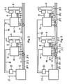
- FIG. 1 shows a cleaning system 2 for a printing press, which has one or more printing units 4, of which in Fig. 1, a printing unit 4 and in Fig. 2 and in Fig. 3 are each two printing units 4 are shown.
- the cleaning system 2 contains at least one cleaning device 6.
- Each of the printing units 4 is associated with at least one cleaning device 6 for cleaning at least one rotary body, such as a cylinder or a roller, the printing unit 4.
- the cleaning device 6, a device with a moistened wash cloth, z , B. for cleaning a blanket cylinder; or a paint roller washing device with a spraying device for spraying liquid onto an inking roller.
- Each cleaning device 6 has at least one liquid dispensing device 8 and at least one valve device 10 for dispensing liquid into a fluid line 12, for example three valve devices 10 as shown.
- Each of the valve devices 10 is controllable and has its associated fluid line 12 with its associated liquid dispenser 8 fluidly connected.
- the at least one valve device 10 is preferably designed as a liquid valve.
- a liquid to be metered by the valve device 10 can be any liquid used in the cleaning of rotary bodies of a printing machine, for example water, with or without further additives, washing liquid for washing normal printing ink or UV washing liquid for washing UV curable printing ink.
- the liquid dispensing device 8 has at least one, preferably a plurality, over the length of the cylinder to be cleaned or the ink roller to be cleaned liquid discharge openings, for example spray nozzles.
- the liquid dispensing device 8 can deliver liquid in a known manner, for example to a washing cloth, which is placed against a rotary body for its cleaning, or onto a rotary body of the printing unit 4.
- a liquid dispenser 8 is preferably a part of the corresponding cleaning device 6.
- valve devices 10 of each cleaning device 6 are arranged on a printing unit side wall of the relevant printing unit 4, to which the cleaning device 6 is assigned. In this way, the fluid lines 12 can be made short and approximately equal in length. Preferably, each of the valve devices 10 is located close to that cleaning device 6, to which it is connected via the corresponding fluid line 12.
- each valve device 10 preferably also performs the function of a check valve in addition to its metering function, wherein after metering the liquid in question in the fluid line 12, the valve device 10 is closed and thus a backflow of the liquid is prevented.
- the conventional check valves close to the cleaning device 6 can be dispensed with.
- valve devices 10 For each cleaning device 6, for example, a certain number of valve devices 10 may be provided, corresponding to the number of different liquids. For example, three valve devices 10 may be provided for each cleaning device 6, of which, for example, a first valve device 10-1 for water, a second valve device 10-2 for washing liquid and a third valve device 10-3 for UV washing liquid may be provided.
- At least one of the at least one cleaning device 6 is an inking roller cleaning device 6-1, which is assigned to an inking unit of the printing unit 4.
- each printing unit 4 has at least one inking unit cleaning device 6-1.
- each valve device 10-1, 10-2, 10-3 of the ink fountain roller cleaning device 6-1 is preferably connected in each case a separate fluid line 12-1, 12-2, 12-3, for example, as shown for the ink fountain roller cleaning device, a first Fluid line 12-1 for water, a second fluid line 12-2 for washing liquid and a third fluid line 12-3 for UV washing liquid.
- a separate fluid line 12-1, 12-2, 12-3 for each liquid is required in particular when the liquid discharged from the valve device 10 through the fluid line 12 and the liquid dispenser 8 is not discharged from the fluid line 12 and from the liquid dispenser 8 by means of compressed air is blown, but a certain amount of liquid already present in the fluid line 12 is conveyed by additionally metered liquid supplied to the associated liquid dispensing device 8 and is sprayed out of the liquid dispensing device 8.
- each fluid line 12-1, 12-2, 12-3 may be associated with a corresponding fluid dispenser 8-1, 8-2, 8-3, for example in the form of a spray tube.
- the ink fountain roller cleaning device can in known form a doctor or other suitable element for removing paint, paper particles and introduced with the liquid discharge device 8 in the inking liquid from one of the rotating body of the inking unit.
- the liquid dispensing devices 8 may be associated with a first body of rotation of the inking unit and the squeegee with another, second body of rotation of the inking unit.
- At least two inking unit cleaning devices 6-1 can be provided, which are each assigned to a different printing unit 4 and of which corresponding fluid lines 12-1, 12-2, 12-3 between the respective liquid dispensing device 8 and the respective valve device 10 are of substantially equal length.
- At least one of the at least one cleaning device 6 may be a blanket cleaning device 6-2.
- a blanket cleaning device 6-2 for example, three valve devices 10 may be provided, which are designed and arranged for dispensing liquid into a common fluid line 12-4.
- the common fluid line 12-4 is fluidly connected to a compressed air connection 14, of which the common fluid line 12-4 by opening a valve 16 in a compressed air line 18, which opens into the common fluid line 12-4, can be acted upon with compressed air, for blowing out the in the common fluid line 12-4 metered liquid.
- the common fluid line 12-4 may be provided for conveying various liquids to a liquid dispensing device 8. In particular, it is possible to alternately pump washing liquid, water and UV washing liquid to the respective liquid dispensing device 8.
- corresponding fluid lines 12-4 are formed between the respective liquid dispensing device 8 and the respective valve device 10, preferably of substantially equal length.
- the corresponding liquid dispensing devices 8 can be operated at different printing units 4 with identical parameters, for example the same opening times of the valve devices 10.
- the corresponding valve devices 10, for example the washing liquid valve devices 10, of each printing unit 4 can be operated with the same control program.
- the term "essentially" means that the line lengths and line cross sections may indeed differ from one another, but not so far that this results in disadvantageous different flow times or volume flow rates in the lines.
- the cleaning devices 6 can be provided and formed on different printing units 4 for cleaning with at least two different liquids, for example as explained above, with three different liquids.
- these at least two cleaning devices 6 each corresponding valve devices 10-1, 10-2, 10-3, which are provided for metering the same liquid on.
- the valve devices 10-1 for water at different printing units 4 are corresponding valve devices.
- the corresponding valve devices 10 is associated with a common feed line 20 for supplying the relevant liquid to the corresponding valve devices 10.
- a first common supply line 20-1 for water, a second common supply line 20-2 for washing liquid and a third common supply line 20-3 for UV washing liquid may be provided.
- valve devices 10 may be fluidly connected in parallel with the corresponding common supply line.
- a line branch 22 may extend from the common feed line 20 to each of the corresponding valve devices 10, for example in the form of a stub line, as shown in FIGS. 1 and 2.
- valve device 10 for example all valve devices 10, are connected in sequence (sequentially) to the common supply line 20, as shown in FIG.
- a portion of the valve devices may be sequentially and a portion of the valve devices in fluid communication with the corresponding common supply line.
- the common supply lines 20 and, if present, the line branches 22 preferably have a larger inner diameter than the fluid lines 12 between the valve devices 10 and their associated liquid dispensing devices 8.
- At least one liquid container 30 is provided for supplying the corresponding valve devices 10 with the corresponding liquid.
- the at least one liquid container 30 for supplying the corresponding valve device 10 with liquid is preferably formed as an intermediate container 32, which receives the liquid in question from a reservoir 34, for example by sucking the liquid from the reservoir 34 into the intermediate container 32.
- a vacuum cleaner 36 be provided for example in the form of an injector or preferably an ejector.
- the vacuum cleaner 36 is preferably operated with compressed air.
- a valve 40 is arranged in a compressed air line 38 from a compressed air connection 37 to the vacuum cleaner 36, which is opened to operate the vacuum cleaner 36.
- a valve 41 is preferably arranged, via which the respective intermediate container 32 can be evacuated, for sucking liquid into the intermediate container 32 from the respective reservoir 34 via a suction line 43rd
- each intermediate container 32 in the illustrated embodiment can be pressurized.
- each intermediate container 32 is connected to a compressed air source, for example the compressed air source 37, via a compressed air line 45, in which a valve 47 is arranged, via which the respective intermediate container 32 is selectively pressurized.
- a valve 49 arranged in each of the suction lines 43 is preferably closed in each case and a valve 51 arranged in each of the common supply lines 20 is opened in order to provide the liquid from the intermediate container 32 to the respective valve devices 10.
- a supply cabinet 42 which comprises the at least one liquid container 30-1, 30-2, 30-3 for each of the various liquids associated with the respective common supply line 20-1, 20-2, 20-3 is connected or connectable.
- the liquid containers may be provided with a feed for liquid from a container or from a fresh water line.
- the at least one valve device 10 for the at least one cleaning device 6 is preferably arranged outside the supply cabinet 42.
- a cleaning device 6 has at least two valve devices 10, for example three valve devices 10, as shown in the drawings, these are preferably at least two valve devices 10 in one Valve assembly 44 is arranged.
- all valve devices 10 of a printing unit 4 are arranged in a single valve arrangement 44.
- the valve arrangement 44 is preferably designed as a valve block.
- valve assembly 44 When the valve assembly 44 has two or more valve devices 10 provided for metering the same liquid, these two or more valve devices 10 are preferably connected to a single common supply line 20 as shown in FIG.
- a single common supply line 20 is provided in each case for all mutually corresponding valve devices 10 of all printing units 4, as shown in FIGS. 1, 2 and 3.
- a control device 50 is provided.
- the control device 50 can be arranged anywhere, for example in the supply cabinet 42.
- the control device 50 is preferably an electronic control device 50.
- the control device 50 can be microprocessor-based.
- the control device 50 for controlling the at least one valve device 10 can be formed in particular by a central control device of the cleaning system.
- the central control device of the cleaning system is also designed to control components of the cleaning system, for example of all components of the cleaning system.
- control device 50 is connected to the components to be controlled via control lines.
- control signals can be transmitted via a suitable bus 46. This significantly reduces the wiring effort.
- a separate fluid line 12 may also be provided for the blanket cleaning device 6 for each liquid, corresponding to the inking unit cleaning device 6.
- a fluid line 12 may be provided for a plurality of liquids, corresponding to the blanket cleaning device 6.
- pressure reducers may be provided in the compressed air lines, for example in the compressed air lines 18, 45.
- printing unit is used here representative of various embodiments and indicates z.
Landscapes
- Inking, Control Or Cleaning Of Printing Machines (AREA)
- Cleaning By Liquid Or Steam (AREA)
Applications Claiming Priority (1)
| Application Number | Priority Date | Filing Date | Title |
|---|---|---|---|
| DE200410063336 DE102004063336A1 (de) | 2004-12-23 | 2004-12-23 | Flüssigkeitsversorgungseinrichtung für eine Druckmaschinen-Reinigungsvorrichtung |
Publications (2)
| Publication Number | Publication Date |
|---|---|
| EP1674261A2 true EP1674261A2 (fr) | 2006-06-28 |
| EP1674261A3 EP1674261A3 (fr) | 2007-09-05 |
Family
ID=35241104
Family Applications (2)
| Application Number | Title | Priority Date | Filing Date |
|---|---|---|---|
| EP05019330A Withdrawn EP1674261A3 (fr) | 2004-12-23 | 2005-09-06 | Système de nettoyage pour une machine à imprimer |
| EP20050022339 Expired - Lifetime EP1674262B1 (fr) | 2004-12-23 | 2005-10-13 | Dispositif d'alimentation en fluide pour un appareil de nettoyage d'une machine à imprimer |
Family Applications After (1)
| Application Number | Title | Priority Date | Filing Date |
|---|---|---|---|
| EP20050022339 Expired - Lifetime EP1674262B1 (fr) | 2004-12-23 | 2005-10-13 | Dispositif d'alimentation en fluide pour un appareil de nettoyage d'une machine à imprimer |
Country Status (2)
| Country | Link |
|---|---|
| EP (2) | EP1674261A3 (fr) |
| DE (2) | DE102004063336A1 (fr) |
Cited By (3)
| Publication number | Priority date | Publication date | Assignee | Title |
|---|---|---|---|---|
| WO2007115739A3 (fr) * | 2006-04-03 | 2007-12-13 | Technotrans Ag | Dispositif de lavage pour presse à imprimer offset |
| DE102007001662B3 (de) * | 2007-01-11 | 2008-07-03 | Technotrans Ag | Vorrichtung zur Versorgung einer Druckmaschine mit Waschflüssigkeit |
| EP2011652A3 (fr) * | 2007-07-03 | 2010-05-26 | technotrans AG | Dispositif de préparation de liquides de nettoyage pour des presses rotatives |
Family Cites Families (9)
| Publication number | Priority date | Publication date | Assignee | Title |
|---|---|---|---|---|
| ATE71584T1 (de) * | 1987-08-17 | 1992-02-15 | Precision Engineered Systems I | Automatisches gummituchwaschsystem mit stroemung durch eine zerstaeuberstange. |
| US5109770A (en) * | 1989-09-22 | 1992-05-05 | Oxy-Dry Corporation | Printing cylinder cleaning system |
| US5213044A (en) * | 1990-11-30 | 1993-05-25 | Como Technologies, Incorporated | Method and apparatus for use in printing |
| DE29715358U1 (de) * | 1997-08-27 | 1997-10-30 | Kba-Planeta Ag, 01445 Radebeul | Einrichtung zum Zuführen eines Reinigungsfluids |
| DE19860855A1 (de) * | 1998-12-31 | 2000-07-06 | Koenig & Bauer Ag | Vorrichtung zum Reinigen einer Walze |
| DE20012101U1 (de) * | 2000-07-12 | 2000-11-16 | Technotrans AG, 48336 Sassenberg | Anordnung zur peripheren Versorgung bzw. Entsorgung von Fluiden bei Druckmaschinen |
| ITGE20020033A1 (it) * | 2002-04-24 | 2003-10-24 | Schiavi Spa | Metodo di lavaggio automatico del circuito di inchiostrazione nelle macchine da stampa rotative, ed impianto per l'attuazione di detto metod |
| DE10313014A1 (de) * | 2003-03-24 | 2004-10-07 | Baldwin Germany Gmbh | Druckmaschinen-Spül- und -entleervorrichtung und Verfahren |
| DE202004001174U1 (de) * | 2004-01-27 | 2004-04-08 | Man Roland Druckmaschinen Ag | Versorgungseinrichtung für eine Reinigungsvorrichtung in einer Verarbeitungsmaschine |
-
2004
- 2004-12-23 DE DE200410063336 patent/DE102004063336A1/de not_active Withdrawn
-
2005
- 2005-09-06 EP EP05019330A patent/EP1674261A3/fr not_active Withdrawn
- 2005-10-13 DE DE200550010792 patent/DE502005010792D1/de not_active Expired - Lifetime
- 2005-10-13 EP EP20050022339 patent/EP1674262B1/fr not_active Expired - Lifetime
Cited By (4)
| Publication number | Priority date | Publication date | Assignee | Title |
|---|---|---|---|---|
| WO2007115739A3 (fr) * | 2006-04-03 | 2007-12-13 | Technotrans Ag | Dispositif de lavage pour presse à imprimer offset |
| DE102007001662B3 (de) * | 2007-01-11 | 2008-07-03 | Technotrans Ag | Vorrichtung zur Versorgung einer Druckmaschine mit Waschflüssigkeit |
| WO2008083947A1 (fr) * | 2007-01-11 | 2008-07-17 | Technotrans Ag | Dispositif d'alimentation d'une machine d'impression en liquide de lavage |
| EP2011652A3 (fr) * | 2007-07-03 | 2010-05-26 | technotrans AG | Dispositif de préparation de liquides de nettoyage pour des presses rotatives |
Also Published As
| Publication number | Publication date |
|---|---|
| DE102004063336A1 (de) | 2006-07-06 |
| EP1674262A3 (fr) | 2007-08-08 |
| EP1674262A2 (fr) | 2006-06-28 |
| EP1674262B1 (fr) | 2011-01-05 |
| EP1674261A3 (fr) | 2007-09-05 |
| DE502005010792D1 (de) | 2011-02-17 |
Similar Documents
| Publication | Publication Date | Title |
|---|---|---|
| DE102004055749B4 (de) | Versorgungseinrichtung für eine Reinigungsvorrichtung in einer Verarbeitungsmaschine | |
| EP0570727B1 (fr) | Dispositif de lavage pour machines à imprimer | |
| EP0754552A1 (fr) | Procédé et dispositif de lavage d'un cylindre de plaque et d'un rouleau d'application dans une machine d'impression | |
| DE29616686U1 (de) | Einrichtung zum Beschichten von Bedruckstoffen mit einer Flüssigkeit | |
| EP0570763B1 (fr) | Dispositif de lavage pour machine à imprimer | |
| EP2001681B1 (fr) | Dispositif de lavage pour presse à imprimer offset | |
| EP1441908B1 (fr) | Procede et dispositif de nettoyage de cylindres d'une presse a imprimer | |
| EP1674261A2 (fr) | Système de nettoyage pour une machine à imprimer | |
| DE102013213059A1 (de) | Vorrichtung und Verfahren zum Aufbringen und Dosieren von Reinigungsflüssigkeit | |
| EP0657282B1 (fr) | Dispositif d'encrage | |
| EP0730527B1 (fr) | Dispositif d'alimentation du mecanisme d'encrage d'imprimantes en encre d'impression | |
| DE10252013B4 (de) | Reinigung von Walzen in Druckmaschinen | |
| DE102005042302A1 (de) | Druckmaschinen-Reinigungsflüssigkeitsversorgungseinrichtung | |
| EP1535737B1 (fr) | Machine d'impression offset avec dispositif de nettoyage pour celle-ci | |
| DE102005008937B4 (de) | Beschichtungseinheit in einer Druckmaschine | |
| DE10232254B4 (de) | Rotationssiebdruckmaschine | |
| DE10101834B4 (de) | Vorrichtung zum Reinigen von Arbeitsflächen | |
| DE102008042741B4 (de) | Reinigungsvorrichtung für einen Zylinder oder eine Walze einer Druckmaschine | |
| EP2008817B1 (fr) | Dispositif d'alimentation automatique en encres d'au moins un élément d'impression d'une imprimante rotative avec coldset et heatset | |
| DE102006014990B4 (de) | Sprühfeuchtwerk für Druckmaschinen und Verfahren zur Reinigung der wenigstens einen Düse eines Sprühfeuchtwerks | |
| DE102004011859A1 (de) | Reinigungsvorrichtung für einen Zylinder oder eine Walze | |
| DE10303608B4 (de) | Verfahren für einen stabilen Maschinenlauf an Druckeinheiten einer Rotationsdruckmaschine für den Betrieb mit teilbreitem Bedruckstoff | |
| DE102006055278B3 (de) | Reinigungsverfahren sowie Reinigungsvorrichtung für eine Zylinderoberfläche einer Druckmaschine | |
| EP1597080A1 (fr) | Dispositif de nettoyage pour elements d'impression et/ou de revetement dans une machine transformatrice | |
| EP1666254B1 (fr) | Dispositif pour l'alimentation en produit de lavage sur la surface d'un rouleau dans une machine d'impression |
Legal Events
| Date | Code | Title | Description |
|---|---|---|---|
| PUAI | Public reference made under article 153(3) epc to a published international application that has entered the european phase |
Free format text: ORIGINAL CODE: 0009012 |
|
| AK | Designated contracting states |
Kind code of ref document: A2 Designated state(s): AT BE BG CH CY CZ DE DK EE ES FI FR GB GR HU IE IS IT LI LT LU LV MC NL PL PT RO SE SI SK TR |
|
| AX | Request for extension of the european patent |
Extension state: AL BA HR MK YU |
|
| RAP1 | Party data changed (applicant data changed or rights of an application transferred) |
Owner name: BALDWIN GERMANY GMBH |
|
| PUAL | Search report despatched |
Free format text: ORIGINAL CODE: 0009013 |
|
| AK | Designated contracting states |
Kind code of ref document: A3 Designated state(s): AT BE BG CH CY CZ DE DK EE ES FI FR GB GR HU IE IS IT LI LT LU LV MC NL PL PT RO SE SI SK TR |
|
| AX | Request for extension of the european patent |
Extension state: AL BA HR MK YU |
|
| RIC1 | Information provided on ipc code assigned before grant |
Ipc: B08B 3/02 20060101ALI20070802BHEP Ipc: B41F 35/04 20060101ALI20070802BHEP Ipc: B41F 35/06 20060101ALI20070802BHEP Ipc: B41F 35/00 20060101AFI20051116BHEP |
|
| 17P | Request for examination filed |
Effective date: 20080222 |
|
| 17Q | First examination report despatched |
Effective date: 20080411 |
|
| AKX | Designation fees paid |
Designated state(s): DE IT |
|
| STAA | Information on the status of an ep patent application or granted ep patent |
Free format text: STATUS: THE APPLICATION IS DEEMED TO BE WITHDRAWN |
|
| 18D | Application deemed to be withdrawn |
Effective date: 20110727 |