EP1674735A2 - Hydraulische Steuerung für einen Auslegerschwenkantrieb mit kombinierten Bewegungen an einem Bagger - Google Patents
Hydraulische Steuerung für einen Auslegerschwenkantrieb mit kombinierten Bewegungen an einem Bagger Download PDFInfo
- Publication number
- EP1674735A2 EP1674735A2 EP05027935A EP05027935A EP1674735A2 EP 1674735 A2 EP1674735 A2 EP 1674735A2 EP 05027935 A EP05027935 A EP 05027935A EP 05027935 A EP05027935 A EP 05027935A EP 1674735 A2 EP1674735 A2 EP 1674735A2
- Authority
- EP
- European Patent Office
- Prior art keywords
- swing
- boom
- control
- valve
- line
- Prior art date
- Legal status (The legal status is an assumption and is not a legal conclusion. Google has not performed a legal analysis and makes no representation as to the accuracy of the status listed.)
- Granted
Links
- 239000012530 fluid Substances 0.000 claims description 34
- 230000004044 response Effects 0.000 claims description 5
- 230000004913 activation Effects 0.000 claims description 4
- 230000009849 deactivation Effects 0.000 claims description 4
- 239000002131 composite material Substances 0.000 description 6
- 238000011144 upstream manufacturing Methods 0.000 description 4
- 230000009471 action Effects 0.000 description 1
- 230000003247 decreasing effect Effects 0.000 description 1
- 238000010586 diagram Methods 0.000 description 1
- 230000004048 modification Effects 0.000 description 1
- 238000012986 modification Methods 0.000 description 1
- 238000009877 rendering Methods 0.000 description 1
Images


Classifications
-
- E—FIXED CONSTRUCTIONS
- E02—HYDRAULIC ENGINEERING; FOUNDATIONS; SOIL SHIFTING
- E02F—DREDGING; SOIL-SHIFTING
- E02F9/00—Component parts of dredgers or soil-shifting machines, not restricted to one of the kinds covered by groups E02F3/00 - E02F7/00
- E02F9/20—Drives; Control devices
- E02F9/22—Hydraulic or pneumatic drives
- E02F9/2278—Hydraulic circuits
- E02F9/2296—Systems with a variable displacement pump
-
- E—FIXED CONSTRUCTIONS
- E02—HYDRAULIC ENGINEERING; FOUNDATIONS; SOIL SHIFTING
- E02F—DREDGING; SOIL-SHIFTING
- E02F9/00—Component parts of dredgers or soil-shifting machines, not restricted to one of the kinds covered by groups E02F3/00 - E02F7/00
- E02F9/20—Drives; Control devices
-
- E—FIXED CONSTRUCTIONS
- E02—HYDRAULIC ENGINEERING; FOUNDATIONS; SOIL SHIFTING
- E02F—DREDGING; SOIL-SHIFTING
- E02F9/00—Component parts of dredgers or soil-shifting machines, not restricted to one of the kinds covered by groups E02F3/00 - E02F7/00
- E02F9/20—Drives; Control devices
- E02F9/22—Hydraulic or pneumatic drives
- E02F9/2278—Hydraulic circuits
- E02F9/2282—Systems using center bypass type changeover valves
-
- E—FIXED CONSTRUCTIONS
- E02—HYDRAULIC ENGINEERING; FOUNDATIONS; SOIL SHIFTING
- E02F—DREDGING; SOIL-SHIFTING
- E02F9/00—Component parts of dredgers or soil-shifting machines, not restricted to one of the kinds covered by groups E02F3/00 - E02F7/00
- E02F9/20—Drives; Control devices
- E02F9/22—Hydraulic or pneumatic drives
- E02F9/2278—Hydraulic circuits
- E02F9/2292—Systems with two or more pumps
-
- E—FIXED CONSTRUCTIONS
- E02—HYDRAULIC ENGINEERING; FOUNDATIONS; SOIL SHIFTING
- E02F—DREDGING; SOIL-SHIFTING
- E02F9/00—Component parts of dredgers or soil-shifting machines, not restricted to one of the kinds covered by groups E02F3/00 - E02F7/00
- E02F9/26—Indicating devices
-
- F—MECHANICAL ENGINEERING; LIGHTING; HEATING; WEAPONS; BLASTING
- F15—FLUID-PRESSURE ACTUATORS; HYDRAULICS OR PNEUMATICS IN GENERAL
- F15B—SYSTEMS ACTING BY MEANS OF FLUIDS IN GENERAL; FLUID-PRESSURE ACTUATORS, e.g. SERVOMOTORS; DETAILS OF FLUID-PRESSURE SYSTEMS, NOT OTHERWISE PROVIDED FOR
- F15B11/00—Servomotor systems without provision for follow-up action; Circuits therefor
- F15B11/16—Servomotor systems without provision for follow-up action; Circuits therefor with two or more servomotors
- F15B11/17—Servomotor systems without provision for follow-up action; Circuits therefor with two or more servomotors using two or more pumps
-
- F—MECHANICAL ENGINEERING; LIGHTING; HEATING; WEAPONS; BLASTING
- F15—FLUID-PRESSURE ACTUATORS; HYDRAULICS OR PNEUMATICS IN GENERAL
- F15B—SYSTEMS ACTING BY MEANS OF FLUIDS IN GENERAL; FLUID-PRESSURE ACTUATORS, e.g. SERVOMOTORS; DETAILS OF FLUID-PRESSURE SYSTEMS, NOT OTHERWISE PROVIDED FOR
- F15B2211/00—Circuits for servomotor systems
- F15B2211/20—Fluid pressure source, e.g. accumulator or variable axial piston pump
- F15B2211/205—Systems with pumps
- F15B2211/2053—Type of pump
- F15B2211/20546—Type of pump variable capacity
- F15B2211/20553—Type of pump variable capacity with pilot circuit, e.g. for controlling a swash plate
-
- F—MECHANICAL ENGINEERING; LIGHTING; HEATING; WEAPONS; BLASTING
- F15—FLUID-PRESSURE ACTUATORS; HYDRAULICS OR PNEUMATICS IN GENERAL
- F15B—SYSTEMS ACTING BY MEANS OF FLUIDS IN GENERAL; FLUID-PRESSURE ACTUATORS, e.g. SERVOMOTORS; DETAILS OF FLUID-PRESSURE SYSTEMS, NOT OTHERWISE PROVIDED FOR
- F15B2211/00—Circuits for servomotor systems
- F15B2211/30—Directional control
- F15B2211/305—Directional control characterised by the type of valves
- F15B2211/30505—Non-return valves, i.e. check valves
-
- F—MECHANICAL ENGINEERING; LIGHTING; HEATING; WEAPONS; BLASTING
- F15—FLUID-PRESSURE ACTUATORS; HYDRAULICS OR PNEUMATICS IN GENERAL
- F15B—SYSTEMS ACTING BY MEANS OF FLUIDS IN GENERAL; FLUID-PRESSURE ACTUATORS, e.g. SERVOMOTORS; DETAILS OF FLUID-PRESSURE SYSTEMS, NOT OTHERWISE PROVIDED FOR
- F15B2211/00—Circuits for servomotor systems
- F15B2211/30—Directional control
- F15B2211/305—Directional control characterised by the type of valves
- F15B2211/3056—Assemblies of multiple valves
- F15B2211/30565—Assemblies of multiple valves having multiple valves for a single output member, e.g. for creating higher valve function by use of multiple valves like two 2/2-valves replacing a 5/3-valve
-
- F—MECHANICAL ENGINEERING; LIGHTING; HEATING; WEAPONS; BLASTING
- F15—FLUID-PRESSURE ACTUATORS; HYDRAULICS OR PNEUMATICS IN GENERAL
- F15B—SYSTEMS ACTING BY MEANS OF FLUIDS IN GENERAL; FLUID-PRESSURE ACTUATORS, e.g. SERVOMOTORS; DETAILS OF FLUID-PRESSURE SYSTEMS, NOT OTHERWISE PROVIDED FOR
- F15B2211/00—Circuits for servomotor systems
- F15B2211/30—Directional control
- F15B2211/305—Directional control characterised by the type of valves
- F15B2211/3056—Assemblies of multiple valves
- F15B2211/3059—Assemblies of multiple valves having multiple valves for multiple output members
- F15B2211/30595—Assemblies of multiple valves having multiple valves for multiple output members with additional valves between the groups of valves for multiple output members
-
- F—MECHANICAL ENGINEERING; LIGHTING; HEATING; WEAPONS; BLASTING
- F15—FLUID-PRESSURE ACTUATORS; HYDRAULICS OR PNEUMATICS IN GENERAL
- F15B—SYSTEMS ACTING BY MEANS OF FLUIDS IN GENERAL; FLUID-PRESSURE ACTUATORS, e.g. SERVOMOTORS; DETAILS OF FLUID-PRESSURE SYSTEMS, NOT OTHERWISE PROVIDED FOR
- F15B2211/00—Circuits for servomotor systems
- F15B2211/30—Directional control
- F15B2211/31—Directional control characterised by the positions of the valve element
- F15B2211/3105—Neutral or centre positions
- F15B2211/3116—Neutral or centre positions the pump port being open in the centre position, e.g. so-called open centre
-
- F—MECHANICAL ENGINEERING; LIGHTING; HEATING; WEAPONS; BLASTING
- F15—FLUID-PRESSURE ACTUATORS; HYDRAULICS OR PNEUMATICS IN GENERAL
- F15B—SYSTEMS ACTING BY MEANS OF FLUIDS IN GENERAL; FLUID-PRESSURE ACTUATORS, e.g. SERVOMOTORS; DETAILS OF FLUID-PRESSURE SYSTEMS, NOT OTHERWISE PROVIDED FOR
- F15B2211/00—Circuits for servomotor systems
- F15B2211/30—Directional control
- F15B2211/35—Directional control combined with flow control
- F15B2211/353—Flow control by regulating means in return line, i.e. meter-out control
-
- F—MECHANICAL ENGINEERING; LIGHTING; HEATING; WEAPONS; BLASTING
- F15—FLUID-PRESSURE ACTUATORS; HYDRAULICS OR PNEUMATICS IN GENERAL
- F15B—SYSTEMS ACTING BY MEANS OF FLUIDS IN GENERAL; FLUID-PRESSURE ACTUATORS, e.g. SERVOMOTORS; DETAILS OF FLUID-PRESSURE SYSTEMS, NOT OTHERWISE PROVIDED FOR
- F15B2211/00—Circuits for servomotor systems
- F15B2211/50—Pressure control
- F15B2211/505—Pressure control characterised by the type of pressure control means
- F15B2211/50509—Pressure control characterised by the type of pressure control means the pressure control means controlling a pressure upstream of the pressure control means
- F15B2211/50518—Pressure control characterised by the type of pressure control means the pressure control means controlling a pressure upstream of the pressure control means using pressure relief valves
-
- F—MECHANICAL ENGINEERING; LIGHTING; HEATING; WEAPONS; BLASTING
- F15—FLUID-PRESSURE ACTUATORS; HYDRAULICS OR PNEUMATICS IN GENERAL
- F15B—SYSTEMS ACTING BY MEANS OF FLUIDS IN GENERAL; FLUID-PRESSURE ACTUATORS, e.g. SERVOMOTORS; DETAILS OF FLUID-PRESSURE SYSTEMS, NOT OTHERWISE PROVIDED FOR
- F15B2211/00—Circuits for servomotor systems
- F15B2211/50—Pressure control
- F15B2211/55—Pressure control for limiting a pressure up to a maximum pressure, e.g. by using a pressure relief valve
-
- F—MECHANICAL ENGINEERING; LIGHTING; HEATING; WEAPONS; BLASTING
- F15—FLUID-PRESSURE ACTUATORS; HYDRAULICS OR PNEUMATICS IN GENERAL
- F15B—SYSTEMS ACTING BY MEANS OF FLUIDS IN GENERAL; FLUID-PRESSURE ACTUATORS, e.g. SERVOMOTORS; DETAILS OF FLUID-PRESSURE SYSTEMS, NOT OTHERWISE PROVIDED FOR
- F15B2211/00—Circuits for servomotor systems
- F15B2211/60—Circuit components or control therefor
- F15B2211/635—Circuits providing pilot pressure to pilot pressure-controlled fluid circuit elements
- F15B2211/6355—Circuits providing pilot pressure to pilot pressure-controlled fluid circuit elements having valve means
-
- F—MECHANICAL ENGINEERING; LIGHTING; HEATING; WEAPONS; BLASTING
- F15—FLUID-PRESSURE ACTUATORS; HYDRAULICS OR PNEUMATICS IN GENERAL
- F15B—SYSTEMS ACTING BY MEANS OF FLUIDS IN GENERAL; FLUID-PRESSURE ACTUATORS, e.g. SERVOMOTORS; DETAILS OF FLUID-PRESSURE SYSTEMS, NOT OTHERWISE PROVIDED FOR
- F15B2211/00—Circuits for servomotor systems
- F15B2211/70—Output members, e.g. hydraulic motors or cylinders or control therefor
- F15B2211/705—Output members, e.g. hydraulic motors or cylinders or control therefor characterised by the type of output members or actuators
- F15B2211/7058—Rotary output members
-
- F—MECHANICAL ENGINEERING; LIGHTING; HEATING; WEAPONS; BLASTING
- F15—FLUID-PRESSURE ACTUATORS; HYDRAULICS OR PNEUMATICS IN GENERAL
- F15B—SYSTEMS ACTING BY MEANS OF FLUIDS IN GENERAL; FLUID-PRESSURE ACTUATORS, e.g. SERVOMOTORS; DETAILS OF FLUID-PRESSURE SYSTEMS, NOT OTHERWISE PROVIDED FOR
- F15B2211/00—Circuits for servomotor systems
- F15B2211/70—Output members, e.g. hydraulic motors or cylinders or control therefor
- F15B2211/71—Multiple output members, e.g. multiple hydraulic motors or cylinders
- F15B2211/7114—Multiple output members, e.g. multiple hydraulic motors or cylinders with direct connection between the chambers of different actuators
- F15B2211/7128—Multiple output members, e.g. multiple hydraulic motors or cylinders with direct connection between the chambers of different actuators the chambers being connected in parallel
Definitions
- the present invention is directed to a hydraulic control device for controlling composite operations of an excavator and, more specifically, to a hydraulic control device for controlling a boom-swing frame combined motion that increases a swing torque to facilitate the swing motion of a swing frame when an excavator performs composite operations such as a loading-on-truck operation, a ground leveling operation and the like through the combined motion of a boom and a swing frame.
- Hydraulic excavators are provided with front operation components including a boom, an arm and a bucket, which components can be actuated independently or in combination by a hydraulic flow discharged from one or more fluid pump to conduct a variety of composite operations such as a digging operation, a ground leveling operation, a loading-on-truck operation and the like.
- composite operations refers to excavator operations that are performed by simultaneous actuation of two or more of a boom cylinder, an arm cylinder and a swing motor.
- the conventional hydraulic excavators include a hydraulic control device.
- the hydraulic control device is provided with a control valve having boom first-speed and second-speed control spools and arm first-speed and second-speed control spools that can be shifted to cause a boom and an arm to move at a relatively low speed (“first speed”) or a relatively high speed (“second speed”) depending on the kind of operations to be carried out.
- the boom second-speed control spool and the arm first-speed control spool, which belong to a first spool group, are in fluid communication with a primary fluid pump, while the boom first-speed control spool and the arm second-speed control spool, which belong to a second spool group, are in fluid communication with a secondary fluid pump.
- the hydraulic flow generated by only one of the fluid pumps is used in actuating a boom cylinder or an arm cylinder at the first speed.
- the hydraulic flows generated by the primary pump and the secondary pump are combined together in order to actuate the boom cylinder or the arm cylinder at the second speed.
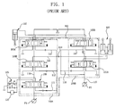
- the prior art hydraulic control device is provided with a first fluid pump P1 and a second fluid pump P2 each for generating a hydraulic flow to be used in the hydraulic control device.
- the hydraulic control device is further provided with a control valve 100 for controlling the hydraulic flows of the first and second fluid pumps P1, P2 supplied to the boom cylinder 105 and the arm cylinder 107.
- the control valve 100 includes a first control spool group 100A consisting of a boom second-speed control spool 101B and an arm first-speed control spool 103A, and a second control spool group 100B consisting of a boom first-speed control spool 101 A and an arm second-speed control spool 103B.
- Also included in the first spool group 100A is a swing control spool 109 for controlling actuation of a swing motor 120.
- the swing control spool 109, the boom second-speed control spool 101B and the arm first-speed control spool 103A are respectively provided on a first bypass line 110 from upstream to downstream in the named sequence for receiving the hydraulic flow from the first pump P1 via parallel lines 111, 112, 113.
- the boom first-speed control spool 101A and the arm second-speed control spool 103B are respectively provided on a second bypass line 115 from upstream to downstream in the named sequence for receiving the hydraulic flow from the second pump P2 via the parallel lines 116, 117.
- the hydraulic flow of the first fluid pump P1 is distributed to the swing control spool 109 and the boom second-speed control spool 101B to thereby actuate the swing motor 120 and the boom cylinder 105 at the second speed.
- the boom second-speed control spool 101B and the boom first-speed control spool 101A are connected to the boom cylinder 105 via a confluence line 112 so that the hydraulic flow of the first fluid pump P1 and the hydraulic flow of the second fluid pump P2 can be merged together in the confluence line 112 after passing through the boom second-speed control spool 101B and the boom first-speed control spool 101A, respectively.
- a check valve 123 is disposed on the confluence line 112 in such a manner that the check valve 123 allows the hydraulic flows passed the boom second-speed control spool 101B to be supplied to the boom cylinder 105 through the confluence line 112 but prevents the hydraulic flow passed the boom first-speed control spool 101A from flowing toward the boom second-speed control spool 101B.
- the swing actuation pressure is greater than the boom actuation pressure at an initial stage of the boom-swing frame combined motion during which the boom cylinder 105 and the swing motor 120 are actuated simultaneously.
- This causes the hydraulic flow of the first fluid pump P1 to be first supplied to the boom cylinder 105, thus balancing the actuation pressure of the boom cylinder 105 with that of the swing motor 120.
- the swing motor 120 is associated with a relief valve 125 that serves to limit the pressure of the hydraulic flow supplied to the swing motor to below a predetermined value.
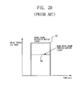
- the swing actuation pressure is increased up to a relief pressure of the relief valve 125 as illustrated by a line A1 in FIG. 2a and therefore the swing torque is also maximized as illustrated by a line A2 in FIG. 2b, thus enabling the swing operation to take place in a smooth manner.
- a hydraulic control device for controlling a boom-swing frame combined motion in an excavator that can increase a swing pressure up to a predetermined swing relief pressure to thereby facilitate the movement of a swing frame, in case of conducting composite operations such as a loading-on-truck operation, a ground leveling operation and the like on a sloping ground.
- the present invention provides a hydraulic control device for controlling a boom-swing frame combined motion in an excavator, comprising first and second fluid pumps, a swing control spool and a boom second-speed control spool respectively provided on parallel lines for receiving a hydraulic flow from the first pump via the parallel lines, a boom first-speed control spool for receiving a hydraulic flow from the second pump, a swing motor actuated by the hydraulic flow supplied from the first pump through the swing control spool, a boom cylinder actuated by the hydraulic flows supplied from the first and second pumps through the boom second-speed control spool and the boom first-speed control spool, a pilot control valve for providing a pilot pressure to displace the swing control spool, the boom first-speed control spool and the boom second-speed control spool, and a confluence line for merging the hydraulic flow from the boom second-speed control spool with that from the boom first-speed control spool, characterized by further comprising: a swing priority valve provided on
- variable orifice of the swing priority valve comprise a variable throttling section for reducing the aperture area in proportion to the magnitude of a swing control pilot pressure in the swing priority control line and a bleed-off section formed contiguous to the variable throttling section for keeping the aperture area constant.
- the hydraulic control device further comprise a selection switch and a selection valve provided on the swing priority control line for selectively opening and shutting off the swing priority control line in response to activation and deactivation of the selection switch.
- the operator can activate or turn on a selection switch to increase the swing actuation pressure or swing torque to a maximum value particularly at an initial of the boom-swing frame combined motion, thus facilitating the loading-on-truck operation on the sloping ground.
- the selection switch is deactivated or turned off so that the boom motion and the swing frame motion can be controlled depending on the actuation pressures applied to a boom cylinder and a swing motor without resort to the swing priority control noted above.
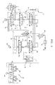
- FIG. 3 is a schematic diagram showing one embodiment of a hydraulic control device of the present invention.
- the hydraulic control device of the present invention is provided with a first fluid pump P1 and a second fluid pump P2 each for generating a hydraulic flow to be used in the hydraulic control device.
- the hydraulic flows discharged from the first and second fluid pumps P1, P2 are direction-controlled by a control valve 10 and then distributed to a variety of hydraulic actuators, such as a swing motor 1, a boom cylinder 3 and an arm cylinder 5, to actuate them in a controlled manner.
- a swing relief valve 2 is disposed on a fluid pressure line that interconnects the swing motor 1 and the first fluid pump P1.
- the control valve 10 includes a swing control spool 13 for controlling actuation of the swing motor 1, a boom first-speed control spool 11A for actuating the boom cylinder 3 at a relatively low speed (“first speed”), a boom second-speed, control spool 11B for actuating the boom cylinder 3 at a relatively high speed (“second speed”), an arm first-speed control spool 12A for actuating the arm cylinder 5 at a first speed, and an arm second-speed control spool 12B for actuating the arm cylinder 5 at a second speed.
- first speed a boom first-speed control spool 11A for actuating the boom cylinder 3 at a relatively low speed
- second-speed, control spool 11B for actuating the boom cylinder 3 at a relatively high speed
- an arm first-speed control spool 12A for actuating the arm cylinder 5 at a first speed
- an arm second-speed control spool 12B for actuating the arm cylinder 5 at a second speed.
- the swing control spool 13, the boom second-speed control spool 11B and the arm first-speed control spool 12A are disposed on a first bypass line 15 from upstream to downstream in the named sequence and connected to the first fluid pump P1 through parallel lines 16, 17, 18. Normally, the hydraulic flow of the first fluid pump P1 is drained to a tank via the first bypass line 15.
- the boom first-speed control spool 11A and the arm second-speed control spool 12B are disposed on a second bypass line 19 from upstream to downstream in the named sequence and connected to the second fluid pump P2 through parallel lines 20, 21. Normally, the hydraulic flow of the second fluid pump P2 is drained to a tank via the second bypass line 19.
- Outlet ports of the boom second-speed control spool 11B and the boom first-speed control spool 11A are connected in common to a confluence line 25 and kept in fluid communication with the boom cylinder 3 through the confluence line 25.
- a pilot control valve 24 is provided to, under the control of a manipulation lever 24a, reduce the pressure of a hydraulic flow discharged by a pilot pump P3 and then provide pilot pressure signals to each of the control spools 11A, 11B, 12A, 12B, 13.
- the boom first-speed control spool 11A and the boom second-speed control spool 11B are shifted to the left when viewed in FIG. 3. This assures that the hydraulic flow of the first fluid pump P1 and the hydraulic flow of the second fluid pump P2 pass respectively through the boom second-speed control spool 11B and boom first-speed control spool 11A and are merged together in the confluence line 25, after which the hydraulic flows thus merged are supplied to the boom cylinder 3 so as to actuate it at the second speed.
- a swing priority valve 30 is provided on the confluence line 25 for variably reducing the hydraulic flow supplied to the boom cylinder 3 through the confluence line 25 in proportion to the magnitude of a swing control pilot pressure provided from the pilot control valve 24.
- the swing priority valve 30 has a pressure receiving part 30a, a variable orifice 31 and a check valve 32.
- the pressure receiving part 30a of the swing priority valve 30 is connected to the pilot control valve 24 via a swing priority control line 27 and a swing control signal line 26 so that it can receive a swing control signal pressure from the pilot control valve 24.
- variable orifice 31 of the swing priority valve 30 has a variable throttling section (X) for reducing its aperture area in proportion to the magnitude of a swing control pilot pressure in the swing priority control line 27 and a bleed-off section (Y) formed contiguous to the variable throttling section (X) for keeping its aperture area constant.
- the swing control signal pressure acts on the swing control spool 13 of the control valve 10 and, at the same time, on the pressure receiving part 30a of the swing priority valve 30 through the swing priority control line 27.
- the swing priority valve 30 is normally biased upwards by a spring in such a manner that a specific part of the variable throttling section (X) is in alignment with the swing priority control signal line 27. If the swing priority control signal pressure is delivered to the pressure receiving part 30a through the swing priority control signal line 27, the swing priority valve 30 is displaced against the biasing force of the spring in such a manner that the bleed-off section (Y) comes into alignment with the swing priority control signal line 27.
- the spring for resiliently biasing the swing priority valve 30 in this manner has a spring constant as shown in FIG 3. As can be seen in FIG.
- variable throttling section (X) the aperture area of the swing priority valve 30 is sharply reduced at an initial stage and then gently decreased as the stroke of the swing priority valve 30 becomes greater.
- the bleed-off section (Y) the aperture area of the swing priority valve 30 is minimized and then kept constant regardless of the stroke of the swing priority valve 30.
- a selection valve 29 is provided on the swing priority control line 27 for selectively opening and shutting off the swing priority control line 27 in response to activation and deactivation of a selection switch 28 electrically associated with the selection valve 29.
- the selection valve 29 comes to open the swing priority control line 27 thus making the swing priority control available.
- the selection switch 28 is deactivated to cause the boom-swing frame combined motion, the selection valve 29 will shut off the swing priority control line 27 thus rendering the swing priority control function dead. This allows the boom cylinder 3 and the swing motor 1 to be actuated by the normally applied actuation pressures.
- the selection switch 28 is turned on to thereby open the swing priority control line 27. Then, the swing manipulation lever 24A and the boom manipulation lever 24B of the pilot control valve 24 are manipulated at one time to have the pilot control valve 24 generate a swing control signal pressure and a boom control signal pressure.
- the swing control signal pressure thus generated shifts the swing control valve 13 to the left or right so that the swing motor 1 can be rotated in a forward or reverse direction by the action of the hydraulic flow supplied from the first fluid pump P1.
- the swing control signal pressure is delivered to the pressure receiving part 30a of the swing priority valve 30 through the swing priority control line 27 to thereby shift the swing priority valve 30 downwards when viewed in FIG. 3.
- This enables the variable orifice 31 of the swing priority valve 30 to reduce the hydraulic flow of the first fluid pump P1 to be merged in the confluence line 25 with the hydraulic flow of the second fluid pump P2.
- the swing priority valve is adapted to automatically increase or decrease the moving speed of the swing frame in proportion to the magnitude of the swing control signal pressure generated by the pilot control valve, i.e., the degree of manipulation of the pilot control valve.
Landscapes
- Engineering & Computer Science (AREA)
- General Engineering & Computer Science (AREA)
- Mining & Mineral Resources (AREA)
- Civil Engineering (AREA)
- Structural Engineering (AREA)
- Physics & Mathematics (AREA)
- Fluid Mechanics (AREA)
- Mechanical Engineering (AREA)
- Operation Control Of Excavators (AREA)
- Fluid-Pressure Circuits (AREA)
Applications Claiming Priority (1)
| Application Number | Priority Date | Filing Date | Title |
|---|---|---|---|
| KR1020040110414A KR101155717B1 (ko) | 2004-12-22 | 2004-12-22 | 굴삭기의 붐-선회 복합동작 유압제어장치 |
Publications (3)
| Publication Number | Publication Date |
|---|---|
| EP1674735A2 true EP1674735A2 (de) | 2006-06-28 |
| EP1674735A3 EP1674735A3 (de) | 2009-07-15 |
| EP1674735B1 EP1674735B1 (de) | 2011-08-24 |
Family
ID=35851957
Family Applications (1)
| Application Number | Title | Priority Date | Filing Date |
|---|---|---|---|
| EP05027935A Ceased EP1674735B1 (de) | 2004-12-22 | 2005-12-20 | Hydraulische Steuerung für einen Auslegerschwenkantrieb mit kombinierten Bewegungen an einem Bagger |
Country Status (4)
| Country | Link |
|---|---|
| US (1) | US7275369B2 (de) |
| EP (1) | EP1674735B1 (de) |
| KR (1) | KR101155717B1 (de) |
| CN (1) | CN1793531B (de) |
Cited By (3)
| Publication number | Priority date | Publication date | Assignee | Title |
|---|---|---|---|---|
| EP1980674A1 (de) * | 2007-04-10 | 2008-10-15 | Kobelco Construction Machinery Co., Ltd. | Hydraulische Steuervorrichtung für eine Bearbeitungsmaschine |
| EP3290595A4 (de) * | 2015-04-29 | 2018-12-12 | Volvo Construction Equipment AB | Durchflussregler einer baumaschine und steuerungsverfahren dafür |
| EP3546663A1 (de) * | 2018-03-29 | 2019-10-02 | Kobelco Construction Machinery Co., Ltd. | Schwenkbare arbeitsmaschine |
Families Citing this family (24)
| Publication number | Priority date | Publication date | Assignee | Title |
|---|---|---|---|---|
| US7549241B2 (en) * | 2005-07-07 | 2009-06-23 | Nabtesco Corporation | Hydraulic control device for loader |
| US20090090102A1 (en) * | 2006-05-03 | 2009-04-09 | Wilfred Busse | Method of reducing the load of one or more engines in a large hydraulic excavator |
| CN101070707B (zh) * | 2007-05-29 | 2011-06-15 | 三一重机有限公司 | 一种挖掘机回转控制方法和系统 |
| US20110056192A1 (en) * | 2009-09-10 | 2011-03-10 | Robert Weber | Technique for controlling pumps in a hydraulic system |
| US20110056194A1 (en) * | 2009-09-10 | 2011-03-10 | Bucyrus International, Inc. | Hydraulic system for heavy equipment |
| US8718845B2 (en) | 2010-10-06 | 2014-05-06 | Caterpillar Global Mining Llc | Energy management system for heavy equipment |
| US8626403B2 (en) | 2010-10-06 | 2014-01-07 | Caterpillar Global Mining Llc | Energy management and storage system |
| US8606451B2 (en) | 2010-10-06 | 2013-12-10 | Caterpillar Global Mining Llc | Energy system for heavy equipment |
| US9190852B2 (en) | 2012-09-21 | 2015-11-17 | Caterpillar Global Mining Llc | Systems and methods for stabilizing power rate of change within generator based applications |
| JP5961579B2 (ja) * | 2013-04-01 | 2016-08-02 | 日立建機株式会社 | 油圧ショベル |
| JP6220227B2 (ja) * | 2013-10-31 | 2017-10-25 | 川崎重工業株式会社 | 油圧ショベル駆動システム |
| CN106164803B (zh) * | 2014-03-31 | 2019-04-05 | 沃尔沃建造设备有限公司 | 用于工程机械的作业装置的合流流量的控制装置及其控制方法 |
| JP6212009B2 (ja) * | 2014-09-12 | 2017-10-11 | 日立建機株式会社 | 作業機械の油圧制御装置 |
| CN104564868B (zh) * | 2014-11-24 | 2017-03-01 | 徐州重型机械有限公司 | 合流控制系统、方法及起重机 |
| WO2016098926A1 (ko) * | 2014-12-17 | 2016-06-23 | 볼보 컨스트럭션 이큅먼트 에이비 | 건설기계의 유압액츄에이터 구동 제어방법 |
| CN107429716B (zh) * | 2015-01-08 | 2019-05-14 | 沃尔沃建筑设备公司 | 建筑机械的液压致动器的驱动控制方法 |
| CN105041746B (zh) * | 2015-07-16 | 2017-05-31 | 河北工程大学 | 万向轴法兰叉头端面齿加工辅助设备液压控制装置 |
| CN106351909B (zh) * | 2016-08-30 | 2018-08-21 | 徐州重型机械有限公司 | 一种多供油单元合流切换系统 |
| EP3540128B1 (de) * | 2016-11-02 | 2022-03-09 | Volvo Construction Equipment AB | Hydrauliksteuerungssystem für baumaschine |
| CN107503997B (zh) * | 2017-09-15 | 2019-05-03 | 太原理工大学 | 背压与动力匹配液压混合动力调控双执行器系统 |
| EP3707389B1 (de) * | 2017-11-08 | 2024-04-24 | Volvo Construction Equipment AB | Hydraulikkreislauf |
| JP7131138B2 (ja) * | 2018-07-04 | 2022-09-06 | コベルコ建機株式会社 | 作業機械の油圧駆動装置 |
| JP7331786B2 (ja) * | 2020-06-09 | 2023-08-23 | コベルコ建機株式会社 | 旋回式建設機械 |
| CN117364876A (zh) * | 2023-11-03 | 2024-01-09 | 华侨大学 | 一种多泵合流电液系统及挖掘机 |
Family Cites Families (8)
| Publication number | Priority date | Publication date | Assignee | Title |
|---|---|---|---|---|
| JPH06240709A (ja) * | 1993-02-17 | 1994-08-30 | Yutani Heavy Ind Ltd | 油圧ショベルの油圧回路 |
| JP2892939B2 (ja) * | 1994-06-28 | 1999-05-17 | 日立建機株式会社 | 油圧掘削機の油圧回路装置 |
| KR0138161Y1 (ko) * | 1994-08-30 | 1999-04-15 | 토니헬샴 | 작업조건에 따라 액츄에이터의 속도 조정이 가능한 유압회로 |
| KR970011608B1 (ko) * | 1994-09-06 | 1997-07-12 | 대우중공업 주식회사 | 건설기계의 선회토르크 제어장치(an apparatus for controlling turning torque in a construction equipment) |
| JP3013225B2 (ja) * | 1995-01-11 | 2000-02-28 | 新キャタピラー三菱株式会社 | 吊り作業制御装置 |
| JP3550260B2 (ja) * | 1996-09-30 | 2004-08-04 | コベルコ建機株式会社 | アクチュエータ作動特性制御装置 |
| JP3419661B2 (ja) * | 1997-10-02 | 2003-06-23 | 日立建機株式会社 | 油圧建設機械の原動機のオートアクセル装置及び原動機と油圧ポンプの制御装置 |
| KR200180964Y1 (ko) * | 1998-04-17 | 2000-05-15 | 김형벽 | 굴삭기의 흙다지기 작업 제어장치 |
-
2004
- 2004-12-22 KR KR1020040110414A patent/KR101155717B1/ko not_active Expired - Fee Related
-
2005
- 2005-12-20 EP EP05027935A patent/EP1674735B1/de not_active Ceased
- 2005-12-21 US US11/315,420 patent/US7275369B2/en not_active Expired - Fee Related
- 2005-12-22 CN CN2005101322446A patent/CN1793531B/zh not_active Expired - Fee Related
Non-Patent Citations (1)
| Title |
|---|
| None |
Cited By (6)
| Publication number | Priority date | Publication date | Assignee | Title |
|---|---|---|---|---|
| EP1980674A1 (de) * | 2007-04-10 | 2008-10-15 | Kobelco Construction Machinery Co., Ltd. | Hydraulische Steuervorrichtung für eine Bearbeitungsmaschine |
| US7921764B2 (en) | 2007-04-10 | 2011-04-12 | Kobelco Construction Machinery Co., Ltd. | Hydraulic control device of working machine |
| EP3290595A4 (de) * | 2015-04-29 | 2018-12-12 | Volvo Construction Equipment AB | Durchflussregler einer baumaschine und steuerungsverfahren dafür |
| US10428491B2 (en) | 2015-04-29 | 2019-10-01 | Volvo Construction Equipment Ab | Flow rate control apparatus of construction equipment and control method therefor |
| EP3546663A1 (de) * | 2018-03-29 | 2019-10-02 | Kobelco Construction Machinery Co., Ltd. | Schwenkbare arbeitsmaschine |
| US11078645B2 (en) | 2018-03-29 | 2021-08-03 | Kobelco Construction Machinery Co., Ltd. | Slewing-type working machine |
Also Published As
| Publication number | Publication date |
|---|---|
| KR101155717B1 (ko) | 2012-06-12 |
| EP1674735A3 (de) | 2009-07-15 |
| EP1674735B1 (de) | 2011-08-24 |
| US7275369B2 (en) | 2007-10-02 |
| US20060130473A1 (en) | 2006-06-22 |
| CN1793531A (zh) | 2006-06-28 |
| KR20060071920A (ko) | 2006-06-27 |
| CN1793531B (zh) | 2010-04-21 |
Similar Documents
| Publication | Publication Date | Title |
|---|---|---|
| EP1674735B1 (de) | Hydraulische Steuerung für einen Auslegerschwenkantrieb mit kombinierten Bewegungen an einem Bagger | |
| EP1672128B1 (de) | Hydraulische Steuereinrichtung für Bagger mit verbesserter Ladeleistung an Steigungen | |
| JPH09268604A (ja) | 重装備用の流量合流装置 | |
| US7207175B2 (en) | Hydraulic control device for controlling a boom-arm combined operation in an excavator | |
| US4986072A (en) | Hydraulic actuator circuit with flow-joining control | |
| US7430859B2 (en) | Fluid pump control system for excavators | |
| RU2700971C2 (ru) | Гидравлическая система, способ управления и машина, содержащая данную гидравлическую систему | |
| WO2021039284A1 (ja) | 建設機械の油圧システム | |
| EP1764515A2 (de) | Hydrauliksystem für Baumaschinen | |
| US6581506B1 (en) | Method and device for controlling supply of working fluid | |
| JPH10159805A (ja) | 建設機械の作業装置用シリンダのための油圧装置 | |
| JP6071821B2 (ja) | 液圧駆動装置 | |
| JP2002005109A (ja) | 操作制御装置 | |
| JP3081968B2 (ja) | ロードセンシングシステムにおけるカットオフキャンセル機構 | |
| US10208457B2 (en) | Working machine control system | |
| US5615991A (en) | Variable priority device for heavy construction equipment | |
| JPH068641B2 (ja) | 油圧回路 | |
| JP7152968B2 (ja) | 油圧ショベル駆動システム | |
| JPH10310365A (ja) | クレーン兼用油圧ショベルの油圧制御回路 | |
| JP3724015B2 (ja) | パイロット切換弁の応答性可変装置 | |
| JPH0579060A (ja) | 油圧シヨベルの油圧回路 | |
| JP2001208005A (ja) | 油圧パイロット駆動式操作回路 | |
| JPH0893001A (ja) | 油圧パイロット操作回路 | |
| JP2685870B2 (ja) | 作業機械の油圧回路 | |
| KR100805058B1 (ko) | 굴삭기의 도랑파기작업용 유압제어장치 |
Legal Events
| Date | Code | Title | Description |
|---|---|---|---|
| PUAI | Public reference made under article 153(3) epc to a published international application that has entered the european phase |
Free format text: ORIGINAL CODE: 0009012 |
|
| AK | Designated contracting states |
Kind code of ref document: A2 Designated state(s): AT BE BG CH CY CZ DE DK EE ES FI FR GB GR HU IE IS IT LI LT LU LV MC NL PL PT RO SE SI SK TR |
|
| AX | Request for extension of the european patent |
Extension state: AL BA HR MK YU |
|
| 17P | Request for examination filed |
Effective date: 20080708 |
|
| PUAL | Search report despatched |
Free format text: ORIGINAL CODE: 0009013 |
|
| AK | Designated contracting states |
Kind code of ref document: A3 Designated state(s): AT BE BG CH CY CZ DE DK EE ES FI FR GB GR HU IE IS IT LI LT LU LV MC NL PL PT RO SE SI SK TR |
|
| AX | Request for extension of the european patent |
Extension state: AL BA HR MK YU |
|
| AKX | Designation fees paid |
Designated state(s): DE FR IT |
|
| GRAP | Despatch of communication of intention to grant a patent |
Free format text: ORIGINAL CODE: EPIDOSNIGR1 |
|
| GRAS | Grant fee paid |
Free format text: ORIGINAL CODE: EPIDOSNIGR3 |
|
| GRAA | (expected) grant |
Free format text: ORIGINAL CODE: 0009210 |
|
| AK | Designated contracting states |
Kind code of ref document: B1 Designated state(s): DE FR IT |
|
| REG | Reference to a national code |
Ref country code: DE Ref legal event code: R096 Ref document number: 602005029668 Country of ref document: DE Effective date: 20111110 |
|
| PLBE | No opposition filed within time limit |
Free format text: ORIGINAL CODE: 0009261 |
|
| STAA | Information on the status of an ep patent application or granted ep patent |
Free format text: STATUS: NO OPPOSITION FILED WITHIN TIME LIMIT |
|
| 26N | No opposition filed |
Effective date: 20120525 |
|
| REG | Reference to a national code |
Ref country code: DE Ref legal event code: R097 Ref document number: 602005029668 Country of ref document: DE Effective date: 20120525 |
|
| REG | Reference to a national code |
Ref country code: FR Ref legal event code: PLFP Year of fee payment: 11 |
|
| REG | Reference to a national code |
Ref country code: FR Ref legal event code: PLFP Year of fee payment: 12 |
|
| REG | Reference to a national code |
Ref country code: FR Ref legal event code: PLFP Year of fee payment: 13 |
|
| PGFP | Annual fee paid to national office [announced via postgrant information from national office to epo] |
Ref country code: DE Payment date: 20181204 Year of fee payment: 14 |
|
| PGFP | Annual fee paid to national office [announced via postgrant information from national office to epo] |
Ref country code: FR Payment date: 20181120 Year of fee payment: 14 |
|
| PGFP | Annual fee paid to national office [announced via postgrant information from national office to epo] |
Ref country code: IT Payment date: 20181220 Year of fee payment: 14 |
|
| REG | Reference to a national code |
Ref country code: DE Ref legal event code: R119 Ref document number: 602005029668 Country of ref document: DE |
|
| PG25 | Lapsed in a contracting state [announced via postgrant information from national office to epo] |
Ref country code: FR Free format text: LAPSE BECAUSE OF NON-PAYMENT OF DUE FEES Effective date: 20191231 Ref country code: DE Free format text: LAPSE BECAUSE OF NON-PAYMENT OF DUE FEES Effective date: 20200701 Ref country code: IT Free format text: LAPSE BECAUSE OF NON-PAYMENT OF DUE FEES Effective date: 20191220 |