EP1675751B1 - Motorisierte lampeneinstellvorrichtung - Google Patents
Motorisierte lampeneinstellvorrichtung Download PDFInfo
- Publication number
- EP1675751B1 EP1675751B1 EP04795821A EP04795821A EP1675751B1 EP 1675751 B1 EP1675751 B1 EP 1675751B1 EP 04795821 A EP04795821 A EP 04795821A EP 04795821 A EP04795821 A EP 04795821A EP 1675751 B1 EP1675751 B1 EP 1675751B1
- Authority
- EP
- European Patent Office
- Prior art keywords
- output shaft
- adjuster
- lamp
- housing
- motor
- Prior art date
- Legal status (The legal status is an assumption and is not a legal conclusion. Google has not performed a legal analysis and makes no representation as to the accuracy of the status listed.)
- Expired - Lifetime
Links
- 230000007246 mechanism Effects 0.000 claims description 4
- 230000000694 effects Effects 0.000 description 6
- 239000000463 material Substances 0.000 description 5
- 238000000034 method Methods 0.000 description 5
- 238000005286 illumination Methods 0.000 description 3
- 238000004519 manufacturing process Methods 0.000 description 3
- 239000004033 plastic Substances 0.000 description 3
- 238000012423 maintenance Methods 0.000 description 2
- 230000004044 response Effects 0.000 description 2
- 239000000725 suspension Substances 0.000 description 2
- 230000000712 assembly Effects 0.000 description 1
- 238000000429 assembly Methods 0.000 description 1
- 230000005540 biological transmission Effects 0.000 description 1
- 239000003638 chemical reducing agent Substances 0.000 description 1
- 230000007812 deficiency Effects 0.000 description 1
- 230000001815 facial effect Effects 0.000 description 1
- 239000002783 friction material Substances 0.000 description 1
- 238000002347 injection Methods 0.000 description 1
- 239000007924 injection Substances 0.000 description 1
- 230000003993 interaction Effects 0.000 description 1
- 230000007257 malfunction Effects 0.000 description 1
- 239000000203 mixture Substances 0.000 description 1
- 238000012986 modification Methods 0.000 description 1
- 230000004048 modification Effects 0.000 description 1
- 239000002991 molded plastic Substances 0.000 description 1
- 230000008439 repair process Effects 0.000 description 1
- 229910001220 stainless steel Inorganic materials 0.000 description 1
- 239000010935 stainless steel Substances 0.000 description 1
Images







Classifications
-
- B—PERFORMING OPERATIONS; TRANSPORTING
- B60—VEHICLES IN GENERAL
- B60Q—ARRANGEMENT OF SIGNALLING OR LIGHTING DEVICES, THE MOUNTING OR SUPPORTING THEREOF OR CIRCUITS THEREFOR, FOR VEHICLES IN GENERAL
- B60Q1/00—Arrangement of optical signalling or lighting devices, the mounting or supporting thereof or circuits therefor
- B60Q1/02—Arrangement of optical signalling or lighting devices, the mounting or supporting thereof or circuits therefor the devices being primarily intended to illuminate the way ahead or to illuminate other areas of way or environments
- B60Q1/04—Arrangement of optical signalling or lighting devices, the mounting or supporting thereof or circuits therefor the devices being primarily intended to illuminate the way ahead or to illuminate other areas of way or environments the devices being headlights
- B60Q1/06—Arrangement of optical signalling or lighting devices, the mounting or supporting thereof or circuits therefor the devices being primarily intended to illuminate the way ahead or to illuminate other areas of way or environments the devices being headlights adjustable, e.g. remotely-controlled from inside vehicle
- B60Q1/068—Arrangement of optical signalling or lighting devices, the mounting or supporting thereof or circuits therefor the devices being primarily intended to illuminate the way ahead or to illuminate other areas of way or environments the devices being headlights adjustable, e.g. remotely-controlled from inside vehicle by mechanical means
-
- B—PERFORMING OPERATIONS; TRANSPORTING
- B60—VEHICLES IN GENERAL
- B60Q—ARRANGEMENT OF SIGNALLING OR LIGHTING DEVICES, THE MOUNTING OR SUPPORTING THEREOF OR CIRCUITS THEREFOR, FOR VEHICLES IN GENERAL
- B60Q1/00—Arrangement of optical signalling or lighting devices, the mounting or supporting thereof or circuits therefor
- B60Q1/02—Arrangement of optical signalling or lighting devices, the mounting or supporting thereof or circuits therefor the devices being primarily intended to illuminate the way ahead or to illuminate other areas of way or environments
- B60Q1/04—Arrangement of optical signalling or lighting devices, the mounting or supporting thereof or circuits therefor the devices being primarily intended to illuminate the way ahead or to illuminate other areas of way or environments the devices being headlights
- B60Q1/06—Arrangement of optical signalling or lighting devices, the mounting or supporting thereof or circuits therefor the devices being primarily intended to illuminate the way ahead or to illuminate other areas of way or environments the devices being headlights adjustable, e.g. remotely-controlled from inside vehicle
- B60Q1/076—Arrangement of optical signalling or lighting devices, the mounting or supporting thereof or circuits therefor the devices being primarily intended to illuminate the way ahead or to illuminate other areas of way or environments the devices being headlights adjustable, e.g. remotely-controlled from inside vehicle by electrical means including means to transmit the movements, e.g. shafts or joints
Definitions
- the present invention relates generally to adjusters which are used to adjust the aim of a vehicle lamp. Specifically, this invention relates to a motorized lamp adjuster for adjusting the aim of a vehicle lamp using motorized or manual operation.
- Vehicles such as automobiles typically have several lamps including head lamps and fog lamps. These lamps typically include a reflector sealed to a lens with a bulb therein. These lamps are securely fit into mounting brackets. The lamps are usually pivotally engaged to the mounting bracket at a plurality of points. The mounting brackets are attached to the vehicle. Together, a lamp and a mounting bracket form a complete lamp assembly. Once the lamp assembly has been manufactured and installed into a vehicle, the aim of the lamp must be adjusted to the proper aim. As a result of accidents, maintenance, and normal vibrations and wear, the aim of the lamp must be occasionally adjusted during the lifetime of the vehicle.
- One method of adjusting the aim of the lamp involves using an adjuster.
- the adjuster may be formed as part of the mounting bracket or may be a separate part that communicates with both the lamp and the mounting bracket.
- One known type of adjuster comprises a housing and an output shaft extending there from. The output shaft is engaged to the lamp. - Actuation or operation of the adjuster causes the output shaft to move with respect to the lamp assembly. Such movement causes the lamp to pivot with respect to the mounting bracket, thereby adjusting the aim of the lamp.
- the housing of the adjuster has an opening and a gear positioned inside the housing.
- the gear is functionally engaged to the output shaft.
- a driver is inserted into the opening and interacts with the gear. Actuation of the driver results in rotation of the gear and engaged output shaft.
- the gear translates actuation of the driver into movement of the output shaft.
- a manual adjuster has limited applicability. Many countries require a driver to be able to adjust the aim of a vehicle's lamps from inside the cabin. Additionally, certain vehicles are now offering lamps that track and illuminate the direction of the vehicle or that adjust the aim of the lamp to compensate for the pitch of the road or weight of the vehicle (i.e. driving on hilly terrain or with a heavy load in the vehicle). The aim of the lamp is automatically adjusted as the steering wheel is turned or as a result of the relative pitch of the suspension.
- a computer coordinates the degree of turn of the steering wheel, the speed of the vehicle, and/or the pitch of the suspension with the aim of the lamps. This coordination requires a high degree of precision. A driver cannot safely turn a steering wheel and manually adjust the aim of the vehicle's lamps at the same time.
- a number of motorized lamp adjusters have been developed to provide improved functionality. Many of these adjusters provide for both manual and motorized operation. In practice, the adjusters are manually operated to aim the lamp during manufacture, maintenance, and repair of the vehicle. The adjusters rely on motorized operation to aim the lamp while the vehicle is on the road. These adjusters can be connected to control units that provide for automatic adjustments while the vehicle is driven. Examples of such adjusters are disclosed in U.S. Patent No. 5,394,318 to Komachi ; U.S. Patent No. 5,673,991 to Eickhoff et al. ; and U.S. Patent No. 6,012,829 to Natchoo . These adjusters all use an electric motor to longitudinally move a output shaft.
- the motors are offset from the output shaft and located inside the adjuster housing.
- These adjusters rely on a series of gears, speed reducers, circuits, potentiometers, and transmissions to translate the power generated by the motor into longitudinal movement of the output shaft.
- these adjusters employ a series of parts. Each part must be separately manufactured. The parts are then assembled inside the housing to form the adjuster. Using multiple parts increases the potential for malfunction, breakage and general wearing of the adjuster. Further, using a series of parts results in a larger housing and thus a larger adjuster. Such an adjuster requires more space in a vehicle, thereby affecting the overall design and manufacture of the vehicle and making the overall cost of both the adjuster and the vehicle more expensive.
- US application No. 2002/0018348 describes an illumination axis adjusting apparatus that includes a stepping motor integrally having in turn an automotive angle adjusting structure for automatically adjusting the angle of the illumination axis of an automotive headlamp by driving the motor and a mutual angle adjusting structure for manually adjusting the angle of the illumination axis o the headlamp.
- US patent No. 5,673, 991 describes a manual and an electromotive actuatable adjusting apparatus for a reflector of a motor-vehicle heading are arranged together in a common housing.
- An adjusting pin, which is attached the reflector, can be moved along its length axis by both the manual and the electromotor adjusting apparatus.
- European application EP 0,291, 379 describes a device for controlling the orientation of a motor vehicle headlamp that comprises an adjusting device traversing an aperture of a casing.
- the adjusting device traverses the side face of the casing and interacts with an adjustment collar housed in the casing and engages in a rod.
- the present invention provides a motorized lamp adjuster that is cost-effective, provides improved functionality, and which solves certain of the problems raised or not solved by existing designs.
- the adjuster of the invention according to claim 1 includes a housing, a motor, and an output shaft.
- the output shaft passes through the housing and the motor and is functionally engaged by the motor such that operation of the motor causes axial movement of the output shaft.
- An anti-rotation gear is ideally positioned inside the housing such that the output shaft passes through and is functionally engaged by the anti-rotation gear.
- the anti-rotation gear is used to operate the adjuster manually.
- the anti-rotation gear also prevents the output shaft from rotating when the motor is in use.
- the anti-rotation gear is positioned in the housing such that the anti-rotation gear is biased against rotation.
- the output shaft preferably has a rotation point and the anti-rotation gear is configured to geometrically mate with the rotation point such that manual rotation of the anti-rotation gear causes the output shaft to rotate.
- the adjuster is operated manually by inserting a driver into the housing and rotating the driver.
- the driver can be inserted through a driver input locator in the housing. Once inserted, the driver functionally engages the output shaft through the anti-rotation gear such that rotation of the driver causes the output shaft to rotate and move axially.
- the driver may alternatively be included as part of the adjuster assembly.
- a drive gear is positioned within the housing such that the output shaft passes through the drive gear but does not engage the drive gear. Instead, the drive gear engages a ball insert that is functionally engaged to the output shaft. Motorized operation of the adjuster using the motor causes the output shaft to move axially, which in turn causes the ball insert to move axially and effectuate an adjustment to the aim of the lamp. To manually operate the adjuster, a driver engages the drive gear to rotate the drive gear, which rotates the ball insert and causes the ball insert to move axially with respect to the output shaft and effectuate an adjustment to the aim of the lamp. The output shaft does not rotate or move axially during manual operation.
- the functional engagement between the ball insert and the output shaft includes a clutching mechanism.
- the present invention may also include a lamp assembly.
- the lamp assembly has a mounting bracket, a lamp pivotally engaged within the mounting bracket, and an adjuster in accordance with any embodiment of the present invention.
- the adjuster is securely engaged to the mounting bracket and functionally engaged to the lamp.
- a power source and/or control unit is electrically connected to the motor if motorized adjustment is desired.
- FIGS. 1 through 13 Illustrative examples of a motorized lamp adjuster (identified generally as 30) are shown in FIGS. 1 through 13 . These examples do not form part of the present invention. While the invention may be susceptible to embodiment in different forms, there are shown in the drawings (i.e. Figures 14-31 ), and are described herein in detail, certain illustrative embodiments with the understanding that the present disclosure is to be considered an exemplification of the principles of the invention, and is not intended to limit the invention to those embodiments illustrated and described herein. Additionally, features illustrated and described with respect to one embodiment could be used in connection with other embodiments.
- the adjuster 30 is generally used in connection with a vehicle lamp and forms part of the lamp assembly 20.
- a lamp assembly 20 typically includes a lamp 21 and a mounting bracket 28.
- the lamp 21 has a reflector 24 sealed to or otherwise enclosed by a lens 22, and a bulb 26 disposed between the reflector 24 and the lens 22.
- the lamp 21 can be pivotally engaged to the mounting bracket 28.
- the mounting bracket 28 could form a portion of the lamp 21.
- the reflector 24 is mounted to the mounting bracket via a pivot post 100.
- the adjuster 30 securely engages the mounting bracket 28 and functionally 20 engages the lamp 21.
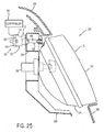
- the adjuster 30 may engage any portion of the lamp 21, such as the reflector 24 as shown in FIGS 25 and 26 .
- FIGS. 14-31 Common to all embodiments shown in FIGS. 14-31 is a housing 32 which engages the mounting bracket 28.
- the housing 32 can be constructed from any suitable rigid material and manufactured by any suitable technique. It has been found feasible to manufacture the housing from injection molded plastic.
- the housing 32 has a nose 64 and a body 66.
- the nose 64 engages the mounting bracket 28.
- the nose 64 may be securely engaged to the mounting bracket 28 via sliding engagement, snap fit, screw in, or other method. Examples of how an adjuster can be mounted to a bracket are shown in the following U.S. Patents to Burton 6,474,850; 6,257,747; 6,050,712; 6,042,254; and 5,707,133.
- the adjuster 30 may be mounted or securely engaged to the mounting bracket 28 via sliding engagement, snap fit, screw in, quarter-turn fashion, or other method.
- the housing 32 can be engaged to the mounting bracket 28 in a quarter-turn fashion.
- the mounting bracket 28 has an opening configured to mate with the nose 64.
- the nose 64 is inserted into the opening and turned, thereby securing the housing 32 to the mounting bracket 28.
- the nose 64 is ideally turned sixty degrees, however, turns of other degrees would also be possible.
- an O-ring or gasket 62 is positioned on the nose 64 and against the body 66.
- a motor 36 having a rotor 44 is also common to all embodiments shown in FIGS.14-31.
- the motor 36 is ideally electrically connected to a power supply via a control cord 91 to a connector 92.
- the power supply is preferably the battery of the vehicle.
- the motor 36 is electrically connected to a control unit 90 by control cord 91.
- the control unit 90 may be an electronic control unit (ECU), computer, electrical signal transmitter, or a switch.
- ECU electronice control unit
- Several types of motors could be used, including, but not limited to, a stepper motor such as the NMB Stepper Motor PL35L-02-USNJA, or a linear motor such as the MPL35A-24 linear motor manufactured by Taishan Siang.
- the drawings show the motor 36 and output shaft 38 as separate parts, it is of course also possible to purchase a pre-assembled motor unit in which the output shaft 38 has already been assembled into the motor 36.
- the adjuster 30 includes a number of parts.
- the adjuster 30 includes a housing 32 and a motor 36.
- the motor 36 is positioned in, or in contact with, the housing 32.
- a output shaft 38 is positioned in and extends through the housing 32 and the motor 36.
- the output shaft 38 interacts with and is functionally engaged at one end to the lamp 21, as shown in FIGS. 11 and 13 , and engaged to the motor 36 at the other end.
- An anti-rotation gear 40 is positioned inside the housing 32. The output shaft 38 is inserted into and through the anti-rotation gear 40.
- the body 66 has a receptor 68 which extends into the nose 64, a recess 70, and a driver input locator 72.
- An anti-rotation gear 40 is positioned inside the body 66 of the housing 32.
- the anti-rotation gear 40 has an extension 74 and a head 76 with a plurality of gear teeth 48 thereon.
- the gear teeth 48 are oriented toward the extension 74.
- the gear teeth 48 may be oriented away from the extension 74.
- the anti-rotation gear 40 is constructed from a single piece of plastic, but other configurations are possible.
- the extension 74 In positioning the anti-rotation gear 40 inside the body 66, the extension 74 is inserted into the receptor 68. As shown in FIGS. 5 and 6 , the extension 74 preferably snap fits into the receptor 68. Inserting the extension 74 into the receptor 68 causes the head 76 to abut the recess 70. As shown in FIG. 3 , the recess 70 has at least one flex point 56.
- the flex point 56 may take a variety of forms. For example, it has been found effective for the recess to have three flex points 56 as shown in FIG. 7 , but other numbers of flex points 56 may be used.
- the flex point 56 interacts with and functionally engages the anti-rotation gear 40. As shown in FIG.
- the flex point 56 interacts with the gear teeth 48.
- the flex point 56 allows the anti-rotation gear 40 to rotate when the adjuster 30 is manually operated via the driver 41, but prevents the anti-rotation gear 40 from rotating when the adjuster 30 is operated via the motor 36.
- the interference between the anti-rotation gear 40 and the housing 32, or other interferences within the device may be great enough to prevent rotation of the anti-rotation gear 40 when the adjuster 30 is operated via the motor 36. In such an arrangement the adjuster 30 does not have any flex points 56 positioned therein.
- the adjuster 30 is manually operated by actuating a driver 41 inserted into the driver input locator 72 (see, e.g., FIG. 2 ).
- the driver 41 can be locked in place by a driver retainer 94 positioned in the driver input locator 72.
- the driver 41 preferably has a groove 95 positioned thereon that snap fits into the driver retainer 94.
- the driver 41 functionally engages the gear teeth 48 of the anti-rotation gear 40.
- the gear teeth 48 are configured to functionally interact and geometrically mate with the driver 41, preferably with driver teeth 50 as shown. Actuating the driver 41 causes the anti-rotation gear 40 to rotate.
- the head 52 of the driver 41 can be engaged and turned by a tool such as a wrench, screwdriver, or TORX® driver.
- a tool such as a wrench, screwdriver, or TORX® driver.
- the driver 41 itself can be a tool such as a flat head, Phillips head, or a TORX® driver, depending on the configuration of the gear teeth 48.
- the output shaft 38 is inserted through the anti-rotation gear 40 and extends past the nose 64 of the housing 32.
- the output shaft 38 has a lamp end 78, at least one rotation point 46, and a driver end 82.
- the lamp end 78 of the output shaft 38 is engaged to the lamp 21, as shown in FIGS. 11 and 13 .
- the lamp end 78 is engaged to the reflector 24, but other points of attachment to the lamp 21 may be used.
- the lamp end 78 is ideally engaged to the lamp 21 via a ball 60.
- the ball 60 can be any material, but it has been found effective for the ball 60 to be constructed of a flexible material such as plastic.
- the output shaft 38 may be directly engaged to the lamp 21, engaged to a grommet engaged to the lamp 21, and/or may include a ball 60 formed as part of the output shaft 38 or any other form of pivoting mechanism.
- the output shaft 38 is inserted into, passes through, and is in contact with the anti-rotation gear 40.
- the output shaft 38 passes through a bearing 42 fit into the head 76 of the anti-rotation gear 40.
- the bearing 42 reduces the amount of wear on the anti-rotation gear 40 and the rotor 44 due to the interaction there between.
- the output shaft 38 passes through an additional bearing 96 positioned between the rotor 44 and the stator or drive unit 45.
- the bearings 42 and/or 96 are preferably manufactured from a low friction material such as stainless steel.
- the output shaft 38 has at least one anti-rotation point 46.
- the anti-rotation point 46 can take a variety of forms, shapes, and numbers depending on the exact configuration and desired characteristics of the adjuster 30.
- the extension 74 of the anti-rotation gear 40 is configured to geometrically mate with the output shaft 38 and the rotation point 46.
- the anti-rotation point 46 is a small bolt inserted through the output shaft 38 at an angle, preferably ninety degrees, relative to the axis of the output shaft 38.
- the extension 74 of the anti-rotation gear 40 has an interior 84 with a central round opening 85.
- the output shaft 38 inserts through the central round opening 85.
- the rotation point 46 functionally engages the anti-rotation gear 40.
- Rotation of the anti-rotation gear 40 causes the interior 84 of the extension 74 to come into contact with the rotation point 46.
- the interior 84 exerts a force on the rotation point 46, thus rotating the output shaft 38. Therefore as shown in FIG. 7 , the anti-rotation gear 40 and output shaft 38 rotate as a single unit.
- the driver end 82 of the output shaft 38 is inserted in and engaged to the motor 36.
- the motor 36 includes a rotor 44 and a drive unit 45.
- the drive unit 45 has a stator 93 and a connector 92.
- the rotor 44 is positioned inside the drive unit 45.
- the driver end 82 and the rotor 44 are threaded together.
- the driver end 82 is threaded into the rotor 44.
- the adjuster 30 can be operated either manually or via the motor 36.
- the adjuster 30 adjusts the aim of the lamp 21 via axial movement of the output shaft 38.
- the housing 32 of the adjuster 30 is engaged to the mounting bracket 28.
- the output shaft 38 of the adjuster 30 is engaged to the lamp 21, preferably via ball 60.
- operation of the adjuster 30 causes the output shaft 38 to move axially. Such movement results in pivoting of the lamp 21, thereby adjusting the aim of the lamp 21.
- Manual operation is accomplished by actuating the driver 41 positioned in the body 66 of the housing 32. Actuating the driver 41 results in rotation of the anti-rotation gear 40 and the output shaft 38.
- Rotation of the output shaft 38 causes the output shaft 38 to move along its axis, as it is threaded through the rotor 44 that is fixed during manual operation. Rotation of the output shaft 38 in one direction causes the output shaft 38 to extend towards the lamp 21. Rotation in the opposite direction causes the output shaft 38 to retract from the lamp 21. As such, rotation of the output shaft 38 results in axial movement of the output shaft 38.
- Motorized operation is accomplished by actuation of the motor 36 engaged to the driver end 82 of the output shaft 38. Actuation of the motor 36 causes the rotor 44 to rotate therein. As discussed, the driver end 82 and the rotor 44 are threaded together.
- the anti-rotation gear 40 prevents the output shaft 38 from rotating during motorized operation of the adjuster 30. Therefore, rotation of the threaded rotor 44 about the threaded portion of the output shaft 38 results in the output shaft 38 moving along its axis.
- FIGS. 14-31 A preferred embodiment of the adjuster 30 of the present invention is illustrated in FIGS. 14-31 .
- the adjuster 30 shown in FIGS. 14-31 includes a number of the same parts as the example of FIGS. 1-13 , and unless described otherwise herein, the common parts perform the same functions and can take the same form in each embodiment.
- the adjuster includes a housing 32, a motor 36, and an output shaft 38 inserted through the housing 32 and the motor 36.
- the housing 32 may be a two-part housing as shown, including a back housing portion 33 and a front housing portion 34. Other housing configurations are certainly possible, however, including a configuration such as the one-piece housing used in the example shown in FIGS.
- the front housing portion 34 includes a body 66, a nose 64, and a driver input locator 72.
- the motor 36 is positioned in, or in engagement with, the housing 32.
- the motor 36 includes a rotor 44, which is functionally engaged with the output shaft 38 using a threaded connection.
- the motor 36 also includes a front flange 43.
- An anti-rotation point 46 is located on the output shaft 38. The output shaft 38 is inserted into and through the motor 36 such that anti-rotation point 46 is disposed within a channel 47 within the motor flange 43.
- the disposition of the anti-rotation point 46 within the channel 47 allows the output shaft 38 to traverse axially over a distance equal to the length of the channel 47, but prevents the output shaft 38 from rotating.
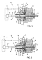
- the axial movement of the output shaft 38 is illustrated best in FIGS. 18 and 19 .
- the anti-rotation point 46 is located near the middle of channel 47, and, after axial movement of the output shaft 38 caused by motorized operation of the adjuster 30, the anti-rotation point 46 is shown near the front end of the channel 47 in FIG. 19 .
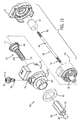
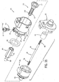
- the output shaft 38 is inserted into and through a drive gear 39 positioned at least partially inside the housing 32.
- the drive gear 39 is preferably constructed from a single piece of plastic, but other configurations and materials could be used.
- the output shaft 38 has a driver end 82 that engages the motor 36 and a lamp end 78 that engages the lamp 21 via ball insert 59.
- the drive gear 39 has an extension 75 and a head 77 having gear teeth 49 formed on one side thereof.
- FIGS. 15 and 16 show the gear teeth 49 formed on the extension side of the head 77 and thus oriented toward the extension 75, but the gear teeth 49 could be formed on the other side of the head 77 and oriented away from the extension 75.
- the ball insert 59 includes a ball 60 and an extension 61.
- the drive gear 39 functionally engages the ball insert 59.
- the drive gear extension 75 can include longitudinal splines 102 that engage the ball insert extension 61.
- FIGS. 14-26 show a drive gear extension 75 having external splines 102 that engage an internal hex geometry of the ball insert 61, as is best shown in FIG. 24 .
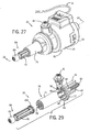
- FIGS. 27-31 show a drive gear extension 75 having internal splines 102 that engage clutching tabs 104 formed on the exterior of the ball insert extension 61. Other engagement methods could also be employed.
- a driver 41 having a head 52 and drive teeth 50 is inserted into the driver input locator 72 such that teeth 50 engage the gear teeth 49 of the drive gear 39, as can best be seen in FIGS. 18-21 and 28 .
- the driver 41 is used to manually operate the adjuster 30.
- Manual rotation of the driver 41 effects movement of the ball insert 59.
- Rotation of the driver 41 causes the drive gear 39 to rotate, which in turn causes the ball insert 59 to rotate.
- the ball insert 59 is engaged with the output shaft 38 using a threaded connection. As the ball insert 59 rotates, the ball insert 59 moves axially with respect to the output shaft 38, which is fixed during manual operation of the adjuster.
- the output shaft 38 in a fixed position during manual operation of the adjuster 30 allows the output shaft 38 to stay in its nominal position during manual operation of the adjuster.
- Rotating the drive gear 39 in one direction will effect forward axial movement of the ball insert 59, and rotating the drive gear 39 in the other direction will effect backward axial movement of the ball insert 59 as illustrated in FIG. 20 .
- at least one flex point 56 may be used to ensure that the drive gear 39 cannot rotate unless enough torque is applied to the driver 41 to overcome the resistance imposed on the gear teeth 49 by the flex point 56.
- the interference between the drive gear 39 and the housing 32 or other interferences within the device could also be great enough to prevent this unwanted rotation of the driver 41 and drive gear 39 without the use of any flex points 56.
- clutching tabs 104 can be used to prevent the application of excessive torque during manual operation. For example, if a vehicle technician is using the driver 41 to adjust the head lamp, and the ball insert 59 becomes restricted by something the technician cannot see, the technician may continue to apply torque to the driver 41 in an attempt to overcome the restriction. The clutching tabs 104 will, in response to this excessive torque, collapse inwardly and disengage the ball insert 59 from the drive gear 39, thereby clutching the system to prevent mechanical failures due to the excessive torque applied to the driver 41.
- axial movement of the output shaft 38 effects movement of the ball insert 59 as shown best in FIGS. 18 and 19 .
- the rotor 44 of the motor 36 rotates about the output shaft 38, which is engaged thereto using a threaded connection.
- Anti-rotation point 46 prevents the output shaft 38 from rotating, and thus the output shaft 38 moves along its axis as the rotor 44 rotates.
- Ball insert 59 is engaged to the output shaft 38, and can slide with respect to the drive gear extension 75.
- Rotation of the rotor 44 in one direction effects forward axial movement of the ball insert 59 as shown in FIG. 19
- rotation of the rotor 44 in the other direction effects backward axial movement of the ball insert 59.
- the motorized lamp adjuster 30 of the present invention may have other applications aside from use in connection with vehicle lamp assemblies.
Landscapes
- Engineering & Computer Science (AREA)
- Mechanical Engineering (AREA)
- Lighting Device Outwards From Vehicle And Optical Signal (AREA)
- Non-Portable Lighting Devices Or Systems Thereof (AREA)
- Securing Globes, Refractors, Reflectors Or The Like (AREA)
Claims (6)
- Lampeneinstellvorrichtung (30), die aufweist:ein Gehäuse (32);einen an dem Gehäuse angebrachten Motor (36);ein Antriebsrad (39), das zumindest teilweise von dem Gehäuse gelagert wird;eine Ausgangswelle (38), die zumindest teilweise durch ein erstes Ende (82) zu dem Motor (36) geht und mit diesem verbunden ist und die ein zweite Ende (78) hat, das für den Eingriff in einen Kugeleinsatz (59) geeignet ist, wobei der Kugeleinsatz (59) sowohl mit dem Antriebsrad (39) als auch dem zweiten Ende (78) der Ausgangswelle (38) in Eingriff ist;wobei die Betätigung des Motors (36) bewirkt, dass sowohl die Ausgangswelle (38) als auch der Kugeleinsatz (59) entlang der Achse der Ausgangswelle (38) verschoben werden; und
wobei die Drehung des Antriebsrads (39) bewirkt, dass der Kugeleinsatz (59) sich dreht und sich ohne Bewegung der Ausgangswelle (38) axial entlang der Achse der Ausgangswelle bewegt. - Lampeneinstellvorrichtung nach Anspruch 1, wobei das Gehäuse (32) eine Antriebseinsatzfixierung (72) umfasst, in welche ein Antrieb (41) eingesetzt werden kann, um das Antriebsrad (39) zu drehen.
- Lampeneinstellvorrichtung nach Anspruch 1, die ferner einen Kupplungsmechanismus (104) aufweist, der zwischen dem Kugeleinsatz (59) und dem Antriebsrad (39) angeordnet ist.
- Lampeneinstellvorrichtung nach Anspruch 3, wobei der Kupplungsmechanismus (104) Kupplungslappen (104) umfasst, die auf dem Kugeleinsatz (59) ausgebildet sind.
- Lampeneinstellvorrichtung nach Anspruch 1 wobei der Kugeleinsatz (59) Lappen umfasst, die mit dem Antriebsrad (59) eingreifen.
- Lampenanordnung (20), die aufweist:eine Lampeneinstellvorrichtung (30) nach einem der vorhergehenden Ansprüche;eine Halterung (28); undeine Lampe (21), die schwenkbar auf der Haltering (28) positioniert ist.
Applications Claiming Priority (2)
| Application Number | Priority Date | Filing Date | Title |
|---|---|---|---|
| US10/692,293 US7004607B2 (en) | 2003-10-23 | 2003-10-23 | Motorized lamp adjuster |
| PCT/US2004/034711 WO2005042304A2 (en) | 2003-10-23 | 2004-10-21 | Motorized lamp adjuster |
Publications (3)
| Publication Number | Publication Date |
|---|---|
| EP1675751A2 EP1675751A2 (de) | 2006-07-05 |
| EP1675751A4 EP1675751A4 (de) | 2008-07-02 |
| EP1675751B1 true EP1675751B1 (de) | 2010-12-15 |
Family
ID=34522087
Family Applications (1)
| Application Number | Title | Priority Date | Filing Date |
|---|---|---|---|
| EP04795821A Expired - Lifetime EP1675751B1 (de) | 2003-10-23 | 2004-10-21 | Motorisierte lampeneinstellvorrichtung |
Country Status (6)
| Country | Link |
|---|---|
| US (2) | US7004607B2 (de) |
| EP (1) | EP1675751B1 (de) |
| JP (1) | JP4592706B2 (de) |
| AT (1) | ATE491600T1 (de) |
| DE (1) | DE602004030598D1 (de) |
| WO (1) | WO2005042304A2 (de) |
Cited By (1)
| Publication number | Priority date | Publication date | Assignee | Title |
|---|---|---|---|---|
| EP2995500A1 (de) | 2014-09-12 | 2016-03-16 | Zizala Lichtsysteme GmbH | Einstellsystem für einen fahrzeugscheinwerfer |
Families Citing this family (36)
| Publication number | Priority date | Publication date | Assignee | Title |
|---|---|---|---|---|
| FR2865977B1 (fr) * | 2004-02-09 | 2006-06-02 | Sonceboz Sa | Dispositif de positionnement de phares |
| US7195384B2 (en) * | 2005-03-15 | 2007-03-27 | Tyc Brother Industrial Co., Ltd. | Adjusting device for head light system |
| DE602005009941D1 (de) * | 2005-06-30 | 2008-11-06 | Tyc Brother Ind Co Ltd | Einstellvorrichtung für ein Scheinwerfersystem |
| US7284887B2 (en) * | 2005-09-08 | 2007-10-23 | Asyst Technologies, Llc | Sliding adjuster |
| US7438457B2 (en) * | 2005-11-14 | 2008-10-21 | Asyst Technologies, Llc | Input shaft for a lamp adjuster |
| US7322726B2 (en) * | 2005-12-16 | 2008-01-29 | Magna International Inc. | One hundred and eighty degree headlamp adjuster |
| DE102006034243A1 (de) * | 2006-07-21 | 2008-01-31 | Schefenacker Vision Systems Germany Gmbh | Scheinwerferverstellvorrichtung mit Getriebe |
| JP4623049B2 (ja) * | 2007-04-25 | 2011-02-02 | 市光工業株式会社 | 車両用前照灯のレベリング装置 |
| US7824087B2 (en) * | 2007-05-23 | 2010-11-02 | Asyst Technologies, Llc | Headlamp adjuster |
| DE102008013017A1 (de) | 2007-08-28 | 2009-03-05 | Saia-Burgess Murten Ag | Stellantrieb |
| TWI351159B (en) * | 2007-12-26 | 2011-10-21 | Delta Electronics Inc | Motor and guiding structure thereof |
| US8033700B2 (en) * | 2008-05-02 | 2011-10-11 | Asyst Technologies L.L.C. | Travel limiting headlamp adjuster |
| JP5221210B2 (ja) * | 2008-05-30 | 2013-06-26 | アスモ株式会社 | ランプ装置、及び車両用ランプ装置 |
| TW201038878A (en) * | 2009-04-21 | 2010-11-01 | ProLight Opto Technology Cooperation | Adjustable condenser seat |
| KR101694541B1 (ko) * | 2010-04-02 | 2017-01-09 | 엘지이노텍 주식회사 | 리니어 스텝 모터 |
| JP5566799B2 (ja) * | 2010-07-08 | 2014-08-06 | 株式会社小糸製作所 | 車両用灯具 |
| DE102010061428A1 (de) * | 2010-12-21 | 2012-06-21 | Hella Kgaa Hueck & Co. | Einstellvorrichtung für Scheinwerfer |
| JP2011105310A (ja) * | 2011-03-04 | 2011-06-02 | Asmo Co Ltd | ランプ装置、及び車両用ランプ装置 |
| JP5700813B2 (ja) * | 2011-04-08 | 2015-04-15 | 株式会社小糸製作所 | 車輌用前照灯 |
| KR101939397B1 (ko) * | 2012-06-15 | 2019-01-16 | 엘지이노텍 주식회사 | 스크류 조인트를 가지는 전동기 |
| US9709235B2 (en) | 2012-07-20 | 2017-07-18 | Burton Technologies, Llc | Synchronized lamp adjuster |
| US9643529B2 (en) * | 2012-07-20 | 2017-05-09 | Burton Technologies, Llc | Synchronized lamp adjuster |
| JP6313958B2 (ja) * | 2013-11-19 | 2018-04-18 | タカハタプレシジョンジャパン株式会社 | 車両用灯具のレベリング装置 |
| AT515451B1 (de) * | 2014-03-10 | 2016-02-15 | Zizala Lichtsysteme Gmbh | Einstellvorrichtung für einen Fahrzeugscheinwerfer |
| KR102303222B1 (ko) * | 2014-11-11 | 2021-09-16 | 현대모비스 주식회사 | 자동차의 조명장치 |
| FR3031328B1 (fr) * | 2015-01-06 | 2018-06-01 | Aml Systems | Correcteur d'eclairage de projecteur automobile a butee amelioree |
| DE102015103623B4 (de) * | 2015-03-12 | 2024-12-05 | Hella Autotechnik Nova, S.R.O. | Scheinwerfer für Fahrzeuge |
| US10023101B2 (en) * | 2016-07-07 | 2018-07-17 | Burton Technologies, Llc | Complete travel length clutching adjuster |
| CN106240441B (zh) * | 2016-08-17 | 2019-03-22 | 江苏中科朗恩斯车辆科技有限公司 | 汽车前照灯外置调光电机 |
| KR101743886B1 (ko) | 2016-10-10 | 2017-06-07 | 엘지이노텍 주식회사 | 리니어 스텝 모터 |
| US10266107B2 (en) * | 2016-12-21 | 2019-04-23 | Burton Technologies, Llc | Clutch force adjuster mechanism |
| US11161449B2 (en) | 2018-10-11 | 2021-11-02 | Asyst Technologies L.L.C. | Adjuster gear screw |
| US11456653B2 (en) * | 2019-03-28 | 2022-09-27 | Ghsp, Inc. | Hybrid stepper motor utilizing axial coils for adjusting the magnetic field of the rotor |
| US11371594B1 (en) * | 2021-03-16 | 2022-06-28 | Asyst Technologies L.L.C. | Supplemental driver assembly for adjuster |
| CN116923235A (zh) * | 2023-08-31 | 2023-10-24 | 宁波精华电子科技股份有限公司 | 一种汽车大灯调节装置 |
| US20250289359A1 (en) * | 2024-03-18 | 2025-09-18 | Ford Global Technologies, Llc | Assembly plant headlamp aiming relief method |
Family Cites Families (26)
| Publication number | Priority date | Publication date | Assignee | Title |
|---|---|---|---|---|
| DE133576T1 (de) * | 1983-08-16 | 1985-06-05 | Ichikoh Industries Ltd., Tokyo | Vorrichtung zum einstellen der optischen achse eines autoscheinwerfers. |
| FR2614586B1 (fr) | 1987-04-28 | 1993-04-09 | Neiman Sa | Dispositif de commande d'orientation pour projecteurs de vehicule automobile |
| JPH0788151B2 (ja) * | 1988-05-06 | 1995-09-27 | 株式会社小糸製作所 | 車輌用前照灯の傾動装置 |
| FR2643318A1 (fr) * | 1989-02-23 | 1990-08-24 | Neiman Sa | Actionneur, notamment pour la commande d'orientation d'un projecteur |
| FR2662403B1 (fr) * | 1990-05-25 | 1993-12-10 | Valeo Electronique | Actionneur, notamment pour la commande d'orientation d'un projecteur de vehicule automobile. |
| EP0468920A1 (de) * | 1990-07-26 | 1992-01-29 | Saia Ag | Positioniervorrichtung |
| US5394318A (en) * | 1993-03-31 | 1995-02-28 | Harada Kogyo Kabushiki Kaisha | Device for adjusting and controlling the optical axis of a headlamp |
| DE4420779C1 (de) * | 1994-06-15 | 1995-06-22 | Hella Kg Hueck & Co | Einstellsystem für einen Reflektor eines Fahrzeug-Scheinwerfers |
| DE9409590U1 (de) * | 1994-06-15 | 1995-10-12 | Robert Bosch Gmbh, 70469 Stuttgart | Vorrichtung zum Verstellen der Neigung von Scheinwerfern bei Fahrzeugen |
| US5580149A (en) | 1994-07-25 | 1996-12-03 | Koito Manufacturing Co., Ltd. | Automotive headlamp |
| US5707133A (en) * | 1996-01-11 | 1998-01-13 | Burton Technologies | Automobile headlamp adjuster |
| FR2745061B1 (fr) * | 1996-02-20 | 1998-05-07 | Valeo Vision | Projecteur de vehicule automobile, comportant une source lumineuse unique et susceptible d'emettre un faisceau de croisement et un faisceau de route |
| IT1285272B1 (it) * | 1996-02-27 | 1998-06-03 | Magneti Marelli Spa | Dispositivo per il controllo dell'orientamento del riflettore mobile di un proiettore per autoveicoli |
| DE19710632A1 (de) * | 1997-03-14 | 1998-09-17 | Bosch Gmbh Robert | Scheinwerfer für Abblendlicht und Fernlicht für Fahrzeuge |
| FR2765165B1 (fr) * | 1997-06-16 | 2000-04-21 | Valeo Vision | Dispositif correcteur de l'orientation du faisceau lumineux emis par un projecteur de vehicule automobile |
| JP3592508B2 (ja) * | 1997-11-25 | 2004-11-24 | アスモ株式会社 | ステッピングモータ、光軸調整装置及び移動範囲設定方法 |
| ITTO980401A1 (it) | 1998-05-12 | 1999-11-12 | Magneti Marelli Spa | Dispositivo regolatore d'assetto per un faro di un veicolo. |
| JP3761730B2 (ja) * | 1999-01-13 | 2006-03-29 | 株式会社小糸製作所 | 車両用前照灯 |
| DE29910372U1 (de) * | 1999-06-04 | 1999-08-05 | Arnold & Stolzenberg GmbH, 37574 Einbeck | Rollenkette |
| US6257747B1 (en) * | 1999-06-10 | 2001-07-10 | John E. Burton | Headlamp adjuster |
| JP2000355245A (ja) * | 1999-06-14 | 2000-12-26 | Koito Mfg Co Ltd | 車両用灯具 |
| JP3887526B2 (ja) * | 1999-09-30 | 2007-02-28 | 株式会社小糸製作所 | 車輌用前照灯のレベリング装置 |
| US6568837B2 (en) * | 2000-04-21 | 2003-05-27 | Elco Textron Inc. | Motorized headlamp adjuster |
| JP2001341577A (ja) * | 2000-05-31 | 2001-12-11 | Mitsubishi Electric Corp | 車両用前照灯システム、及び車両用前照灯の照射軸調整装置 |
| JP3687741B2 (ja) * | 2001-05-07 | 2005-08-24 | 株式会社小糸製作所 | 車両用照明装置 |
| US6773153B2 (en) * | 2001-08-28 | 2004-08-10 | Burton Technologies, Llc | Adjuster for headlamp assembly |
-
2003
- 2003-10-23 US US10/692,293 patent/US7004607B2/en not_active Expired - Lifetime
-
2004
- 2004-10-21 JP JP2006536748A patent/JP4592706B2/ja not_active Expired - Fee Related
- 2004-10-21 WO PCT/US2004/034711 patent/WO2005042304A2/en not_active Ceased
- 2004-10-21 AT AT04795821T patent/ATE491600T1/de not_active IP Right Cessation
- 2004-10-21 US US10/574,370 patent/US7517123B2/en not_active Expired - Lifetime
- 2004-10-21 EP EP04795821A patent/EP1675751B1/de not_active Expired - Lifetime
- 2004-10-21 DE DE602004030598T patent/DE602004030598D1/de not_active Expired - Lifetime
Cited By (1)
| Publication number | Priority date | Publication date | Assignee | Title |
|---|---|---|---|---|
| EP2995500A1 (de) | 2014-09-12 | 2016-03-16 | Zizala Lichtsysteme GmbH | Einstellsystem für einen fahrzeugscheinwerfer |
Also Published As
| Publication number | Publication date |
|---|---|
| US7004607B2 (en) | 2006-02-28 |
| WO2005042304A3 (en) | 2005-10-27 |
| WO2005042304A2 (en) | 2005-05-12 |
| EP1675751A2 (de) | 2006-07-05 |
| DE602004030598D1 (de) | 2011-01-27 |
| US20070041206A1 (en) | 2007-02-22 |
| ATE491600T1 (de) | 2011-01-15 |
| EP1675751A4 (de) | 2008-07-02 |
| JP4592706B2 (ja) | 2010-12-08 |
| JP2007508999A (ja) | 2007-04-12 |
| US7517123B2 (en) | 2009-04-14 |
| US20050088852A1 (en) | 2005-04-28 |
Similar Documents
| Publication | Publication Date | Title |
|---|---|---|
| EP1675751B1 (de) | Motorisierte lampeneinstellvorrichtung | |
| EP0120442B1 (de) | Vorrichtung zur Regelung der Leuchtweite eines Kraftfahrzeugscheinwerfers | |
| US6641292B2 (en) | Illumination axis adjusting apparatus for automotive headlamps | |
| US7762686B2 (en) | Lamp adjuster | |
| EP0133576A2 (de) | Vorrichtung zum Einstellen der optischen Achse eines Autoscheinwerfers | |
| US20060230852A1 (en) | Adjuster for headlamp assembly | |
| JP2002178892A (ja) | 電気パーキングブレーキの手動オーバーライド | |
| GB2260898A (en) | Power slider | |
| WO2002068242A1 (en) | Actuator mechanism for adjusting the angular position of a mirror element in a wing mirror for a motor vehicle; and wing mirror for a motor vehicle provided with an actuator mechanism | |
| US7284887B2 (en) | Sliding adjuster | |
| US7198392B2 (en) | Torque limiting adjuster | |
| EP3339093B1 (de) | Kupplungskrafteinstellermechanismus für fahrzeugscheinwerfer | |
| JPH08138411A (ja) | 車両用灯具 | |
| US7438457B2 (en) | Input shaft for a lamp adjuster | |
| US20010033494A1 (en) | Motorized headlamp adjuster | |
| US7114835B2 (en) | Headlamp adjuster | |
| CA2474930A1 (en) | Shift device for a transmission and power divider of a motor vehicle having such a shift device | |
| US10351046B2 (en) | Lamp adjuster device and method of use | |
| CN215808285U (zh) | 一种用于固定调光执行器主齿轮的插片及该主齿轮结构 | |
| KR100726218B1 (ko) | 차량용 헤드램프 에이밍 장치 | |
| KR0125512Y1 (ko) | 자동차의 헤드램프조정장치 구조 | |
| US7322726B2 (en) | One hundred and eighty degree headlamp adjuster | |
| KR100368152B1 (ko) | 자동차용 헤드 램프의 에이밍 기어 구조 | |
| JPH0113641Y2 (de) | ||
| KR19980013187U (ko) | 자동차 헤드 램프의 에이밍구조 |
Legal Events
| Date | Code | Title | Description |
|---|---|---|---|
| PUAI | Public reference made under article 153(3) epc to a published international application that has entered the european phase |
Free format text: ORIGINAL CODE: 0009012 |
|
| 17P | Request for examination filed |
Effective date: 20060515 |
|
| AK | Designated contracting states |
Kind code of ref document: A2 Designated state(s): AT BE BG CH CY CZ DE DK EE ES FI FR GB GR HU IE IT LI LU MC NL PL PT RO SE SI SK TR |
|
| DAX | Request for extension of the european patent (deleted) | ||
| A4 | Supplementary search report drawn up and despatched |
Effective date: 20080603 |
|
| 17Q | First examination report despatched |
Effective date: 20081009 |
|
| GRAP | Despatch of communication of intention to grant a patent |
Free format text: ORIGINAL CODE: EPIDOSNIGR1 |
|
| GRAS | Grant fee paid |
Free format text: ORIGINAL CODE: EPIDOSNIGR3 |
|
| GRAA | (expected) grant |
Free format text: ORIGINAL CODE: 0009210 |
|
| AK | Designated contracting states |
Kind code of ref document: B1 Designated state(s): AT BE BG CH CY CZ DE DK EE ES FI FR GB GR HU IE IT LI LU MC NL PL PT RO SE SI SK TR |
|
| REG | Reference to a national code |
Ref country code: GB Ref legal event code: FG4D Ref country code: CH Ref legal event code: EP |
|
| REG | Reference to a national code |
Ref country code: IE Ref legal event code: FG4D |
|
| REF | Corresponds to: |
Ref document number: 602004030598 Country of ref document: DE Date of ref document: 20110127 Kind code of ref document: P |
|
| REG | Reference to a national code |
Ref country code: NL Ref legal event code: VDEP Effective date: 20101215 |
|
| PG25 | Lapsed in a contracting state [announced via postgrant information from national office to epo] |
Ref country code: SI Free format text: LAPSE BECAUSE OF FAILURE TO SUBMIT A TRANSLATION OF THE DESCRIPTION OR TO PAY THE FEE WITHIN THE PRESCRIBED TIME-LIMIT Effective date: 20101215 Ref country code: CY Free format text: LAPSE BECAUSE OF FAILURE TO SUBMIT A TRANSLATION OF THE DESCRIPTION OR TO PAY THE FEE WITHIN THE PRESCRIBED TIME-LIMIT Effective date: 20101215 Ref country code: NL Free format text: LAPSE BECAUSE OF FAILURE TO SUBMIT A TRANSLATION OF THE DESCRIPTION OR TO PAY THE FEE WITHIN THE PRESCRIBED TIME-LIMIT Effective date: 20101215 Ref country code: AT Free format text: LAPSE BECAUSE OF FAILURE TO SUBMIT A TRANSLATION OF THE DESCRIPTION OR TO PAY THE FEE WITHIN THE PRESCRIBED TIME-LIMIT Effective date: 20101215 Ref country code: SE Free format text: LAPSE BECAUSE OF FAILURE TO SUBMIT A TRANSLATION OF THE DESCRIPTION OR TO PAY THE FEE WITHIN THE PRESCRIBED TIME-LIMIT Effective date: 20101215 Ref country code: FI Free format text: LAPSE BECAUSE OF FAILURE TO SUBMIT A TRANSLATION OF THE DESCRIPTION OR TO PAY THE FEE WITHIN THE PRESCRIBED TIME-LIMIT Effective date: 20101215 Ref country code: BG Free format text: LAPSE BECAUSE OF FAILURE TO SUBMIT A TRANSLATION OF THE DESCRIPTION OR TO PAY THE FEE WITHIN THE PRESCRIBED TIME-LIMIT Effective date: 20110315 |
|
| PG25 | Lapsed in a contracting state [announced via postgrant information from national office to epo] |
Ref country code: CZ Free format text: LAPSE BECAUSE OF FAILURE TO SUBMIT A TRANSLATION OF THE DESCRIPTION OR TO PAY THE FEE WITHIN THE PRESCRIBED TIME-LIMIT Effective date: 20101215 Ref country code: BE Free format text: LAPSE BECAUSE OF FAILURE TO SUBMIT A TRANSLATION OF THE DESCRIPTION OR TO PAY THE FEE WITHIN THE PRESCRIBED TIME-LIMIT Effective date: 20101215 Ref country code: GR Free format text: LAPSE BECAUSE OF FAILURE TO SUBMIT A TRANSLATION OF THE DESCRIPTION OR TO PAY THE FEE WITHIN THE PRESCRIBED TIME-LIMIT Effective date: 20110316 Ref country code: PT Free format text: LAPSE BECAUSE OF FAILURE TO SUBMIT A TRANSLATION OF THE DESCRIPTION OR TO PAY THE FEE WITHIN THE PRESCRIBED TIME-LIMIT Effective date: 20110415 Ref country code: ES Free format text: LAPSE BECAUSE OF FAILURE TO SUBMIT A TRANSLATION OF THE DESCRIPTION OR TO PAY THE FEE WITHIN THE PRESCRIBED TIME-LIMIT Effective date: 20110326 Ref country code: EE Free format text: LAPSE BECAUSE OF FAILURE TO SUBMIT A TRANSLATION OF THE DESCRIPTION OR TO PAY THE FEE WITHIN THE PRESCRIBED TIME-LIMIT Effective date: 20101215 |
|
| PG25 | Lapsed in a contracting state [announced via postgrant information from national office to epo] |
Ref country code: SK Free format text: LAPSE BECAUSE OF FAILURE TO SUBMIT A TRANSLATION OF THE DESCRIPTION OR TO PAY THE FEE WITHIN THE PRESCRIBED TIME-LIMIT Effective date: 20101215 Ref country code: PL Free format text: LAPSE BECAUSE OF FAILURE TO SUBMIT A TRANSLATION OF THE DESCRIPTION OR TO PAY THE FEE WITHIN THE PRESCRIBED TIME-LIMIT Effective date: 20101215 Ref country code: RO Free format text: LAPSE BECAUSE OF FAILURE TO SUBMIT A TRANSLATION OF THE DESCRIPTION OR TO PAY THE FEE WITHIN THE PRESCRIBED TIME-LIMIT Effective date: 20101215 |
|
| PLBE | No opposition filed within time limit |
Free format text: ORIGINAL CODE: 0009261 |
|
| STAA | Information on the status of an ep patent application or granted ep patent |
Free format text: STATUS: NO OPPOSITION FILED WITHIN TIME LIMIT |
|
| PG25 | Lapsed in a contracting state [announced via postgrant information from national office to epo] |
Ref country code: DK Free format text: LAPSE BECAUSE OF FAILURE TO SUBMIT A TRANSLATION OF THE DESCRIPTION OR TO PAY THE FEE WITHIN THE PRESCRIBED TIME-LIMIT Effective date: 20101215 |
|
| 26N | No opposition filed |
Effective date: 20110916 |
|
| PG25 | Lapsed in a contracting state [announced via postgrant information from national office to epo] |
Ref country code: IT Free format text: LAPSE BECAUSE OF FAILURE TO SUBMIT A TRANSLATION OF THE DESCRIPTION OR TO PAY THE FEE WITHIN THE PRESCRIBED TIME-LIMIT Effective date: 20101215 |
|
| REG | Reference to a national code |
Ref country code: DE Ref legal event code: R097 Ref document number: 602004030598 Country of ref document: DE Effective date: 20110916 |
|
| PG25 | Lapsed in a contracting state [announced via postgrant information from national office to epo] |
Ref country code: MC Free format text: LAPSE BECAUSE OF NON-PAYMENT OF DUE FEES Effective date: 20111031 |
|
| REG | Reference to a national code |
Ref country code: CH Ref legal event code: PL |
|
| GBPC | Gb: european patent ceased through non-payment of renewal fee |
Effective date: 20111021 |
|
| REG | Reference to a national code |
Ref country code: FR Ref legal event code: ST Effective date: 20120629 |
|
| PG25 | Lapsed in a contracting state [announced via postgrant information from national office to epo] |
Ref country code: CH Free format text: LAPSE BECAUSE OF NON-PAYMENT OF DUE FEES Effective date: 20111031 Ref country code: LI Free format text: LAPSE BECAUSE OF NON-PAYMENT OF DUE FEES Effective date: 20111031 |
|
| REG | Reference to a national code |
Ref country code: IE Ref legal event code: MM4A |
|
| PG25 | Lapsed in a contracting state [announced via postgrant information from national office to epo] |
Ref country code: GB Free format text: LAPSE BECAUSE OF NON-PAYMENT OF DUE FEES Effective date: 20111021 Ref country code: FR Free format text: LAPSE BECAUSE OF NON-PAYMENT OF DUE FEES Effective date: 20111102 |
|
| PG25 | Lapsed in a contracting state [announced via postgrant information from national office to epo] |
Ref country code: IE Free format text: LAPSE BECAUSE OF NON-PAYMENT OF DUE FEES Effective date: 20111021 |
|
| PG25 | Lapsed in a contracting state [announced via postgrant information from national office to epo] |
Ref country code: LU Free format text: LAPSE BECAUSE OF NON-PAYMENT OF DUE FEES Effective date: 20111021 |
|
| PG25 | Lapsed in a contracting state [announced via postgrant information from national office to epo] |
Ref country code: TR Free format text: LAPSE BECAUSE OF FAILURE TO SUBMIT A TRANSLATION OF THE DESCRIPTION OR TO PAY THE FEE WITHIN THE PRESCRIBED TIME-LIMIT Effective date: 20101215 |
|
| PG25 | Lapsed in a contracting state [announced via postgrant information from national office to epo] |
Ref country code: HU Free format text: LAPSE BECAUSE OF FAILURE TO SUBMIT A TRANSLATION OF THE DESCRIPTION OR TO PAY THE FEE WITHIN THE PRESCRIBED TIME-LIMIT Effective date: 20101215 |
|
| PGFP | Annual fee paid to national office [announced via postgrant information from national office to epo] |
Ref country code: DE Payment date: 20221028 Year of fee payment: 19 |
|
| REG | Reference to a national code |
Ref country code: DE Ref legal event code: R081 Ref document number: 602004030598 Country of ref document: DE Owner name: ASYST TECHNOLOGIES L.P., KENOSHA, US Free format text: FORMER OWNER: ASYST TECHNOLOGIES, LLC, KENOSHA, WIS., US |
|
| REG | Reference to a national code |
Ref country code: DE Ref legal event code: R119 Ref document number: 602004030598 Country of ref document: DE |
|
| PG25 | Lapsed in a contracting state [announced via postgrant information from national office to epo] |
Ref country code: DE Free format text: LAPSE BECAUSE OF NON-PAYMENT OF DUE FEES Effective date: 20240501 |