EP0133576A2 - Vorrichtung zum Einstellen der optischen Achse eines Autoscheinwerfers - Google Patents
Vorrichtung zum Einstellen der optischen Achse eines Autoscheinwerfers Download PDFInfo
- Publication number
- EP0133576A2 EP0133576A2 EP84109453A EP84109453A EP0133576A2 EP 0133576 A2 EP0133576 A2 EP 0133576A2 EP 84109453 A EP84109453 A EP 84109453A EP 84109453 A EP84109453 A EP 84109453A EP 0133576 A2 EP0133576 A2 EP 0133576A2
- Authority
- EP
- European Patent Office
- Prior art keywords
- headlamp
- adjusting
- light axis
- hollow gear
- inclination
- Prior art date
- Legal status (The legal status is an assumption and is not a legal conclusion. Google has not performed a legal analysis and makes no representation as to the accuracy of the status listed.)
- Granted
Links
- 230000008878 coupling Effects 0.000 claims abstract description 16
- 238000010168 coupling process Methods 0.000 claims abstract description 16
- 238000005859 coupling reaction Methods 0.000 claims abstract description 16
- 230000007246 mechanism Effects 0.000 abstract description 21
- 230000008859 change Effects 0.000 description 5
- 238000010276 construction Methods 0.000 description 3
- 238000001816 cooling Methods 0.000 description 1
- 238000000034 method Methods 0.000 description 1
- 230000004048 modification Effects 0.000 description 1
- 238000012986 modification Methods 0.000 description 1
- 229920003002 synthetic resin Polymers 0.000 description 1
- 239000000057 synthetic resin Substances 0.000 description 1
Images



Classifications
-
- B—PERFORMING OPERATIONS; TRANSPORTING
- B60—VEHICLES IN GENERAL
- B60Q—ARRANGEMENT OF SIGNALLING OR LIGHTING DEVICES, THE MOUNTING OR SUPPORTING THEREOF OR CIRCUITS THEREFOR, FOR VEHICLES IN GENERAL
- B60Q1/00—Arrangement of optical signalling or lighting devices, the mounting or supporting thereof or circuits therefor
- B60Q1/02—Arrangement of optical signalling or lighting devices, the mounting or supporting thereof or circuits therefor the devices being primarily intended to illuminate the way ahead or to illuminate other areas of way or environments
- B60Q1/04—Arrangement of optical signalling or lighting devices, the mounting or supporting thereof or circuits therefor the devices being primarily intended to illuminate the way ahead or to illuminate other areas of way or environments the devices being headlights
- B60Q1/06—Arrangement of optical signalling or lighting devices, the mounting or supporting thereof or circuits therefor the devices being primarily intended to illuminate the way ahead or to illuminate other areas of way or environments the devices being headlights adjustable, e.g. remotely-controlled from inside vehicle
- B60Q1/076—Arrangement of optical signalling or lighting devices, the mounting or supporting thereof or circuits therefor the devices being primarily intended to illuminate the way ahead or to illuminate other areas of way or environments the devices being headlights adjustable, e.g. remotely-controlled from inside vehicle by electrical means including means to transmit the movements, e.g. shafts or joints
Definitions
- the present invention relates to a device for adjusting the inclination of the light axis of a headlamp for motor vehicles.
- the hedalamps of a motor vehicle or car are needed to light ahead the car in such a way that the driver can drive the car without hindrance and that the light of headlamps of the car which is driven by the driver cannot dazzle those who drive cars coming up on the reverse lane.
- the headlamps attached to the car in the course of car assembly are therefore aiming-adjusted to exactly direct their light axes ahead so as not to dazzle the drivers who drive cars coming up on the reverse lane but to achieve easy driving.
- the inclination of the light axes of the headlamps change, however, depending upon the carrying conditions such as number of persons boarded and weight of cargo loaded. Namely, they are shifted upward when a heavy cargo is loaded on the back of the car but downward when it is loaded on the front--of the car. When they are shifted upward, they dazzle those who drive cars coming up on the reverse lane, while they are shifted downward the driver who drives the car feels it uneasy to drive the car because they are forced to light relatively near and ahead the car.
- the conventional headlamp for motor vehicles is therefore provided with a device for adjusting the inclination of the light axis to rturn the light axis to its previously-set position when it is shifted upward or downward from its previously-set position, depending upon various changes of car condition.
- the present invention is therefore intended to eliminate the above-mentioned drawbacks and an object of the present invention is to provide a device for adjusting the inclination of the light axis of a headlamp capable of achieving the aiming and levelling adjustments and easy to do the adjusting work.
- Another object of the present invention is to provide a device for adjusting the inclination of the light axis of a headlamp particularly easy to do the aiming adjustment work and capable of safely doing the adjustment work without being struck by electric shock.
- a further object of the present invention is to provide a device for adjusting the inclination of the light axis of a headlamp, said device being provided with a detector means for making it possible to detect, with high accuracy, the adjusted amount at the time of the levelling adjustment.
- a still further object of the present invention is to provide a device for adjusting the inclination of the light axis of a headlamp, compact in size, small in number of parts used, easy in attaching the device to the headlamp, and smallest in the space which the device attached occupies.
- a still further object of the present invention is to provide a device for adjusting the inclination of the light axis of a headlamp, novel in construction and having aimin and levelling functions.
- Figs. 1 and 2 schematically show a headlamp for motor vehicles into which a device for adjusting the inclination of the light axis according to the present invention is incorporated, and numeral 1 represents the headlamp in these Figures.
- This headlamp 1 is provided with brackets 1A, 1B and 1C.
- the headlamp 1 is supported, freely rotatable, by a publicly- known fulcrum mechanism 3 which comprises snap-engaging a socket member 42 fixed to the bracket 1C at the back of the headlamp 1 with a ball member 41 fixed to a bracket 2 through an attachment member 43, said bracket 2 being fixed to a vehicle or car body.
- the headlamp 1 is also supported by a means H for adjusting the light axis of the headlamp 1 in right and left directions around a vertical line Y-Y and located on a horizontal line X-X which passes through the fulcrum mechanism 3, and means V for adjusting the inclination of the light axis of the headlamp 1 up and down around the horizontal line X-X and located on the ' vertical line Y-Y which also passes through the fulcrum mechanism 3.
- the headlamp 1 is also urged toward the bracket 2 (or backward) by a tension spring 40 whose one end is hooked to the headlamp 1 while the other end thereof to the bracket 2. Since the adjusting means H is publicly well known, it will not be described in detail.
- the above-mentioned adjusting means V represents a device for adjusting the inclination of the light axis according to the paresent invention, and said light axis adjusting device V comprises a follower section VI located on the side of the bracket lB, and a driver sectionV2 attached to the bracket 2, said follower and driver sections Vl and V2 are connected each other through a universal joint.
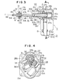
- Figs. 3 through 6 show the construction of the device V for adjusting the inclination of the light axis in detail, wherein the follower section Vl comprises a mounting 47, ball joint 17 and connecting rod 16, said mounting 47 being made of synthetic resin and having a pair of elastic engagement pieces 45 at the front end thereof, a spherical through-hole 46 formed therein, and a pair of slits 47A, 47A cut off in the axial direction thereof at its end portion opposite to that one at which the engagement pieces 45, 45 are located; said ball joint 17 having a spherical outer face corresponding to the spherical through-hole 46 in the mounting 47, projected pins 17A, 17A which are engaged with the slits 47A, 47A when the ball joint 17 is snapped into the through-hole 46, and a threaded through-hole 48 formed therein; and said connecting rod 16 having a threaded portion 16C which is screwed through the through-hole 48 in the ball joint 17, a driver recess 16d which is
- the follower section Vl is attached to the headlamp 1 by fitting the engagement pieces 45, 45 of the mounting 47 into a through-hole lb in the bracket lB located on the side of the headlamp.
- the driver section V2 comprises a housing 21 which is formed by a casing 21A and a cover 21B detachably attached to the casing 21A, and a motor 23, deceleration mechanism 24, hollow gear 27, cylindrical member 28, piston rod 30 and the like which are housed in the housing 21, respectively.
- the driver section V2 is fixed to the bracket 2 when the casing 21A is fixed to the bracket 2 by inserting a bolt 50 into a through-hole 21a of the casing 21A and into another one (not shown) of the bracked 2 which corresponds to the through-hole 21a of the casing 21A, and then screwing a nut 51 onto the bolt 50.
- a cylindrical portion 21C provided with a through-hole 21b, on the inner face of which is formed a female screw thread, is arranged at the upper front wall of the casing 21A, passing through this upper front wall.
- the hollow gear 27 is made cylindrical as a whole and has a worm gear 27b and collar-like spur gear 27c formed on the outer circumferential face while it also has a pair of sliding guide recesses 27a, 27a formed along its axial direction on its inner circumferential face.
- One end of the hollow gear 27 is fitted into a circular recess 21d on the cylindrical portion 21C of the casing 21A, while the other end thereof into a circular recess 21e of the cover 21B which corresponds to the recess 21d of the casing 21A, so that the hollow gear 27 can be supported, rotatable, by the housing 21 through the recesses 21d, 21e.
- the cylindrical member or body 28 has a male screw thread 28a formed on the outer circumferential face thereof and screwed into the female-screw-threaded through-hole 21b of the cylindrical portion 21C, and it also has a pair of engaging projections 28b, 28b which are slidably engaged with the sliding guide recesses 27a, 27a of the hollow gear 27. Therefore, the cylindrical body 28 is projected from the housing 21 at a part of its front end, passing through the female-screw-threaded throught-hole 21b, while located in the hollow gear 27 at its back end, and its engaging projections 28b, 28b are slidably engaged with the sliding guide recesses 27a, 27a.
- the piston rod 30 comprises a main portion 30B rotatably fitted into the cylindrical body 28, and a small-diameter portion 30C at that end thereof which is projected from one end of the cylindrical body 28.
- the piston 30 is inserted into.the cylindrical body 28, with the small-diameter portion 30C thereof located at the top, until a large-diameter portion 30A thereof strikes against the end face of the other end of the cylindrical body 28, and a clip 31 is fitted onto and engaged with the small-diameter portion 30C which is projected from the one end of the cylindrical body 28, so that the piston 30 can be supported by the cylindrical body 28 to rotate in relation to the cylindrical body 28 but move in the axial direction thereof together with the cylindrical body 28.
- the large-diameter portion 30A of the piston rod 30 is provided with a spherical socket 30b in which the ball portion 16a of the connecting rod 16 is received, and slits 30D, 30D cut off along the axis thereof from the opening side of the spherical socket 30b.
- the ball portion 16a of the connecting rod 16 is received in the spherical socket 30b in such a way that the projected pins 16b, 16b on the ball portion 16a are engaged with the slits 30D, 30D.
- the connecting rod 16 rotates together with the piston rod 30 and they form a universal coupling means U which can swing between them.
- the motor 23 is fixed to the inner wall of the casing 21A and a worm gear 25 is fixed to the rotating shaft 23A of the motor 23.
- the worm gear 25 is engaged with a wheel gear 54 of a gear body 26 which is formed by the wheel gear 54 and a spur gear 53, and forms the deceleration mechanism 24 together with these wheel and spur gears 54 and 53.
- the gear body 26 is rotatably supported by a shaft 52 embedded in the casing 21A, and the spur gear 53 is engaged with the spur gear 27c of the hollow gear 27.
- Numeral 36 represents a potentiometer fixed to the casing 21A
- numeral 35 denotes a wheel gear fixed to a rotation shaft 36A of the potentiometer 36.
- the wheel gear 35 is engaged with the worm gear 27b on the outer circumferential face of the cylindrical body 28.
- the potentiometer 36 forms a position detecting means for generating electric signal responsive to the rotation amount of the cylindrical body 28 when the rotation amount of the cylindrical body 28 is transmitted to the rotation shaft 36A via the hollow and wheel gears 27, 35 to rotate the rotation shaft 36A.
- the so-called aiming adjustment for adjusting initial light axis at the time of attaching the headlamp 1 to the car body through the bracket 2 is carried out as described below.
- This hand-operated aiming adjustment is carried out by advancing an adjusting tool such as the driver 49 to the connecting rod 16 from the front side of the headlamp 1.
- an adjusting tool such as the driver 49
- the connecting rod 16 is carried out from the front side of the headlamp 1.
- the hand-operated aiming adjustment according to the present invention makes it unnecessary to open the bonnet at the time of the adjusting work, thereby guaranteeing excellent workability and safety.
- the levelling adjustment of the light axis which changed depending upon the carrying conditions of the car is achieved as described below.
- the driver When the inclination of the light axis of the headlamp 1 is changed by a carrying condition, the driver recognezes the change of the inclination of the light axis, operates an operating means (not shown) located on the side of the driver's seat, and selects current flow supplied to the motor 23, depending upon whether the light axis is directed too upward or downward, to thereby rotate the motor 23 in normal or reverse direction.
- the motor 23 rotates, its rotation is transmitted to the hollow gear 27, described above, and the cylindrical body 28 is rotated to togetherer with the hollow gear 27.
- the rotating angle of the hollow gear 27 is proportional to the forward or backward shifted amount of the piston rod 30, and the potentiometer 36 can pick up the amount of rotating angle of the hollow gear 27 as an electric signal.
- This electric signal can teach us the inclined amount of the light axis practically caused between the initially set light axis and the shifted one in relation to the car body.
- the electric signal can also be used in displaying whether the light axis has been adjusted upward or downward in relation to the car body from its initially set position, and automatically controlling the inclination of the light axis to its initially set position when its adjusted amount has been recognized and the carrying condition has returned to the initial one.
- Figs. 7 and 8 show a second example of the light axis adjusting device V, wherein same parts as those in the first embodiment will be represented by same numerals and description on these parts will be omitted.
- the light axis adjusting device V comprises the follower section VI attached to the bracket lB, and the driver section V2 attached to the bracket 2, said follower and driver sections being connected to each other by means of the universal coupling means U.
- the follower section V1 comprises the mounting 47 fixed to the bracket lB; a ball joint 117 made spherical to correspond to the inner spherical circumference of the through-hole 46 in the mounting 47 and having a through-hole 148 formed therein; and a connecting rod 116 passing through the through-hole 148 in the ball joint l17 and having the ball joint 117 fixed thereon, said connecting rod 116 further having a driver recess 116d which is formed on the end face of one end thereof located on the front side of the headlamp 1 and into which the driver 49 is to be inserted to adjust the inclination of the light axis of the headlamp 1, and a ball portion 116a which is formed at the ofher end thereof, having a pair of projected pins 116b, 116b on its outer circumferential face.
- the ball joint 117 is rotated together with the connecting rod 116 when the latter rotates.
- the ball joint 117 is adapted to freely rotate in relation to the mounting 47 and the mounting 47 therefore allows the connecting rod 116 to freely rotate but move together with'the mounting 47 in the axial direction of the connecting rod 116.
- the ball joint 117 may be formed integral to the connecting rod 116.
- the driver section V2 comprises the housing 21 and motor 23, deceleration mechanism 24, hollow gear 27, cylindrical body 28, a piston rod 130, screw rod 154 and the like housed in the housing 21.
- the motor 23 and deceleration mechanism 24 are not shown in Figs. 7 and 8, the system of transmitting power to finally rotate-the hollow gear 27 is quite same as in the first embodiment.
- the casing 21A is provided with the female-screw-threaded through-hole 21b and circular recess 21d at its cylindrical portion 21C.
- the recess 21g is formed at the front end of the casing 21A, and flat faces 21f, 21f which are parallel to the axis are formed on the inner circumferential face of the recess 21g.
- the piston rod 130 is made cylindrical and comprises a main portion 130B rotatably fitted into the cylindrical body 28, a large-diameter portion 130A extended from one end of the cylindrical body 28 and arranged in the recess 21g, and a small-diameter portion 130C formed at that end of the piston rod 130 which is extended from the other end of the cylindrical body 28.
- the piston rod 130 further includes a female-screw-thread 130D formed on the inner circumferential face, and flat faces 130a, 130a formed on its large-diameter portion 130a, corresponding to the flat faces 21f, 21f of the recess 21g, said large-diameter portion 130A having a contour substantially same as the inner circumference of the recess 21g.
- the clip 31 is fitted onto the small-diameter portion 130C of the piston rod 130 extended from that end of the cylindrical body 28 which is opposite to the large-diameter portion 130A thereof.
- the piston rod 130 can be thus supported by the cylindrical body 28 in such a way that the cylindrical body 28 is allowed to freely rotate in relation to the piston rod 130 but move together with the piston rod 130 in the axial direction.
- the screw rod 154 has a male screw thread 154A formed on its outer circumferential face and screwed into the female screw thread 130D of the piston rod 130.
- the screw rod 154 also has a large-diameter portion 154B formed at its front end which is extended from one end of the piston rod 130.
- the large-diameter portion 154B is provided with a spherical socket 131b in which the ball portion 116a of the connecting rod 116 is received, and slits 131D, 131D which are cut off from the opening side of the spherical socket 131b along the axial direction of the screw rod 154.
- the ball portion 116a of the connecting rod 116 is received in the spherical socket 131b in such a way that the projected pins 116b, 116b on the ball portion 116a are engaged with the slits 131D, 131D.' Therefore, the donnecting rod 116 is rotated together with the screw rod 154, and the universal coupling means U is formed, swingable between the both members 116 and 154.
- the aiming adjustment will be carried out as follows, using the second example of the device V for adjusting the inclination of the light axis which is arranged as described above.
- the headlamp 1 which is connected to the ball joint 117 via the ball joint means 144 including the ball joint 117 and mounting 47 is swung forward and backward around the fulcrum mechanism 3 to adjust its light axis up and down in relation to the car body and return it to its initially set position.
- the adjusting tool 49 can be inserted into the headlamp 1 from the front side thereof.
- the levelling adjustment will be carried out as described below.
- the driver When the inclination of the light axis of the headlamp 1 is changed by some carrying condition of the car, the driver recognizes the change of the inclination of the light axis, operates an operating means (not shown) located on the side of the driver's seat, and selects the rotating direction of the motor 23 similarly to the case of the first embodiment, according to whether the light axis is directed too upward or downward, to thereby rotate the hollow gear 27 together with the cylindrical body 28.
- the cylindrical body 28 When the cylindrical body 28 is rotated, it is forced by the female-screw-threaded through-hole 21b of the casing 21A to move forward and backward, according to the rotating direction of the motor 23, and the piston rod 130 is shifted forward and backward together with the cylindrical body 28.
- this shift is transmitted to the headlamp 1 through the ball joint means 144 and the headlamp 1 is thus swung forward and backward around the fulcrum mechanism 3 only by the amount of this shift to thereby adjust its light axis upward and downward in relation to the car body.
- the light axis of the headlamp relative to the objects ahead and outside the car is changed from its initially set position by some carrying condition of the car, therefore, it can be returned to its initially set position by determining the amount of the above-mentioned shift.
- the potentiometer 36 can be provided, engaging the wheel gear 35 with the worm gear 27 of the hollow gear 27, and the amount of rotating angle of the hollow gear 27 can be picked up as an electric signal from the potentiometer 36, even with this second embodiment and same as in the case of the first embodiment.
- the universal coupling means U has been formed by the ball joint 16a (or 116a) located on the side of the connecting rod 16 (or 116), and by the spherical socket 30b (or 131b)located on the side of the piston rod 30 or screw rod 154 in both cases of the first and second embodiments, the ball joint 16a (or 116a) and spherical socket 30b (or 131b) may be changed in their position, the ball joint to the position of the spherical socket while the spherical socket to the position of the ball joint.
Landscapes
- Engineering & Computer Science (AREA)
- Mechanical Engineering (AREA)
- Lighting Device Outwards From Vehicle And Optical Signal (AREA)
Applications Claiming Priority (4)
| Application Number | Priority Date | Filing Date | Title |
|---|---|---|---|
| JP12616583U JPS6034031U (ja) | 1983-08-16 | 1983-08-16 | 前照灯光軸調整装置の連結構造 |
| JP126165/83U | 1983-08-16 | ||
| JP132167/83U | 1983-08-29 | ||
| JP13216783U JPS6043446U (ja) | 1983-08-29 | 1983-08-29 | ヘツドランプの光軸調整装置 |
Publications (3)
| Publication Number | Publication Date |
|---|---|
| EP0133576A2 true EP0133576A2 (de) | 1985-02-27 |
| EP0133576A3 EP0133576A3 (en) | 1987-09-16 |
| EP0133576B1 EP0133576B1 (de) | 1991-05-15 |
Family
ID=26462386
Family Applications (1)
| Application Number | Title | Priority Date | Filing Date |
|---|---|---|---|
| EP84109453A Expired EP0133576B1 (de) | 1983-08-16 | 1984-08-08 | Vorrichtung zum Einstellen der optischen Achse eines Autoscheinwerfers |
Country Status (3)
| Country | Link |
|---|---|
| US (1) | US4524407A (de) |
| EP (1) | EP0133576B1 (de) |
| DE (2) | DE133576T1 (de) |
Cited By (3)
| Publication number | Priority date | Publication date | Assignee | Title |
|---|---|---|---|---|
| FR2631295A1 (fr) * | 1988-05-10 | 1989-11-17 | Koito Mfg Co Ltd | Dispositif d'inclinaison d'un phare de vehicule |
| AT518068B1 (de) * | 2016-02-05 | 2017-07-15 | Zkw Group Gmbh | Fahrzeug-Scheinwerfer und Verfahren zum Bestimmen der Nullposition einer Spiegeleinrichtung in dem Fahrzeug-Scheinwerfer |
| EP2642190A3 (de) * | 2012-03-23 | 2017-10-25 | Ichikoh Industries, Ltd. | Montierstruktur einer Fahrzeugkomponente |
Families Citing this family (27)
| Publication number | Priority date | Publication date | Assignee | Title |
|---|---|---|---|---|
| US4689725A (en) * | 1984-10-31 | 1987-08-25 | Koito Manufacturing Co., Ltd. | Aiming device for automobile head lamp |
| DE3525618A1 (de) * | 1985-07-18 | 1987-01-22 | Bosch Gmbh Robert | Scheinwerfer fuer kraftfahrzeuge |
| DE3531959A1 (de) * | 1985-09-07 | 1987-03-19 | Bosch Gmbh Robert | Leuchtweiteregelungs-einrichtung fuer kraftfahrzeug-scheinwerfer |
| US4674018A (en) * | 1985-10-31 | 1987-06-16 | Ryder Internation Corporation | Headlamp adjusting mechanism |
| US4709306A (en) * | 1985-12-23 | 1987-11-24 | Chrysler Motors | Remote adjusting means for a vehicle headlamp |
| US4712164A (en) * | 1986-01-30 | 1987-12-08 | General Motors Corporation | Vehicle headlamp assembly |
| US4665469A (en) * | 1986-03-07 | 1987-05-12 | Eaton Corporation | Headlight adjuster gear assembly |
| US4713739A (en) * | 1987-01-06 | 1987-12-15 | Ryder International Corporation | Clam shell gear box housing and retainer |
| JPH0423709Y2 (de) * | 1987-02-26 | 1992-06-03 | ||
| US4757428A (en) * | 1987-03-03 | 1988-07-12 | Ryder International Corporation | Headlamp mounting assembly |
| US4731707A (en) * | 1987-05-04 | 1988-03-15 | General Motors Corporation | Vehicle headlamp assembly |
| US4893219A (en) * | 1988-09-30 | 1990-01-09 | Ryder International Corporation | Headlamp adjusting mechanism |
| US4939945A (en) * | 1989-04-13 | 1990-07-10 | Ryder International Corp. | Gearbox drive system with plastic output gear |
| GB2232237A (en) * | 1989-05-19 | 1990-12-05 | Ford Motor Co | Headlight adjustment |
| EP0468920A1 (de) * | 1990-07-26 | 1992-01-29 | Saia Ag | Positioniervorrichtung |
| IT1241317B (it) * | 1990-11-09 | 1994-01-10 | Carello Spa | Proiettore anabbagliante per veicoli |
| US5193905A (en) * | 1991-12-13 | 1993-03-16 | Elco Industries, Inc. | Vehicle headlamp adjuster |
| US5321589A (en) * | 1992-08-07 | 1994-06-14 | Harada Kogyo Kabushiki Kaisha | Apparatus for controlling irradiation angle of a headlamp light |
| US5394318A (en) * | 1993-03-31 | 1995-02-28 | Harada Kogyo Kabushiki Kaisha | Device for adjusting and controlling the optical axis of a headlamp |
| DE4420779C1 (de) * | 1994-06-15 | 1995-06-22 | Hella Kg Hueck & Co | Einstellsystem für einen Reflektor eines Fahrzeug-Scheinwerfers |
| DE19646282A1 (de) * | 1996-11-11 | 1998-05-14 | Bosch Gmbh Robert | Vorrichtung zum Verstellen der Leuchtweite von Scheinwerfern |
| US7004607B2 (en) * | 2003-10-23 | 2006-02-28 | Asyst Technologies, Llc | Motorized lamp adjuster |
| DE102008063752B4 (de) * | 2008-01-11 | 2018-01-25 | Schaeffler Technologies AG & Co. KG | Kolbenstangenanbindung |
| DE102008024377A1 (de) * | 2008-05-20 | 2009-11-26 | Automotive Lighting Reutlingen Gmbh | Vorrichtung und Verfahren zur Ausrichtung einer Leuchteinheit |
| EP2213513B1 (de) | 2009-01-28 | 2016-09-07 | Automotive Lighting Italia S.p.A. | Vorrichtung zur Einstellung der Neigung einer optischen Achse einer Beleuchtungsvorrichtung für Fahrzeuge |
| KR101728552B1 (ko) * | 2010-12-21 | 2017-04-19 | 엘지이노텍 주식회사 | 레벨링 모터 |
| DE102021104945A1 (de) * | 2021-03-02 | 2022-09-22 | HELLA GmbH & Co. KGaA | Beleuchtungsvorrichtung für ein Fahrzeug |
Family Cites Families (10)
| Publication number | Priority date | Publication date | Assignee | Title |
|---|---|---|---|---|
| DE1958759C3 (de) * | 1969-11-22 | 1979-07-12 | Robert Bosch Gmbh, 7000 Stuttgart | Vorrichtung zur Steuerung der Leuchtweite von Kraftfahrzeug-Scheinwerfern |
| DE2053660A1 (de) * | 1970-10-31 | 1972-05-10 | Rau Swf Autozubehoer | Fahrzeugscheinwerfer mit Betätigungsvorrichtung |
| JPS5623152Y2 (de) * | 1976-11-17 | 1981-05-30 | ||
| JPS5623697Y2 (de) * | 1977-09-26 | 1981-06-03 | ||
| IT1107154B (it) * | 1978-02-27 | 1985-11-25 | Fiat Spa | Servocomando elettromeccanico |
| DE2847908C3 (de) * | 1978-11-04 | 1981-04-30 | Ford-Werke Ag, 5000 Koeln | Blinkleuchte-Scheinwerfer-Befestigung in Kraftfahrzeugkarosserien |
| DE2847990C3 (de) * | 1978-11-06 | 1981-04-02 | Ford-Werke AG, 5000 Köln | Einstelleinrichtung für Scheinwerfer von Kraftfahrzeugen |
| FR2496572A1 (fr) * | 1980-12-23 | 1982-06-25 | Bosch Gmbh Robert | Dispositif de reglage a moteur electrique pour phare de vehicule automobile |
| DE3467990D1 (en) * | 1983-03-22 | 1988-01-21 | Ichikoh Industries Ltd | Device for adjusting the inclination of the light axis of headlamps of a motor vehicle |
| JPS6099703U (ja) * | 1983-12-14 | 1985-07-08 | 株式会社小糸製作所 | 車輛用前照灯における光軸調整装置 |
-
1984
- 1984-08-08 DE DE198484109453T patent/DE133576T1/de active Pending
- 1984-08-08 DE DE8484109453T patent/DE3484579D1/de not_active Expired - Lifetime
- 1984-08-08 EP EP84109453A patent/EP0133576B1/de not_active Expired
- 1984-08-10 US US06/639,318 patent/US4524407A/en not_active Expired - Fee Related
Cited By (5)
| Publication number | Priority date | Publication date | Assignee | Title |
|---|---|---|---|---|
| FR2631295A1 (fr) * | 1988-05-10 | 1989-11-17 | Koito Mfg Co Ltd | Dispositif d'inclinaison d'un phare de vehicule |
| EP2642190A3 (de) * | 2012-03-23 | 2017-10-25 | Ichikoh Industries, Ltd. | Montierstruktur einer Fahrzeugkomponente |
| AT518068B1 (de) * | 2016-02-05 | 2017-07-15 | Zkw Group Gmbh | Fahrzeug-Scheinwerfer und Verfahren zum Bestimmen der Nullposition einer Spiegeleinrichtung in dem Fahrzeug-Scheinwerfer |
| AT518068A4 (de) * | 2016-02-05 | 2017-07-15 | Zkw Group Gmbh | Fahrzeugscheinwerfer und Verfahren zum Bestimmen der Nullposition einer Spiegeleinrichtung in dem Fahrzeugscheinwerfer |
| US10018319B2 (en) | 2016-02-05 | 2018-07-10 | Zkw Group Gmbh | Method for determining the zero position of a mirror device of a vehicle headlight |
Also Published As
| Publication number | Publication date |
|---|---|
| EP0133576B1 (de) | 1991-05-15 |
| US4524407A (en) | 1985-06-18 |
| DE133576T1 (de) | 1985-06-05 |
| DE3484579D1 (de) | 1991-06-20 |
| EP0133576A3 (en) | 1987-09-16 |
Similar Documents
| Publication | Publication Date | Title |
|---|---|---|
| US4524407A (en) | Device for adjusting the inclination of the light axis of a headlamp for motor vehicles | |
| EP1675751B1 (de) | Motorisierte lampeneinstellvorrichtung | |
| US4574334A (en) | Device for adjusting the inclination of the light axis of headlamps of a motor vehicle | |
| US5240284A (en) | Steering column assembly with horizontal position adjustment mechanism | |
| US5259257A (en) | Power slider | |
| US5070433A (en) | Headlight for a motor vehicle having an adjustable motor-driven reflector | |
| US20080130301A1 (en) | Vehicle Lamp | |
| US5828504A (en) | Exterior rearview mirror for a vehicle | |
| GB2109082A (en) | A headlamp for vehicles especially for motor vehicles | |
| EP0716954A2 (de) | Vorrichtung zum Einstellen der optischen Achse eines Scheinwerfers | |
| GB2253900A (en) | Headlamp levelling mechanism | |
| US5544023A (en) | Horizontal zero indicator assembly | |
| US5414602A (en) | Vehicle headlamp adjuster with pivoting housing | |
| US5285695A (en) | Steering wheel and deflection unit for a vehicle, in particular for a motor vehicle | |
| EP0402133A1 (de) | Lenksaüleneinheit mit Vorrichtung zum Einstellen der horizontalen Lage | |
| EP0463563A1 (de) | Elektrisch fernbedienbarer Rückspiegel | |
| TWI785943B (zh) | 車燈之水平光形調整系統 | |
| KR0120425Y1 (ko) | 자동차용 엑티브 헤드라이트의 각도 조절장치 | |
| DE29916707U1 (de) | Automatisch schwenkende Scheinwerferstruktur | |
| JPS6015202Y2 (ja) | ヘツドランプの光軸調整装置 | |
| JPH10258677A (ja) | オートレベラーと光軸調整装置が装備された車両用灯具 | |
| JP2517581Y2 (ja) | 車両用灯具の光軸調整装置 | |
| KR100213500B1 (ko) | 자동차용 아웃 사이드미러 자동조정장치 | |
| KR0141033B1 (ko) | 조향각 적응형 전조등제어장치 | |
| KR200144571Y1 (ko) | 자동차의 전조등 구동장치 |
Legal Events
| Date | Code | Title | Description |
|---|---|---|---|
| PUAI | Public reference made under article 153(3) epc to a published international application that has entered the european phase |
Free format text: ORIGINAL CODE: 0009012 |
|
| AK | Designated contracting states |
Designated state(s): DE FR GB |
|
| EL | Fr: translation of claims filed | ||
| DET | De: translation of patent claims | ||
| 17P | Request for examination filed |
Effective date: 19860404 |
|
| PUAL | Search report despatched |
Free format text: ORIGINAL CODE: 0009013 |
|
| AK | Designated contracting states |
Kind code of ref document: A3 Designated state(s): DE FR GB |
|
| 17Q | First examination report despatched |
Effective date: 19890915 |
|
| GRAA | (expected) grant |
Free format text: ORIGINAL CODE: 0009210 |
|
| AK | Designated contracting states |
Kind code of ref document: B1 Designated state(s): DE FR GB |
|
| REF | Corresponds to: |
Ref document number: 3484579 Country of ref document: DE Date of ref document: 19910620 |
|
| ET | Fr: translation filed | ||
| PLBE | No opposition filed within time limit |
Free format text: ORIGINAL CODE: 0009261 |
|
| STAA | Information on the status of an ep patent application or granted ep patent |
Free format text: STATUS: NO OPPOSITION FILED WITHIN TIME LIMIT |
|
| 26N | No opposition filed | ||
| PGFP | Annual fee paid to national office [announced via postgrant information from national office to epo] |
Ref country code: GB Payment date: 19920724 Year of fee payment: 9 Ref country code: FR Payment date: 19920724 Year of fee payment: 9 |
|
| PGFP | Annual fee paid to national office [announced via postgrant information from national office to epo] |
Ref country code: DE Payment date: 19920930 Year of fee payment: 9 |
|
| PG25 | Lapsed in a contracting state [announced via postgrant information from national office to epo] |
Ref country code: GB Effective date: 19930808 |
|
| GBPC | Gb: european patent ceased through non-payment of renewal fee |
Effective date: 19930808 |
|
| PG25 | Lapsed in a contracting state [announced via postgrant information from national office to epo] |
Ref country code: FR Effective date: 19940429 |
|
| PG25 | Lapsed in a contracting state [announced via postgrant information from national office to epo] |
Ref country code: DE Effective date: 19940503 |
|
| REG | Reference to a national code |
Ref country code: FR Ref legal event code: ST |