EP1675792B1 - Produktträger und transportvorrichtung - Google Patents
Produktträger und transportvorrichtung Download PDFInfo
- Publication number
- EP1675792B1 EP1675792B1 EP04775451A EP04775451A EP1675792B1 EP 1675792 B1 EP1675792 B1 EP 1675792B1 EP 04775451 A EP04775451 A EP 04775451A EP 04775451 A EP04775451 A EP 04775451A EP 1675792 B1 EP1675792 B1 EP 1675792B1
- Authority
- EP
- European Patent Office
- Prior art keywords
- carrier
- conveyor
- wheel units
- track
- arms
- Prior art date
- Legal status (The legal status is an assumption and is not a legal conclusion. Google has not performed a legal analysis and makes no representation as to the accuracy of the status listed.)
- Expired - Lifetime
Links
Images




Definitions
- the present invention relates to a product carrier, moveable along a conveyor track in a conveyor arrangement, and designed as a trolley, which has at least two wheel units which are designed to be moved along the conveyor track, and a carrier arm which is suspended from each wheel unit and which is provided with carrier members for the products that are to be conveyed.
- the present invention also relates to a conveyor arrangement comprising a first conveyor and at least a second conveyor together with a number of product carriers designed as trolleys which are moveable along the conveyors for moving products, the first conveyor comprising a continuous track, and the trolleys having wheel units designed to run along the track, and the second conveyor comprising a chain conveyor in the form of a loop of links designed with members for receiving and holding during transport of the trolleys, said holding members being situated at a selected spacing interval from one another.
- the object of the present invention is to eliminate the aforementioned disadvantages in conveying more than one object or heavier objects in one and the same product carrier.
- Said object is achieved by means of a product carrier which is characterized in that the carrier arms are connected to one another by means of a positioning mechanism, which maintains a selected essential distance between the wheel units regardless of the inclination of the track.
- Said object is also achieved by means of a conveyor arrangement which is characterized in that the wheel units have suspended carrier arms which are connected to one another by means of a positioning mechanism for maintaining a selected positional relationship between the wheel units, so that the wheel units on the whole maintain an axial distance from one another which largely corresponds to said spacing interval.
- the construction of the product carrier 1 according to the first embodiment will first be described with reference to Figs. 1 to 4.
- This forms part of a conveyor arrangement which also includes a conveyor track 2, along which the product carrier is intended to move in order to move products between different positions along the track.
- the product carrier is designed as a trolley having two wheel units 3, 4, which constitute the connection between the trolley and the conveyor track.
- the carrier members are designed as a number of loops 7 for hangers, shackles or clips and/or a suspended, pivotally supported hook 8.
- the carrier arms 5, 6 are connected to one another by a mechanical positioning mechanism 9 arranged in a holder 10, in which the carrier arms 5, 6 are pivotally supported.
- the holder 10 supports the carrier members 7, 8.
- the positioning mechanism 9 consists of a parallel guide mechanism which is designed to permanently maintain a largely constant angular relationship between the carrier arms 5, 6, and thereby also a specific axial distance a between the wheel units 3, 4, but with minor variations, as will be explained in more detail below.
- the mechanism also maintains an unaltered angular relationship, in the example a parallel relationship, between the connecting axis 11 of the wheel units on the one hand and the axis of symmetry 12 of the holder on the other, viewed in the plane of projection according to Fig. 1.
- Each wheel unit 3, 4 comprises two rollers 13, 14 situated with an interval between them, the rollers in the example shown being rigidly connected to one another by means of a waist section in the form of an axle casing 15.
- the rollers and the axle casing 15 are supported so that they can rotate about a shaft 16, which is firmly connected to each carrier arm 5, 6 and in practice may comprise a curved section of the carrier arm, which is advantageously made, for example, of metal such as a steel rod, light alloy rod or light alloy tube, whilst other parts of each wheel unit are made of a high-strength plastic material.
- the rollers 13, 14 are designed to run in a roller track which is formed by the conveyor track 2 and is in practice formed as a profile, as shown in Fig. 2, as a straight section of the conveyor track, the geometric axes of rotation 17, 18 of the wheel units, which are formed by the shaft 16, being parallel to one another.
- the parallel guide mechanism 9 comprises a gearwheel mechanism having three gearwheels 19, 20, 21 rotatably supported in the holder.
- the two outer gearwheels 19, 20 intermesh with an intermediate gearwheel 21, the outer gearwheels having the same diameter as one another and each being connected to one of the carrier arms 5, 6, so that they are turned together by swiveling movements of the carrier arms in the plane of projection according to Fig. 1.
- the carrier arms are at the bottom bent at right angles into a through-hole in the two outer gearwheels, in order to robustly transmit the load from the products carried via the carrier members 7, 8 and via the arms to the wheel units 3, 4.
- the carrier arms 5, 6 are at the top suspended and articulated in the wheel units 3, 4 and are firmly articulated in the holder 10 by way of the gearwheels 19, 20 allows them to perform a coordinated oscillating movement, which will be described in more detail below.
- the holder 10 is designed as a box-shaped housing with broad, transverse essentially plane end walls 22, 23, which form stop surfaces or buffers when lining up multiple trolleys in one conveyor arrangement.
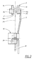
- Fig. 1 and 3 show that the one carrier member 8 in the form of a hook 24 is suspended in a central hole 21 a in the intermediate gearwheel 21.
- the carrier member 8 is advantageously intended for heavier objects, and at its bottom end may have a holding arrangement for objects, for example a hook or clip.
- Fig. 3 furthermore shows that the carrier arms 5 (the carrier arm 6 is hidden) are angled off from a straight vertical line, so that the center of gravity of the load ends up symmetrically in a vertical line of symmetry or a plane of symmetry 25.
- the conveyor track in addition to the roller track 2a for each roller 13, 14 the conveyor track also comprises lateral guide tracks 2b, which interact with one side face 13a, 14a of each roller in order to position the wheel units 3, 4 in the track.
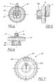
- Fig. 4 to 7 show a practical embodiment of the outer gearwheels 19, see Figs 4 to 6, and of the intermediate gear, see Fig. 7.
- the outer gearwheels have a drive member 26 in which the lower end of each carrier arm 5, 6 is held and which drives the gearwheel in the swiveling movement of the carrier arm about its wheel unit.
- the outer gearwheels 19 have a specially shaped central opening 27, in which the bent-over end section 28 of the carrier arm 5 pushes. More specifically, the opening is essentially circular at the end where the carrier arm is inserted, but widens out conically viewed in a plane at right angles to the main extent of the carrier arm.
- the gearwheels 19-21 moreover have bearing sections 19a, 21 a for rotatable support in corresponding sections in the holder 10. Also visible from Fig.
- Fig. 8 and 9 show a situation in which the product carrier 1 is situated on a curve of the conveyor track 2 of the conveyor arrangement.
- the fact that the carrier arms 5, 6 are allowed, as described above, to twist within a certain range about their longitudinal axis means that the two carrier wheels 3, 4 can be angled, that is to say their axes of rotation 17, 18 are able to deviate to a relatively large extent from a position in which they are parallel with one another, partly for cornering on this track and partly to allow a minor adjustment of the axial distance a, in Fig. 9 a small reduction of a.
- the distance a here relates to the distance between the axes 17, 18 at their symmetrical midpoint 17a, 18a on the axle casing 15.
- a corresponding angling of the axes of rotation 17, 18 of the wheel units in an opposite direction is permitted when cornering on a curve in the opposite direction.
- the pivot center 58, for the axes of rotation 17, 18 lies outside the center of symmetry of the wheel units 3, 4, which gives the modified axial distance, which is important in conveyors of the chain conveyor type, see below.
- Fig. 12 shows the parallel function of the product carrier according to the invention on a steeply inclined section of the conveyor track 2.
- the parallel function serves to keep the carrier arms 5, 6 in an unaltered angular position relative to one another, in the example essentially parallel to one another, which affords a retained center-to-center distance a between the wheel units 3, 4.
- the axis of symmetry 12 of the holder is substantially parallel to the track 2 even on an inclined section.
- a controlled relative position of the holder 10 and the carrier members 7 is thereby obtained at all times, which gives an even load distribution of the carrier arms 5, 6 and the wheel units 3, 4.
- the end walls 22, 23 are thereby turned in the direction of the conveyor track, with the result that in a queue of product carriers the end walls are turned towards one another and thereby function as buffers with no risk of getting caught between the trolleys.
- Fig. 13 shows how the product carrier on a reverse incline is adjusted whilst retaining the essential parallelism between the carrier arms 5, 6 in that the outer gearwheels together intermesh with the intermediate gearwheel 21 and maintain the axial distance a between the wheel units 3, 4.
- the permanent intermeshing engagement with the intermediate gearwheel 20 keeps the outer gearwheels 19, 21 constantly in the same turning position relative to one another that produces the unaltered axial distance a.
- Fig. 14 shows a section of a conveyor arrangement or installation for conveying products, which may be all conceivable types of objects, for example mats 32.
- the conveyor arrangement may be of a type, for example, in which a plurality of trolleys 1, only one of which is shown, are conveyed along a main line (not shown) up to a number of branch lines 33, 34, only one of which is shown, where the trolleys are switched over to each branch line for specific treatments in a work station, before being brought back to the main line.
- An example of such an installation is disclosed by US 4,817,778 A .
- the product carriers 1 are switched to the branch line, which in the example comprises two types of conveyor 33, 34 and a transfer unit 35 for transferring the trolleys from one conveyor 22 to the other conveyor 34.
- the one comprises the aforementioned roller track in the form of a suitably shaped profile section as previously described, which forms rolling surfaces for the rollers 13, 14 of the wheel units 3, 4 and guide faces for lateral guiding of the rollers.
- the second conveyor 34 in the example shown comprises a conveyor chain, which in an advantageous example may have the same construction as in the earlier patent specification, suitably in the form of a closed loop.
- the conveyor chain comprises a plurality of links 36, 37, which by way of joint pins 38, 39 are articulated to one another for an articulated movement or swivel movement in a specific plane, but are guided by interacting slide surfaces so that reciprocal movement between the links in other planes is minimized.
- the links consist of two types, which will hereinafter be referred to as carrier links 36 and intermediate links 37.
- the chain conveyor 34 is designed to receive and to hold the transported and stationary trolleys and to deliver them through interaction with their wheel units in a known manner according to the earlier patent specification.
- the carrier links have holding members or driver members, which are designed to receive and to hold the transported wheel units 3, 4 of the trolleys and to deliver them.
- these holding members comprise openings 40, which in a release position are open to the outside, but in the holding position, that is to say in the conveying position or when the conveyor is stationary at a work station, for example, ensure holding by means of a catch 60.
- the carrier links in the vicinity of the opening are of a width smaller than the interval between the rollers of the wheel units, that is to say the length of the axle casing 15, so that the wheel unit is held between the rollers 13, 14 with a clearance, which allows the wheel units 3, 4 to be angled somewhat by the aforementioned torsion of the carrier arms 5, 6.
- the first conveyor 33 on the branch line is inclined downwards towards the loading unit 35 and is open towards a third conveyor.
- the front wheel unit 4 of the trolley is held stationary by the longitudinal edge 41 of the intermediate links, which forms a stop edge against the front wheel unit 4, until the chain conveyor by means of its drive wheel 42 runs around its periphery so that the opening 40 of the next carrier link 36 comes to rest directly opposite the front gripping section of the front wheel unit, that is to say the axle casing.
- the locking mechanism 60 for the opening 40 is thereby switched to the open position, that is to say the release position so that the gripping section of the wheel unit rolls into the opening and is carried by the movement of the chain conveyor.
- the locking mechanism 60 is spring-loaded, so that it strives to block the opening by means of a catch 61. When the axle casing 15 from outside strikes against an edge of the catch, the latter is moved aside and the wheel unit can be received and held.
- each product carrier is delivered to a roller track, the catch being opened through activation.
- the wheel units 3, 4 of the trolley are positioned at an axial distance a from one another, which is selected so that it corresponds to the spacing interval b of the holding members on the carrier links, that is to say the openings. In the example shown this is equal to the distance between the nearest links, but in principle the distance may be a multiple of the distance between the carrier links. It will also be seen from Fig. 14 that, within certain limits, the parallel function creates a predefined axial distance a, that is to say the distance between the axes 17, 18 in the wheel units, irrespective of the inclination of the conveyor track 2. As has been described above, this applies on straight, that is to say linear sections of the roller track 2, for which reason the first conveyor 33 is straight in its section closest to the loading unit.
- the selected interval is precisely maintained so that the wheel units can be brought into openings 40 in the conveyor chain one at a time in the correct position.
- the trolley as a whole and the holder 1 with the carrier members 7 furthermore acquire a controlled position in that the trolley as a whole at all times maintains a geometric pattern in the form of a parallelogram having different angles depending on the inclination of the conveyor track.
- the spacing interval b is temporarily reduced, the axial distance a of the wheel units being adjusted accordingly due to the holding in the openings 40, and the torsion of the carrier arms 5, 6 described above.
- the holding of the wheel units 3, 4 is in fact adjusted with some play in order to permit this torsion.
- Fig. 15 shows one of the trolleys 1 in a position in the conveyor chain with the wheel units held in the openings 40 and the carrier arms 5, 6 parallel, so that the trolley as a whole is thereby in a controlled position with the holder 10 and the string of carrier members 7 parallel to the main extent of the conveyor chain, which gives an even load distribution between the wheel units 3, 4.
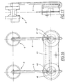
- Fig. 16 and 17 show the positioning mechanism in a second embodiment in which the gearwheel mechanism is replaced by a parallel arm 45, which connects the two carrier arms 5, 6 together by articulations 46, 47 situated at the same eccentric distance from the pivot center 48, 49 of the carrier arms.
- circular wheel-like elements are provided, which may have the same construction as the outer gearwheels 19, 20 but without toothing.
- the trolley may have the same construction as in the first embodiment, with the same facility for torsion of the carrier arms 5, 6 about their longitudinal axis.
- Figs. 18 and 19 show a third embodiment of the trolley having two parallel arms 50, 51 articulated at a distance from one another along points of articulation 52, 53 54, 55 which are situated symmetrically on each carrier arm 5, 6.
- the box-shaped holder is replaced by two buffer elements 56, 57.
- the parallel arms 50, 51 have two fixing holes for heavier objects.
- the same function is achieved in the second and third embodiments as in the first embodiment, namely positioning of the carrier arms so that the wheel units 3, 4 maintain a largely unaltered axial distance between them regardless of the angular position between the carrier arms and the conveyor track.
- the maintained axial distance can be automatically adjusted within a small range through torsion of the carrier arms 5, 6 about their longitudinal axes.
- a trolley may in principle have three or more wheel units with suspended carrier arms.
- the carrier arms may have a reciprocal angle other than 0°, that is to say they may not be parallel.
- a parallel rod may in principle be situated up against the wheel units.
- the torsional function for adjustment of the axial distance is not necessary for the basic positioning function. If the torsional function is included this may be resolved in some other way, for example by an angle joint between the upper end of the carrier arms and the axis of rotation of the wheel units.
- the movement of the trolley along other sections of the roller track, such as horizontal sections and rising sections may be achieved in various ways, for example by a drive chain which drives the trolley, for example on the one wheel unit.
Landscapes
- Chain Conveyers (AREA)
Claims (10)
- Produktträger, der entlang einer Förderstrecke (33, 34) in einer Förderanordnung bewegbar ist, und der als ein Förderkarren ausgestaltet ist, welcher zumindest zwei Radeinheiten (3, 4), die so ausgestaltet sind, dass sie entlang der Förderstrecke bewegt werden, und einen Trägerarm (5, 6) hat, der drehbar an jeder Radeinheit aufgehängt ist, und der mit Trägerelementen (7, 8) für die zu fördernden Produkte versehen ist, wobei die Trägerarme (5, 6) durch Mittel eines Positionsmechanismus (9/45, 50, 51) miteinander verbunden sind,
dadurch gekennzeichnet, dass
die Trägerarme (5, 6) drehbar in einem Halter (10) aufgehängt sind, in dem der Positionsmechanismus angeordnet ist und dass der Positionsmechanismus einen ausgewählten wesentlichen Abstand (a) zwischen den Radeinheiten (3, 4) ungeachtet der Neigung der Strecke aufrechterhält. - Produktträger nach Anspruch 1, dadurch gekennzeichnet, dass der Positionsmechanismus (9/45, 50, 51) einen parallelen Führungsmechanismus umfasst, der die Trägerarme (5, 6) im Wesentlichen parallel zueinander hält, ungeachtet der Neigung der Strecke, so dass der Abstand (a) in Relation zueinander weitgehend aufrechterhalten wird.
- Produktträger nach Anspruch 1, dadurch gekennzeichnet, dass der Positionsmechanismus (9) ein gezahntes Getriebe umfasst, das eine Anzahl von Getrieberädern (19, 20, 21) hat, die rotierbar in dem Halter (10) gelagert sind.
- Produktträger nach Anspruch 2 oder 3, dadurch gekennzeichnet, dass der Halter (10) als eine Box ausgestaltet ist, in der die Getrieberäder (19, 20, 21) drehbar gelagert sind und dass die Getrieberäder zwei äußere Getrieberäder (19, 20) umfassen, die so ausgestaltet sind, dass sie den schwenkenden Bewegungen der Trägerarme (5) folgen, und ein Zwischengetrieberad (21), welches mit den äußeren Getrieberädern ineinander greift, wobei die zwei äußeren Getrieberäder den selben Durchmesser haben.
- Produktträger nach Anspruch 2, dadurch gekennzeichnet, dass der parallele Führungsmechanismus (45, 50, 51) parallele Arme (45, 50, 51) hat, die direkt oder indirekt in den Trägerarmen (5, 6) in einem gleichmäßigen Abstand gegliedert sind.
- Produktträger nach Anspruch 1, dadurch gekennzeichnet, dass die Radeinheiten (4, 5) um ihre Rotationsachsen (17, 18) gedreht werden können, um sie auf die kurvigen Abschnitte der Förderstrecke (33, 34) einzustellen.
- Produktträger nach Anspruch 6, dadurch gekennzeichnet, dass der Abstand (a) zwischen den Radeinheiten (5, 6) innerhalb enger Grenzen variabel ist.
- Produktträger nach Anspruch 7, dadurch gekennzeichnet, dass das Drehen der Radeinheiten (3, 4) durch Torsion der Trägerarme (5, 6) um ihre längliche Achse erreicht wird.
- Eine Förderanordnung, die eine erste Förderanlage (33) und zumindest eine zweite Förderanlage (34) zusammen mit einer Anzahl von Produktträgern (1) umfasst, die als Transportkarren ausgestaltet sind, die entlang der Förderanlagen zum Bewegen der Produkte bewegbar sind, wobei die erste Förderanlage eine durchgängige Strecke umfasst, und die Förderkarren Radeinheiten (3, 4) haben, die so ausgestaltet sind, dass sie entlang der Strecke laufen, und die zweite Förderanlage eine Kettenförderanlage in der Form einer Schleife von Gelenken (36, 37) umfasst, die mit Elementen zum Empfangen und Halten der transportierten Förderkarren ausgestaltet sind, wobei die Halteelemente in einem ausgewählten Abstandsintervall (b) zueinander angeordnet sind,
dadurch gekennzeichnet, dass
die Radeinheiten (3, 4) drehbar aufgehängte Trägerarme (5, 6) haben, die miteinander durch Mittel eines Positionsmechanismus (9/45, 50, 51) zum Aufrechterhalten eines ausgewählten Positionsverhältnisses zwischen den Radeinheiten verbunden sind, so dass die Radeinheiten grundlegend einen axialen Abstand (a) voneinander aufrechterhalten, der im Wesentlichen dem Abstandsintervall (b) entspricht, und dass die Trägerarme drehbar in einem Halter (10) gelagert sind, in dem der Positionsmechanismus angeordnet ist. - Trägeranordnung nach Anspruch 9, dadurch gekennzeichnet, dass der gegenseitige axiale Abstand (a) innerhalb enger Granzen zum Einstellen von Änderungen des Abstandsintervalls (b) der zweiten Fördereinrichtung (34) variabel ist.
Applications Claiming Priority (4)
| Application Number | Priority Date | Filing Date | Title |
|---|---|---|---|
| US48170403P | 2003-09-22 | 2003-09-22 | |
| SE0348140 | 2003-09-22 | ||
| SE0302541A SE526863C2 (sv) | 2003-09-22 | 2003-09-22 | Produktbärare och transportanordning i vilken produktbärare ingår |
| PCT/SE2004/001349 WO2005028342A1 (en) | 2003-09-22 | 2004-09-20 | Product carrier and transport device |
Publications (2)
| Publication Number | Publication Date |
|---|---|
| EP1675792A1 EP1675792A1 (de) | 2006-07-05 |
| EP1675792B1 true EP1675792B1 (de) | 2007-12-12 |
Family
ID=36499719
Family Applications (1)
| Application Number | Title | Priority Date | Filing Date |
|---|---|---|---|
| EP04775451A Expired - Lifetime EP1675792B1 (de) | 2003-09-22 | 2004-09-20 | Produktträger und transportvorrichtung |
Country Status (1)
| Country | Link |
|---|---|
| EP (1) | EP1675792B1 (de) |
Families Citing this family (1)
| Publication number | Priority date | Publication date | Assignee | Title |
|---|---|---|---|---|
| CN114918979B (zh) * | 2022-06-30 | 2024-04-26 | 上海擎朗智能科技有限公司 | 一种浮动托盘及机器人 |
-
2004
- 2004-09-20 EP EP04775451A patent/EP1675792B1/de not_active Expired - Lifetime
Also Published As
| Publication number | Publication date |
|---|---|
| EP1675792A1 (de) | 2006-07-05 |
Similar Documents
| Publication | Publication Date | Title |
|---|---|---|
| US7578381B2 (en) | Product carrier and transport device | |
| CA2801621C (en) | Transport apparatus with moving trucks | |
| NL2012386B1 (nl) | Inrichting en werkwijze voor het wijzigen van de oriëntatie van slachtproducten. | |
| NL1008010C2 (nl) | Transportinrichting. | |
| CN104058122A (zh) | 落下辅助装置、填充系统以及填充辅助方法 | |
| JPS61114912A (ja) | 2重曲りコンベヤ | |
| JP2007506631A5 (de) | ||
| US6231293B1 (en) | Tipping device for emptying containers for piece goods | |
| CN107074448A (zh) | 用于运送器的、尤其用于重力运送器的活动架、运送系统和用于运行运送系统的方法 | |
| JPH07144736A (ja) | 個別搬送手段を含むエンドレス回動式のばら物品搬送装置 | |
| JPS61166416A (ja) | プラツトホーム形コンベヤ | |
| US5129506A (en) | Space conveyor for newspaper, books and magazines | |
| JP2007529385A (ja) | 転動運搬装置 | |
| US20090223779A1 (en) | Conveyor Diverter | |
| EP1675792A1 (de) | Produktträger und transportvorrichtung | |
| NL9400388A (nl) | Sorteerinrichting voor het afwerpen van goederen. | |
| JPH0764417B2 (ja) | 卵のごとき物品の受容または転送、垂直搬送および供給装置 | |
| JP2024039621A (ja) | 重量搬送能力が向上したキャリアバスケットを有するキャリアバスケット搬送装置 | |
| CZ278730B6 (en) | Conveyances of overhead transport system | |
| JP2013523564A (ja) | コンベヤ | |
| JP3086461U (ja) | 搬送装置および走行体 | |
| RU2009122653A (ru) | Транспортер | |
| CZ310000B6 (cs) | Pendlový řetězový dopravník | |
| JPS6231608A (ja) | エンドレスコンベア | |
| JPS6341337A (ja) | 製本機械用の搬送チエンユニット |
Legal Events
| Date | Code | Title | Description |
|---|---|---|---|
| PUAI | Public reference made under article 153(3) epc to a published international application that has entered the european phase |
Free format text: ORIGINAL CODE: 0009012 |
|
| 17P | Request for examination filed |
Effective date: 20060424 |
|
| AK | Designated contracting states |
Kind code of ref document: A1 Designated state(s): AT BE BG CH CY CZ DE DK EE ES FI FR GB GR HU IE IT LI LU MC NL PL PT RO SE SI SK TR |
|
| DAX | Request for extension of the european patent (deleted) | ||
| GRAP | Despatch of communication of intention to grant a patent |
Free format text: ORIGINAL CODE: EPIDOSNIGR1 |
|
| RIN1 | Information on inventor provided before grant (corrected) |
Inventor name: DAVIDSON, MATS INGVAR |
|
| GRAS | Grant fee paid |
Free format text: ORIGINAL CODE: EPIDOSNIGR3 |
|
| GRAA | (expected) grant |
Free format text: ORIGINAL CODE: 0009210 |
|
| AK | Designated contracting states |
Kind code of ref document: B1 Designated state(s): AT BE BG CH CY CZ DE DK EE ES FI FR GB GR HU IE IT LI LU MC NL PL PT RO SE SI SK TR |
|
| REG | Reference to a national code |
Ref country code: GB Ref legal event code: FG4D |
|
| REG | Reference to a national code |
Ref country code: CH Ref legal event code: EP |
|
| REG | Reference to a national code |
Ref country code: IE Ref legal event code: FG4D |
|
| REF | Corresponds to: |
Ref document number: 602004010698 Country of ref document: DE Date of ref document: 20080124 Kind code of ref document: P |
|
| REG | Reference to a national code |
Ref country code: DE Ref legal event code: R096 Ref document number: 602004010698 Country of ref document: DE Effective date: 20080124 |
|
| PG25 | Lapsed in a contracting state [announced via postgrant information from national office to epo] |
Ref country code: CH Free format text: LAPSE BECAUSE OF FAILURE TO SUBMIT A TRANSLATION OF THE DESCRIPTION OR TO PAY THE FEE WITHIN THE PRESCRIBED TIME-LIMIT Effective date: 20071212 Ref country code: LI Free format text: LAPSE BECAUSE OF FAILURE TO SUBMIT A TRANSLATION OF THE DESCRIPTION OR TO PAY THE FEE WITHIN THE PRESCRIBED TIME-LIMIT Effective date: 20071212 Ref country code: SE Free format text: LAPSE BECAUSE OF FAILURE TO SUBMIT A TRANSLATION OF THE DESCRIPTION OR TO PAY THE FEE WITHIN THE PRESCRIBED TIME-LIMIT Effective date: 20080312 |
|
| PG25 | Lapsed in a contracting state [announced via postgrant information from national office to epo] |
Ref country code: FI Free format text: LAPSE BECAUSE OF FAILURE TO SUBMIT A TRANSLATION OF THE DESCRIPTION OR TO PAY THE FEE WITHIN THE PRESCRIBED TIME-LIMIT Effective date: 20071212 Ref country code: PL Free format text: LAPSE BECAUSE OF FAILURE TO SUBMIT A TRANSLATION OF THE DESCRIPTION OR TO PAY THE FEE WITHIN THE PRESCRIBED TIME-LIMIT Effective date: 20071212 Ref country code: NL Free format text: LAPSE BECAUSE OF FAILURE TO SUBMIT A TRANSLATION OF THE DESCRIPTION OR TO PAY THE FEE WITHIN THE PRESCRIBED TIME-LIMIT Effective date: 20071212 Ref country code: SI Free format text: LAPSE BECAUSE OF FAILURE TO SUBMIT A TRANSLATION OF THE DESCRIPTION OR TO PAY THE FEE WITHIN THE PRESCRIBED TIME-LIMIT Effective date: 20071212 |
|
| NLV1 | Nl: lapsed or annulled due to failure to fulfill the requirements of art. 29p and 29m of the patents act | ||
| REG | Reference to a national code |
Ref country code: CH Ref legal event code: PL |
|
| PG25 | Lapsed in a contracting state [announced via postgrant information from national office to epo] |
Ref country code: AT Free format text: LAPSE BECAUSE OF FAILURE TO SUBMIT A TRANSLATION OF THE DESCRIPTION OR TO PAY THE FEE WITHIN THE PRESCRIBED TIME-LIMIT Effective date: 20071212 |
|
| PG25 | Lapsed in a contracting state [announced via postgrant information from national office to epo] |
Ref country code: ES Free format text: LAPSE BECAUSE OF FAILURE TO SUBMIT A TRANSLATION OF THE DESCRIPTION OR TO PAY THE FEE WITHIN THE PRESCRIBED TIME-LIMIT Effective date: 20080323 Ref country code: CZ Free format text: LAPSE BECAUSE OF FAILURE TO SUBMIT A TRANSLATION OF THE DESCRIPTION OR TO PAY THE FEE WITHIN THE PRESCRIBED TIME-LIMIT Effective date: 20071212 |
|
| ET | Fr: translation filed | ||
| PG25 | Lapsed in a contracting state [announced via postgrant information from national office to epo] |
Ref country code: RO Free format text: LAPSE BECAUSE OF FAILURE TO SUBMIT A TRANSLATION OF THE DESCRIPTION OR TO PAY THE FEE WITHIN THE PRESCRIBED TIME-LIMIT Effective date: 20071212 Ref country code: BE Free format text: LAPSE BECAUSE OF FAILURE TO SUBMIT A TRANSLATION OF THE DESCRIPTION OR TO PAY THE FEE WITHIN THE PRESCRIBED TIME-LIMIT Effective date: 20071212 |
|
| PG25 | Lapsed in a contracting state [announced via postgrant information from national office to epo] |
Ref country code: PT Free format text: LAPSE BECAUSE OF FAILURE TO SUBMIT A TRANSLATION OF THE DESCRIPTION OR TO PAY THE FEE WITHIN THE PRESCRIBED TIME-LIMIT Effective date: 20080512 |
|
| PLBE | No opposition filed within time limit |
Free format text: ORIGINAL CODE: 0009261 |
|
| STAA | Information on the status of an ep patent application or granted ep patent |
Free format text: STATUS: NO OPPOSITION FILED WITHIN TIME LIMIT |
|
| PG25 | Lapsed in a contracting state [announced via postgrant information from national office to epo] |
Ref country code: DK Free format text: LAPSE BECAUSE OF FAILURE TO SUBMIT A TRANSLATION OF THE DESCRIPTION OR TO PAY THE FEE WITHIN THE PRESCRIBED TIME-LIMIT Effective date: 20071212 |
|
| 26N | No opposition filed |
Effective date: 20080915 |
|
| REG | Reference to a national code |
Ref country code: DE Ref legal event code: R097 Ref document number: 602004010698 Country of ref document: DE Effective date: 20080912 |
|
| PG25 | Lapsed in a contracting state [announced via postgrant information from national office to epo] |
Ref country code: GR Free format text: LAPSE BECAUSE OF FAILURE TO SUBMIT A TRANSLATION OF THE DESCRIPTION OR TO PAY THE FEE WITHIN THE PRESCRIBED TIME-LIMIT Effective date: 20080313 |
|
| PG25 | Lapsed in a contracting state [announced via postgrant information from national office to epo] |
Ref country code: MC Free format text: LAPSE BECAUSE OF NON-PAYMENT OF DUE FEES Effective date: 20080930 Ref country code: EE Free format text: LAPSE BECAUSE OF FAILURE TO SUBMIT A TRANSLATION OF THE DESCRIPTION OR TO PAY THE FEE WITHIN THE PRESCRIBED TIME-LIMIT Effective date: 20071212 Ref country code: BG Free format text: LAPSE BECAUSE OF FAILURE TO SUBMIT A TRANSLATION OF THE DESCRIPTION OR TO PAY THE FEE WITHIN THE PRESCRIBED TIME-LIMIT Effective date: 20080312 |
|
| GBPC | Gb: european patent ceased through non-payment of renewal fee |
Effective date: 20080920 |
|
| PG25 | Lapsed in a contracting state [announced via postgrant information from national office to epo] |
Ref country code: CY Free format text: LAPSE BECAUSE OF FAILURE TO SUBMIT A TRANSLATION OF THE DESCRIPTION OR TO PAY THE FEE WITHIN THE PRESCRIBED TIME-LIMIT Effective date: 20071212 Ref country code: IE Free format text: LAPSE BECAUSE OF NON-PAYMENT OF DUE FEES Effective date: 20080922 |
|
| PG25 | Lapsed in a contracting state [announced via postgrant information from national office to epo] |
Ref country code: GB Free format text: LAPSE BECAUSE OF NON-PAYMENT OF DUE FEES Effective date: 20080920 |
|
| PG25 | Lapsed in a contracting state [announced via postgrant information from national office to epo] |
Ref country code: HU Free format text: LAPSE BECAUSE OF FAILURE TO SUBMIT A TRANSLATION OF THE DESCRIPTION OR TO PAY THE FEE WITHIN THE PRESCRIBED TIME-LIMIT Effective date: 20080613 Ref country code: LU Free format text: LAPSE BECAUSE OF NON-PAYMENT OF DUE FEES Effective date: 20080920 |
|
| PG25 | Lapsed in a contracting state [announced via postgrant information from national office to epo] |
Ref country code: TR Free format text: LAPSE BECAUSE OF FAILURE TO SUBMIT A TRANSLATION OF THE DESCRIPTION OR TO PAY THE FEE WITHIN THE PRESCRIBED TIME-LIMIT Effective date: 20071212 |
|
| PG25 | Lapsed in a contracting state [announced via postgrant information from national office to epo] |
Ref country code: IT Free format text: LAPSE BECAUSE OF NON-PAYMENT OF DUE FEES Effective date: 20080930 |
|
| REG | Reference to a national code |
Ref country code: FR Ref legal event code: PLFP Year of fee payment: 13 |
|
| REG | Reference to a national code |
Ref country code: FR Ref legal event code: PLFP Year of fee payment: 14 |
|
| REG | Reference to a national code |
Ref country code: FR Ref legal event code: PLFP Year of fee payment: 15 |
|
| PGFP | Annual fee paid to national office [announced via postgrant information from national office to epo] |
Ref country code: SK Payment date: 20230704 Year of fee payment: 20 Ref country code: FR Payment date: 20230719 Year of fee payment: 20 Ref country code: DE Payment date: 20230707 Year of fee payment: 20 |
|
| REG | Reference to a national code |
Ref country code: DE Ref legal event code: R071 Ref document number: 602004010698 Country of ref document: DE |
|
| REG | Reference to a national code |
Ref country code: SK Ref legal event code: MK4A Ref document number: E 3276 Country of ref document: SK Expiry date: 20240920 |
|
| PG25 | Lapsed in a contracting state [announced via postgrant information from national office to epo] |
Ref country code: SK Free format text: LAPSE BECAUSE OF EXPIRATION OF PROTECTION Effective date: 20240920 |
|
| PG25 | Lapsed in a contracting state [announced via postgrant information from national office to epo] |
Ref country code: SK Free format text: LAPSE BECAUSE OF EXPIRATION OF PROTECTION Effective date: 20240920 |