EP1677014B1 - Formgedächtnisbetätigungseinrichtung mit Überspannungsschädensschutz - Google Patents
Formgedächtnisbetätigungseinrichtung mit Überspannungsschädensschutz Download PDFInfo
- Publication number
- EP1677014B1 EP1677014B1 EP04425963A EP04425963A EP1677014B1 EP 1677014 B1 EP1677014 B1 EP 1677014B1 EP 04425963 A EP04425963 A EP 04425963A EP 04425963 A EP04425963 A EP 04425963A EP 1677014 B1 EP1677014 B1 EP 1677014B1
- Authority
- EP
- European Patent Office
- Prior art keywords
- shape
- actuator device
- memory
- threshold value
- controlled member
- Prior art date
- Legal status (The legal status is an assumption and is not a legal conclusion. Google has not performed a legal analysis and makes no representation as to the accuracy of the status listed.)
- Expired - Lifetime
Links
Images
Classifications
-
- F—MECHANICAL ENGINEERING; LIGHTING; HEATING; WEAPONS; BLASTING
- F16—ENGINEERING ELEMENTS AND UNITS; GENERAL MEASURES FOR PRODUCING AND MAINTAINING EFFECTIVE FUNCTIONING OF MACHINES OR INSTALLATIONS; THERMAL INSULATION IN GENERAL
- F16C—SHAFTS; FLEXIBLE SHAFTS; ELEMENTS OR CRANKSHAFT MECHANISMS; ROTARY BODIES OTHER THAN GEARING ELEMENTS; BEARINGS
- F16C1/00—Flexible shafts; Mechanical means for transmitting movement in a flexible sheathing
- F16C1/10—Means for transmitting linear movement in a flexible sheathing, e.g. "Bowden-mechanisms"
- F16C1/12—Arrangements for transmitting movement to or from the flexible member
-
- E—FIXED CONSTRUCTIONS
- E05—LOCKS; KEYS; WINDOW OR DOOR FITTINGS; SAFES
- E05B—LOCKS; ACCESSORIES THEREFOR; HANDCUFFS
- E05B47/00—Operating or controlling locks or other fastening devices by electric or magnetic means
- E05B47/0001—Operating or controlling locks or other fastening devices by electric or magnetic means with electric actuators; Constructional features thereof
- E05B47/0009—Operating or controlling locks or other fastening devices by electric or magnetic means with electric actuators; Constructional features thereof with thermo-electric actuators, e.g. heated bimetals
-
- E—FIXED CONSTRUCTIONS
- E05—LOCKS; KEYS; WINDOW OR DOOR FITTINGS; SAFES
- E05B—LOCKS; ACCESSORIES THEREFOR; HANDCUFFS
- E05B79/00—Mounting or connecting vehicle locks or parts thereof
- E05B79/10—Connections between movable lock parts
- E05B79/20—Connections between movable lock parts using flexible connections, e.g. Bowden cables
-
- F—MECHANICAL ENGINEERING; LIGHTING; HEATING; WEAPONS; BLASTING
- F03—MACHINES OR ENGINES FOR LIQUIDS; WIND, SPRING, OR WEIGHT MOTORS; PRODUCING MECHANICAL POWER OR A REACTIVE PROPULSIVE THRUST, NOT OTHERWISE PROVIDED FOR
- F03G—SPRING, WEIGHT, INERTIA OR LIKE MOTORS; MECHANICAL-POWER PRODUCING DEVICES OR MECHANISMS, NOT OTHERWISE PROVIDED FOR OR USING ENERGY SOURCES NOT OTHERWISE PROVIDED FOR
- F03G7/00—Mechanical-power-producing mechanisms, not otherwise provided for or using energy sources not otherwise provided for
- F03G7/06—Mechanical-power-producing mechanisms, not otherwise provided for or using energy sources not otherwise provided for using expansion or contraction of bodies due to heating, cooling, moistening, drying or the like
- F03G7/061—Mechanical-power-producing mechanisms, not otherwise provided for or using energy sources not otherwise provided for using expansion or contraction of bodies due to heating, cooling, moistening, drying or the like characterised by the actuating element
- F03G7/0614—Mechanical-power-producing mechanisms, not otherwise provided for or using energy sources not otherwise provided for using expansion or contraction of bodies due to heating, cooling, moistening, drying or the like characterised by the actuating element using shape memory elements
- F03G7/06143—Wires
-
- F—MECHANICAL ENGINEERING; LIGHTING; HEATING; WEAPONS; BLASTING
- F03—MACHINES OR ENGINES FOR LIQUIDS; WIND, SPRING, OR WEIGHT MOTORS; PRODUCING MECHANICAL POWER OR A REACTIVE PROPULSIVE THRUST, NOT OTHERWISE PROVIDED FOR
- F03G—SPRING, WEIGHT, INERTIA OR LIKE MOTORS; MECHANICAL-POWER PRODUCING DEVICES OR MECHANISMS, NOT OTHERWISE PROVIDED FOR OR USING ENERGY SOURCES NOT OTHERWISE PROVIDED FOR
- F03G7/00—Mechanical-power-producing mechanisms, not otherwise provided for or using energy sources not otherwise provided for
- F03G7/06—Mechanical-power-producing mechanisms, not otherwise provided for or using energy sources not otherwise provided for using expansion or contraction of bodies due to heating, cooling, moistening, drying or the like
- F03G7/063—Mechanical-power-producing mechanisms, not otherwise provided for or using energy sources not otherwise provided for using expansion or contraction of bodies due to heating, cooling, moistening, drying or the like characterised by the mechanic interaction
- F03G7/0636—Mechanical-power-producing mechanisms, not otherwise provided for or using energy sources not otherwise provided for using expansion or contraction of bodies due to heating, cooling, moistening, drying or the like characterised by the mechanic interaction with several elements connected in parallel
-
- F—MECHANICAL ENGINEERING; LIGHTING; HEATING; WEAPONS; BLASTING
- F03—MACHINES OR ENGINES FOR LIQUIDS; WIND, SPRING, OR WEIGHT MOTORS; PRODUCING MECHANICAL POWER OR A REACTIVE PROPULSIVE THRUST, NOT OTHERWISE PROVIDED FOR
- F03G—SPRING, WEIGHT, INERTIA OR LIKE MOTORS; MECHANICAL-POWER PRODUCING DEVICES OR MECHANISMS, NOT OTHERWISE PROVIDED FOR OR USING ENERGY SOURCES NOT OTHERWISE PROVIDED FOR
- F03G7/00—Mechanical-power-producing mechanisms, not otherwise provided for or using energy sources not otherwise provided for
- F03G7/06—Mechanical-power-producing mechanisms, not otherwise provided for or using energy sources not otherwise provided for using expansion or contraction of bodies due to heating, cooling, moistening, drying or the like
- F03G7/067—Safety arrangements
-
- F—MECHANICAL ENGINEERING; LIGHTING; HEATING; WEAPONS; BLASTING
- F16—ENGINEERING ELEMENTS AND UNITS; GENERAL MEASURES FOR PRODUCING AND MAINTAINING EFFECTIVE FUNCTIONING OF MACHINES OR INSTALLATIONS; THERMAL INSULATION IN GENERAL
- F16C—SHAFTS; FLEXIBLE SHAFTS; ELEMENTS OR CRANKSHAFT MECHANISMS; ROTARY BODIES OTHER THAN GEARING ELEMENTS; BEARINGS
- F16C1/00—Flexible shafts; Mechanical means for transmitting movement in a flexible sheathing
- F16C1/10—Means for transmitting linear movement in a flexible sheathing, e.g. "Bowden-mechanisms"
- F16C1/20—Construction of flexible members moved to and fro in the sheathing
-
- E—FIXED CONSTRUCTIONS
- E05—LOCKS; KEYS; WINDOW OR DOOR FITTINGS; SAFES
- E05B—LOCKS; ACCESSORIES THEREFOR; HANDCUFFS
- E05B83/00—Vehicle locks specially adapted for particular types of wing or vehicle
- E05B83/16—Locks for luggage compartments, car boot lids or car bonnets
-
- F—MECHANICAL ENGINEERING; LIGHTING; HEATING; WEAPONS; BLASTING
- F03—MACHINES OR ENGINES FOR LIQUIDS; WIND, SPRING, OR WEIGHT MOTORS; PRODUCING MECHANICAL POWER OR A REACTIVE PROPULSIVE THRUST, NOT OTHERWISE PROVIDED FOR
- F03G—SPRING, WEIGHT, INERTIA OR LIKE MOTORS; MECHANICAL-POWER PRODUCING DEVICES OR MECHANISMS, NOT OTHERWISE PROVIDED FOR OR USING ENERGY SOURCES NOT OTHERWISE PROVIDED FOR
- F03G7/00—Mechanical-power-producing mechanisms, not otherwise provided for or using energy sources not otherwise provided for
- F03G7/06—Mechanical-power-producing mechanisms, not otherwise provided for or using energy sources not otherwise provided for using expansion or contraction of bodies due to heating, cooling, moistening, drying or the like
- F03G7/066—Actuator control or monitoring
-
- F—MECHANICAL ENGINEERING; LIGHTING; HEATING; WEAPONS; BLASTING
- F16—ENGINEERING ELEMENTS AND UNITS; GENERAL MEASURES FOR PRODUCING AND MAINTAINING EFFECTIVE FUNCTIONING OF MACHINES OR INSTALLATIONS; THERMAL INSULATION IN GENERAL
- F16C—SHAFTS; FLEXIBLE SHAFTS; ELEMENTS OR CRANKSHAFT MECHANISMS; ROTARY BODIES OTHER THAN GEARING ELEMENTS; BEARINGS
- F16C2350/00—Machines or articles related to building
- F16C2350/52—Locks, e.g. cables to actuate door locks
-
- H—ELECTRICITY
- H01—ELECTRIC ELEMENTS
- H01H—ELECTRIC SWITCHES; RELAYS; SELECTORS; EMERGENCY PROTECTIVE DEVICES
- H01H35/00—Switches operated by change of a physical condition
- H01H35/006—Switches operated by mechanical overload condition, e.g. transmitted force or torque becoming too high
Definitions
- the present invention relates to shape-memory actuator devices, of the type comprising an elongated element, in the form of a cable or rod, having one end connected to a controlled member, in which:
- a shape-memory actuator device of the type referred to above has been proposed by the present applicant in the document No. WO 03/003137 A1. Improvements to said device have formed the subject of the European patent application No. EP-A-1 443 227 and of the European patent application No. 04425373.0, both filed in the name of the present applicant (the latter still secret at the date of filing of the present patent application).
- the subject of the present invention is a shape-memory actuator device having all the characteristics that have been indicated above and is moreover characterized in that the aforesaid device comprises sensor means for detecting overstepping of a pre-set threshold value of the axial load applied to the shape-memory element during its activation.
- the aforesaid sensor means comprise an axially compliant element, operatively set between said end of the elongated shape-memory element and the controlled member, said compliant element being designed to yield axially upon overstepping of said threshold value of the axial load, so as not to transmit the movement of said end of the elongated shape-memory element to said controlled member when the load applied thereto exceeds said predetermined threshold value.
- the aforesaid compliant element is a spring, preferably a helical spring, set axially between a first body connected to said end of the shape-memory element and a second body connected operatively to the controlled member.
- the actuator device moreover comprises means for interrupting the electrical supply to the shape-memory element when said sensor means detect an overstepping of said threshold value of the axial load of the shape-memory element.
- Said means for interrupting the electrical supply preferably comprise an electrical contact interposed in the supply circuit and constituted by contact elements that move away from one another when said compliant element yields upon overstepping of the aforesaid threshold value of the axial load.
- a first contact element of said electrical contact is carried by a first body connected to said end of the shape-memory element, the second contact element being carried by a second body connected operatively to the controlled member, so that, upon yielding of said compliant element during activation of the shape-memory element, the first body is displaced with respect to the second body, causing opening of the aforesaid electrical contact.
- means for the regulation of the load of the aforesaid spring for the purpose of enabling a regulation of the threshold value, at which the device for interruption of the electrical supply to the shape-memory element trips.
- the latter can be constituted by a single shape-memory wire, or else also by a plurality of elongated elements, for example a plurality of shape-memory wires, arranged parallel to one another.
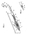
- illustrated therein is an example of application of the previously proposed actuator to the control of the lock of the hatchback door or rear boot of a motor vehicle.
- the actuator can be operated manually by means of a ring 100, which is connected via a ring 101 to the sheath 3 of a flexible-cable actuator device.
- a bushing 102 On the sheath 3 is secured a bushing 102, designed to bear upon a fixed detent 103 forming part of the structure 104 of the device of the lock of the hatch-back door.
- the co-operating action of the bushing 102 fixed to the sheath 3 and of the detent 103 prevents displacement of the sheath 3 in a direction opposite to that of actuation.
- a flexible cable 2 made of shape-memory material (of course, it is also possible to provide the device with a rigid cable instead of a flexible cable), which is secured at one end 2a to a cylindrical body 5, which is in turn connected, through a slit 105 made in the wall of the shell of the lock 104, to the controlled member of the lock (not illustrated).
- means of electrical supply (not illustrated) for applying an electrical pressure to the two opposite ends of the shape-memory cable 2 for the purpose of causing it to shorten.
- the sheath 3 remains stationary, since it cannot be displaced towards the left following upon the engagement of the bushing 102 against the fixed detent 103, whilst the shape-memory cable 2 is shortened, so causing a sliding of the cylinder 5 on the sheath 3 (so that the ring 11 moves away from the contrast surface 5a, overcoming the action of a spring 200) and again an actuation of the controlled member.
- the advantage of using the sheath of the actuator device as element of mechanical transmission in the case of manual actuation consists in the fact that in this way it is always possible to guarantee operation of the device even in the case of accidental failure of the flexible shape-memory cable.
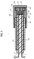
- a spacing layer 106 made of synthetic material that is joined to the sheath 3 and is fixed thereto.
- Said layer has only a spacing function, so that during operation of the device, there is created a relative movement of the flexible cable with respect thereto.
- a coating layer 110 which adheres to the shape-memory cable 2 and is chosen from an elastomer-silicone material or synthetic material such as to favour both cooling of the cable 2 after passage of the current has ceased and return of the cable 2 into its resting configuration as a result of the elastic return of the coating 110.
- the coating 110 which is adherent to the cable 2, performs the function of a spring distributed longitudinally, which is subject to compression when the cable 2 is shortened following upon its activation and consequently favours return of the cable into the resting position on account of its elastic return.
- the configuration of the shape-memory cable can be any whatsoever. It is moreover possible to extrude a number of shape-memory cables within the same coating, arranged parallel to one another. Likewise possible is a U-shaped cable configuration, with an ascending branch and a descending branch, and the two ends of the cable adjacent to one another, which, among other things, enables the advantage of a convenient electrical connection of the cable to the electrical-supply means.
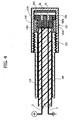
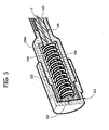
- FIGs 3 and 4 the parts in common to the ones of Figures 1 and 2 are designated with the same reference numbers.
- Said Figures illustrate, at an enlarged scale, the detail of the actuator adjacent to the end 2a of the shape-memory cable.
- two shape-memory wires 2 arranged parallel to one another, embedded in an elasto-silicone sheath 110 and having the respective ends 2a secured to two metal bodies 202a, 202b, the ends of which surface from a bushing of electrically insulating material 300, in which the metal bodies 202a, 202b are embedded.
- the insulating bushing 300 has an end flange 300a.
- the elasto-silicone sheath may be displaced within a tubular metal guide 106 that has an end surface 106a.
- Set axially between the end surface 106a and the flange 300a of the insulating bushing 300 is a compliant safety element 210 preferably in the form of a helical spring.
- the ends of the two wires 2 that are remote from the ends 2a are respectively connected to the two ends of the electrical-supply circuit.
- the circuit closes through the contact of the two contact elements 202a, 202b with a contact element 220 carried by the bottom wall of a cup-like element 221, which is secured in an axially adjustable position (by means of a threaded or knurled coupling 222) to the metal guide 106.
- the possibility of adjusting the axial position of the cup-like element 221 with respect to the metal guide 106 enables the load of the safety element 210 to be adjusted accordingly.
- the cup-like element 221 is operatively connected to the controlled
- the elastic element 210 yields, so that the contacts 202a, 202b displace towards the left ( Figure 4), without transmitting a corresponding movement to the cup-like element 221. Said relative movement causes a moving away of the two contact elements 202a, 202b from the contact element 220 with the consequent interruption of the electrical supply.
- Figure 5 shows a variant, which envisages a single shape-memory wire 2.
- the single wire 2 has a metallic end 202 fixed to its end, which is in electrical contact with the bottom part of the element 221.
- the electric current traverses the wire 2 up to the end 202, and thence passes through the element 221 and the body of the sheath 106, which is metallic, to return to the other end of electrical supply.
- a sheath 106 made of synthetic material, but provided with a metal path for closing the electrical circuit. The same applies to the cup-like element 221.
- An insulating bushing 400 is radially set between the spring 210 and the metal end 202 (set therein) and the sheath 106 (set on the outside).
Landscapes
- Engineering & Computer Science (AREA)
- General Engineering & Computer Science (AREA)
- Chemical & Material Sciences (AREA)
- Combustion & Propulsion (AREA)
- Mechanical Engineering (AREA)
- Oral & Maxillofacial Surgery (AREA)
- Health & Medical Sciences (AREA)
- Details Of Connecting Devices For Male And Female Coupling (AREA)
- Emergency Protection Circuit Devices (AREA)
- Electric Cable Arrangement Between Relatively Moving Parts (AREA)
- Prostheses (AREA)
- Manipulator (AREA)
- Details Of Aerials (AREA)
- Micromachines (AREA)
- Power-Operated Mechanisms For Wings (AREA)
Claims (11)
- Betätigungseinrichtung, umfassend ein gestrecktes Element (2) in der Form eines Kabels oder einer Stange, aufweisend ein Ende (2a), verbunden mit einem gesteuerten Bauteil, in welcher:- zumindest ein Abschnitt des gestreckten Elements (2) aus einem Formgedächtnismaterial aufgebaut ist, welches eine Formveränderung aufgrund Erwärmung durchmachen kann, zu dem Zweck, das gesteuerte Bauteil zu steuern; und- ein elektrischer Versorgungsschaltkreis vorhanden ist, um das gestreckte Element (2) dazu zu bringen, von einem elektrischen Strom durchquert zu werden, um seine Wärme zu übertragen,wobei die Einrichtung dadurch gekennzeichnet ist, dass sie Sensormittel (210) umfasst zum Erfassen eines Überschreitens eines vorher festgelegten Schwellenwertes der axialen Last, die auf das Formgedächtniselement (2) während seiner Aktivierung aufgebracht wird.
- Betätigungseinrichtung nach Anspruch 1, dadurch gekennzeichnet, dass die Sensormittel ein axial nachgiebiges Element (210) umfassen, wirksam zwischen das Ende (2a) des gestreckten Elements und das gesteuerte Bauteil gesetzt, wobei das nachgiebige Element (210) gestaltet ist, um beim Überschreiten des Schwellenwerts der axialen Last axial nachzugeben, so dass die Bewegung des Endes (2a) des gestreckten Elements (2) nicht auf das gesteuerte Bauteil übertragen wird, wenn die darauf aufgebrachte Last den vorher festgelegten Schwellenwert überschreitet.
- Betätigungseinrichtung nach Anspruch 2, dadurch gekennzeichnet, dass das nachgiebige Element (210) eine Feder ist.
- Betätigungseinrichtung nach Anspruch 3, dadurch gekennzeichnet, dass das nachgiebige Element (210) eine Schraubenfeder ist, die axial zwischen einen ersten Körper (202), verbunden mit dem Ende (2a) des Formgedächtniselements, und einen zweiten Körper (106), wirksam verbunden mit dem gesteuerten Bauteil, gesetzt ist.
- Betätigungseinrichtung nach irgendeinem der Ansprüche 2-4, dadurch gekennzeichnet, dass sie darüber hinaus Mittel zum Unterbrechen der elektrischen Versorgung des Formgedächtniselements (2) umfasst, wenn die Sensormittel (210) ein Überschreiten des Schwellenwertes der axialen Last auf das Formgedächtniselement wahrnehmen.
- Betätigungseinrichtung nach Anspruch 5, dadurch gekennzeichnet, dass die Mittel zum Unterbrechen der elektrischen Versorgung einen elektrischen Kontakt umfassen, der in den Versorgungsschaltkreis eingesetzt ist und aus zwei Kontaktelementen (202; 202a, 202b; 220) besteht, welche sich voneinander weg bewegen, wenn das nachgiebige Element (210) bei Überschreiten des vorher beschriebenen Schwellenwertes der axialen Last nachgibt.
- Betätigungseinrichtung nach Anspruch 6, dadurch gekennzeichnet, dass ein erstes Kontaktelement des elektrischen Kontakts aus einem ersten Körper (202; 202a; 202b) besteht, verbunden mit dem Ende (2a) des Formgedächtniselements (2), wobei das zweite Kontaktelement (220) durch einen zweiten Körper (221) getragen wird, wirksam verbunden mit dem gesteuerten Bauteil, so dass beim Nachgeben des nachgiebigen Elements (210) während der Aktivierung des Formgedächtniselements (2) der erste Körper in Bezug zu dem zweiten Körper versetzt wird, was zu einem Unterbrechen des elektrischen Kontakts führt.
- Betätigungseinrichtung nach Anspruch 7, dadurch gekennzeichnet, dass das Formgedächtniselement (2) innerhalb einer röhrenförmigen Führung (106) mit einer Endoberfläche (106a) gesetzt ist und dass das nachgiebige Element (210) wirksam zwischen die Endoberfläche (106a) der röhrenförmigen Führung (106) gesetzt ist.
- Betätigungseinrichtung nach Anspruch 8, dadurch gekennzeichnet, dass das zweite Kontaktelement (220) durch eine Bodenwand getragen wird, die dem ersten Kontaktelement (220) zugewandt ist und einen Teil eines Bauteils (221) bildet, welches mit der röhrenförmigen Führung (106) in einer einstellbaren Position verbunden ist.
- Betätigungseinrichtung nach Anspruch 3, dadurch gekennzeichnet, dass voraussehende Mittel (222) vorhanden sind zur Regulation der Last auf die Feder (210).
- Betätigungseinrichtung nach irgendeinem der vorherigen Ansprüche, dadurch gekennzeichnet, dass das gestreckte Formgedächtniselement einen oder mehrere Formgedächtnisdrähte (2) umfasst, welche parallel angeordnet sind.
Priority Applications (6)
| Application Number | Priority Date | Filing Date | Title |
|---|---|---|---|
| DE602004006146T DE602004006146T2 (de) | 2004-12-30 | 2004-12-30 | Formgedächtnisbetätigungseinrichtung mit Überspannungsschädensschutz |
| AT04425963T ATE360761T1 (de) | 2004-12-30 | 2004-12-30 | Formgedächtnisbetätigungseinrichtung mit überspannungsschädensschutz |
| EP04425963A EP1677014B1 (de) | 2004-12-30 | 2004-12-30 | Formgedächtnisbetätigungseinrichtung mit Überspannungsschädensschutz |
| US11/294,570 US7764159B2 (en) | 2004-12-30 | 2005-12-06 | Shape-memory actuator device with protection against over-stresses |
| JP2005361981A JP4612537B2 (ja) | 2004-12-30 | 2005-12-15 | 過剰応力に対する保護機能を備えた形状記憶アクチュエータデバイス |
| CNB200510003367XA CN100445581C (zh) | 2004-12-30 | 2005-12-30 | 具有对抗超应力的保护的形状记忆促动装置 |
Applications Claiming Priority (1)
| Application Number | Priority Date | Filing Date | Title |
|---|---|---|---|
| EP04425963A EP1677014B1 (de) | 2004-12-30 | 2004-12-30 | Formgedächtnisbetätigungseinrichtung mit Überspannungsschädensschutz |
Publications (2)
| Publication Number | Publication Date |
|---|---|
| EP1677014A1 EP1677014A1 (de) | 2006-07-05 |
| EP1677014B1 true EP1677014B1 (de) | 2007-04-25 |
Family
ID=34932971
Family Applications (1)
| Application Number | Title | Priority Date | Filing Date |
|---|---|---|---|
| EP04425963A Expired - Lifetime EP1677014B1 (de) | 2004-12-30 | 2004-12-30 | Formgedächtnisbetätigungseinrichtung mit Überspannungsschädensschutz |
Country Status (6)
| Country | Link |
|---|---|
| US (1) | US7764159B2 (de) |
| EP (1) | EP1677014B1 (de) |
| JP (1) | JP4612537B2 (de) |
| CN (1) | CN100445581C (de) |
| AT (1) | ATE360761T1 (de) |
| DE (1) | DE602004006146T2 (de) |
Families Citing this family (26)
| Publication number | Priority date | Publication date | Assignee | Title |
|---|---|---|---|---|
| BRPI0715879A2 (pt) * | 2006-08-17 | 2013-08-13 | Koninkl Philips Electronics Nv | atuador de pressço, roupa e/ou vestimenta, mÉtodo para aplicar pressço sobre um corpo humano ou animal, uso do material de memària de forma, e, produto de programa de computador |
| ITMI20071283A1 (it) * | 2007-06-27 | 2008-12-28 | Getters Spa | Attuatore comprendente elementi in lega a memoria di forma ad ampliato intervallo di temperature di utilizzo |
| EP2012029B1 (de) * | 2007-07-06 | 2009-11-11 | C.R.F. Società Consortile per Azioni | Dreh- und/oder Verschiebeverriegelungsvorrichtung eines Bolzens mit Formgedächtnisentriegelung |
| US8620878B2 (en) * | 2007-07-19 | 2013-12-31 | Ustream, Inc. | System and method of distributing multimedia content |
| EP2233739A1 (de) * | 2007-11-12 | 2010-09-29 | Konica Minolta Opto, Inc. | Formgedächtnislegierungsantriebsvorrichtung |
| US20110031924A1 (en) * | 2007-11-30 | 2011-02-10 | Konica Minolta Opto, Inc. | Shape memory alloy driver |
| WO2009069574A1 (ja) | 2007-11-30 | 2009-06-04 | Konica Minolta Opto, Inc. | 形状記憶合金駆動装置 |
| CN101910903B (zh) * | 2008-01-15 | 2013-08-07 | 柯尼卡美能达精密光学株式会社 | 形状记忆合金驱动装置 |
| JP2009299487A (ja) * | 2008-06-10 | 2009-12-24 | Olympus Corp | 形状記憶合金アクチュエータ |
| ATE481267T1 (de) | 2008-08-07 | 2010-10-15 | Fiat Ricerche | Ergonomische stützvorrichtung für den insassenkörper, für sessel oder sitze, insbesondere für kraftfahrzeugsitze |
| DE102009000957A1 (de) * | 2009-02-18 | 2010-10-07 | Hilti Aktiengesellschaft | Handgeführtes Eintreibgerät |
| US8844281B2 (en) * | 2011-02-28 | 2014-09-30 | GM Global Technology Operations LLC | Shape memory alloy heat engines and energy harvesting systems |
| US20150015001A1 (en) * | 2011-04-28 | 2015-01-15 | Electrolux Home Products Corporation N.V. | Electric Household Appliance Door Locking Device |
| DE102011111002A1 (de) * | 2011-08-18 | 2013-02-21 | B/E Aerospace Systems Gmbh | Aktuator |
| US8766564B2 (en) * | 2011-10-03 | 2014-07-01 | GM Global Technology Operations LLC | Method of reducing the effect of preheat time variation during shape memory alloy actuation |
| ITMI20121705A1 (it) * | 2012-10-10 | 2014-04-11 | Getters Spa | Interruttore elettrico bistabile con attuatore a memoria di forma |
| US20140225708A1 (en) * | 2013-02-14 | 2014-08-14 | GM Global Technology Operations LLC | Overload protection for shape memory alloy actuators |
| US10309136B2 (en) * | 2013-10-11 | 2019-06-04 | Illinois Tool Works Inc. | Locking and unlocking mechanism for a door lock |
| CA2939584C (en) * | 2014-02-26 | 2022-05-10 | Labinal, Llc | Circuit interruption device employing shape memory alloy element |
| US10221837B2 (en) * | 2014-05-13 | 2019-03-05 | Alfred R. Austen | Dynamic anti-buckling support for a long slender member with a high axial compression stress state and changing length |
| US10260958B2 (en) | 2015-04-22 | 2019-04-16 | GM Global Technology Operations LLC | Resettable sensor assembly and system |
| US10426267B2 (en) | 2016-09-09 | 2019-10-01 | Steelcase Inc. | Office systems with shape memory materials |
| DE102018009112B4 (de) * | 2018-11-20 | 2023-02-23 | Kunststoffverarbeitung Hoffmann Gmbh | Formgedächtnisaktor mit Schutzfunktion |
| US11585128B2 (en) | 2019-05-29 | 2023-02-21 | Faurecia Interior Systems, Inc. | Actuator for a vehicle compartment |
| US11541820B2 (en) * | 2020-03-30 | 2023-01-03 | Faurecia Interior Systems, Inc. | Actuator for a vehicle compartment |
| US11619076B2 (en) * | 2020-10-29 | 2023-04-04 | Inteva Products, Llc | Cable return assist assembly for vehicle latch mechanism |
Family Cites Families (14)
| Publication number | Priority date | Publication date | Assignee | Title |
|---|---|---|---|---|
| JP2000057917A (ja) * | 1998-08-07 | 2000-02-25 | Matsushita Electric Ind Co Ltd | サーマルプロテクタ |
| ITTO20010248A1 (it) * | 2001-03-16 | 2002-09-16 | Fiat Ricerche | Attuatore a memoria di forma, a funzionamento bistabile. |
| EP1245762B1 (de) * | 2001-03-27 | 2004-01-28 | C.R.F. Società Consortile per Azioni | Türschloss |
| ITTO20010362A1 (it) * | 2001-04-13 | 2002-10-13 | Fiat Ricerche | Proiettore per autoveicoli con mezzi di regolazione a memoria di forma. |
| ITTO20010618A1 (it) * | 2001-06-27 | 2002-12-27 | Fiat Ricerche | Dispositivo attuatore a cavo flessibile incorporante un elemento a memoria di forma. |
| EP1279784A1 (de) * | 2001-07-27 | 2003-01-29 | Oxford Automotive Italia di Gessaroli S.r.l. | Kraftfahrzeugsschloss, insbesondere für eine Heckklappe mit einem Formgedächtniselement |
| DE50214001D1 (de) * | 2002-02-27 | 2009-12-31 | Emz Hanauer Gmbh & Co Kgaa | Einheit mit Memory-Metall-Aktuator für Türverriegelungen von Haushaltsgeräten |
| ITTO20030045A1 (it) * | 2003-01-28 | 2004-07-29 | Fiat Ricerche | Dispositivo attuatore a cavo flessibile a memoria di forma |
| ITTO20030366A1 (it) * | 2003-05-20 | 2004-11-21 | Fiat Ricerche | Dispositivo di arresto con attuatore a memoria di forma. |
| DE602004001337T2 (de) * | 2004-05-03 | 2006-11-16 | C.R.F. S.C.P.A. | Bistabiler Schalter mit Formgedächtnismetall |
| DE602004002392T2 (de) * | 2004-05-21 | 2007-09-06 | C.R.F. Società Consortile per Azioni, Orbassano | Betätigungseinrichtung mit einem aus Formgedächtnismaterial bestehendem, flexiblem Kabel |
| ES2277231T3 (es) * | 2004-07-13 | 2007-07-01 | C.R.F. Societa Consortile Per Azioni | Aparato electrodomestico, en particular, maquina para lavar y/o secar un dispositivo de enclavamiento/liberacion de la puerta que se puede accionar electricamente. |
| EP1835097B1 (de) * | 2006-03-16 | 2008-09-03 | CRF Societa'Consortile per Azioni | Manuelle Betätigungsvorrichtung mit Formgedächtnishilfsantrieb |
| EP2012029B1 (de) * | 2007-07-06 | 2009-11-11 | C.R.F. Società Consortile per Azioni | Dreh- und/oder Verschiebeverriegelungsvorrichtung eines Bolzens mit Formgedächtnisentriegelung |
-
2004
- 2004-12-30 EP EP04425963A patent/EP1677014B1/de not_active Expired - Lifetime
- 2004-12-30 DE DE602004006146T patent/DE602004006146T2/de not_active Expired - Lifetime
- 2004-12-30 AT AT04425963T patent/ATE360761T1/de not_active IP Right Cessation
-
2005
- 2005-12-06 US US11/294,570 patent/US7764159B2/en active Active
- 2005-12-15 JP JP2005361981A patent/JP4612537B2/ja not_active Expired - Lifetime
- 2005-12-30 CN CNB200510003367XA patent/CN100445581C/zh not_active Expired - Lifetime
Non-Patent Citations (1)
| Title |
|---|
| None * |
Also Published As
| Publication number | Publication date |
|---|---|
| JP4612537B2 (ja) | 2011-01-12 |
| EP1677014A1 (de) | 2006-07-05 |
| JP2006189045A (ja) | 2006-07-20 |
| US7764159B2 (en) | 2010-07-27 |
| DE602004006146T2 (de) | 2008-01-10 |
| US20060148296A1 (en) | 2006-07-06 |
| ATE360761T1 (de) | 2007-05-15 |
| DE602004006146D1 (de) | 2007-06-06 |
| CN1796807A (zh) | 2006-07-05 |
| CN100445581C (zh) | 2008-12-24 |
Similar Documents
| Publication | Publication Date | Title |
|---|---|---|
| US7764159B2 (en) | Shape-memory actuator device with protection against over-stresses | |
| CA2447925C (en) | An actuator device with shape-memory flexible cable | |
| EP1399793B1 (de) | Betätigungseinrichtung mit einem aus formgedächtnismaterial bestehendem, flexiblem kabel | |
| US7810852B2 (en) | Manual actuating system assisted by a shape-memory actuator | |
| US11479996B2 (en) | Locking device for a motor vehicle | |
| KR20050028311A (ko) | 형상기억 액츄에이터를 포함하는, 자동차 시트의구성요소를 위한 해제장치 | |
| US9841074B2 (en) | Actuator for a functional unit of a motor vehicle | |
| CN104485242A (zh) | 致动单元 | |
| KR101287889B1 (ko) | 자동차용 페달 장치 | |
| EP2082914B1 (de) | Tankeinfüllstutzen für ein Kraftfahrzeug mit einer Formspeicherungsaktuatorvorrichtung zur Entsperrung des Stutzens und einem mit der Aktuatorvorrichtung verbundenen Anschlusselement | |
| EP1598568B1 (de) | Betätigungseinrichtung mit einem aus Formgedächtnismaterial bestehendem, flexiblem Kabel | |
| KR20150042749A (ko) | 액츄에이터 장치를 모니터링하는 방법 및 장치 | |
| CN112292497A (zh) | 锁闭系统和用于操作锁闭系统的方法 | |
| KR102926328B1 (ko) | 직류 전기 회로 차단 스위치 어셈블리 | |
| EP1726467A1 (de) | Sonnenblende-Einheit für Kraftfahrzeuge mit ein Memory-Shape Aktuator | |
| JP6632437B2 (ja) | パイロアクチュエータ | |
| EP3635765B1 (de) | Verbesserter thermomagnetischer aktuator in einem elektrischen sicherheitsschalter |
Legal Events
| Date | Code | Title | Description |
|---|---|---|---|
| PUAI | Public reference made under article 153(3) epc to a published international application that has entered the european phase |
Free format text: ORIGINAL CODE: 0009012 |
|
| 17P | Request for examination filed |
Effective date: 20050905 |
|
| AK | Designated contracting states |
Kind code of ref document: A1 Designated state(s): AT BE BG CH CY CZ DE DK EE ES FI FR GB GR HU IE IS IT LI LT LU MC NL PL PT RO SE SI SK TR |
|
| AX | Request for extension of the european patent |
Extension state: AL BA HR LV MK YU |
|
| GRAP | Despatch of communication of intention to grant a patent |
Free format text: ORIGINAL CODE: EPIDOSNIGR1 |
|
| GRAS | Grant fee paid |
Free format text: ORIGINAL CODE: EPIDOSNIGR3 |
|
| AKX | Designation fees paid |
Designated state(s): AT BE BG CH CY CZ DE DK EE ES FI FR GB GR HU IE IS IT LI LT LU MC NL PL PT RO SE SI SK TR |
|
| GRAA | (expected) grant |
Free format text: ORIGINAL CODE: 0009210 |
|
| AK | Designated contracting states |
Kind code of ref document: B1 Designated state(s): AT BE BG CH CY CZ DE DK EE ES FI FR GB GR HU IE IS IT LI LT LU MC NL PL PT RO SE SI SK TR |
|
| PG25 | Lapsed in a contracting state [announced via postgrant information from national office to epo] |
Ref country code: FI Free format text: LAPSE BECAUSE OF FAILURE TO SUBMIT A TRANSLATION OF THE DESCRIPTION OR TO PAY THE FEE WITHIN THE PRESCRIBED TIME-LIMIT Effective date: 20070425 Ref country code: LI Free format text: LAPSE BECAUSE OF FAILURE TO SUBMIT A TRANSLATION OF THE DESCRIPTION OR TO PAY THE FEE WITHIN THE PRESCRIBED TIME-LIMIT Effective date: 20070425 Ref country code: CH Free format text: LAPSE BECAUSE OF FAILURE TO SUBMIT A TRANSLATION OF THE DESCRIPTION OR TO PAY THE FEE WITHIN THE PRESCRIBED TIME-LIMIT Effective date: 20070425 |
|
| REG | Reference to a national code |
Ref country code: GB Ref legal event code: FG4D |
|
| REG | Reference to a national code |
Ref country code: SE Ref legal event code: TRGR |
|
| REG | Reference to a national code |
Ref country code: IE Ref legal event code: FG4D |
|
| REG | Reference to a national code |
Ref country code: CH Ref legal event code: EP |
|
| REF | Corresponds to: |
Ref document number: 602004006146 Country of ref document: DE Date of ref document: 20070606 Kind code of ref document: P |
|
| PG25 | Lapsed in a contracting state [announced via postgrant information from national office to epo] |
Ref country code: ES Free format text: LAPSE BECAUSE OF FAILURE TO SUBMIT A TRANSLATION OF THE DESCRIPTION OR TO PAY THE FEE WITHIN THE PRESCRIBED TIME-LIMIT Effective date: 20070805 |
|
| PG25 | Lapsed in a contracting state [announced via postgrant information from national office to epo] |
Ref country code: IS Free format text: LAPSE BECAUSE OF FAILURE TO SUBMIT A TRANSLATION OF THE DESCRIPTION OR TO PAY THE FEE WITHIN THE PRESCRIBED TIME-LIMIT Effective date: 20070825 |
|
| PG25 | Lapsed in a contracting state [announced via postgrant information from national office to epo] |
Ref country code: PT Free format text: LAPSE BECAUSE OF FAILURE TO SUBMIT A TRANSLATION OF THE DESCRIPTION OR TO PAY THE FEE WITHIN THE PRESCRIBED TIME-LIMIT Effective date: 20070925 |
|
| ET | Fr: translation filed | ||
| REG | Reference to a national code |
Ref country code: CH Ref legal event code: PL |
|
| NLV1 | Nl: lapsed or annulled due to failure to fulfill the requirements of art. 29p and 29m of the patents act | ||
| PG25 | Lapsed in a contracting state [announced via postgrant information from national office to epo] |
Ref country code: AT Free format text: LAPSE BECAUSE OF FAILURE TO SUBMIT A TRANSLATION OF THE DESCRIPTION OR TO PAY THE FEE WITHIN THE PRESCRIBED TIME-LIMIT Effective date: 20070425 Ref country code: PL Free format text: LAPSE BECAUSE OF FAILURE TO SUBMIT A TRANSLATION OF THE DESCRIPTION OR TO PAY THE FEE WITHIN THE PRESCRIBED TIME-LIMIT Effective date: 20070425 |
|
| PG25 | Lapsed in a contracting state [announced via postgrant information from national office to epo] |
Ref country code: BE Free format text: LAPSE BECAUSE OF FAILURE TO SUBMIT A TRANSLATION OF THE DESCRIPTION OR TO PAY THE FEE WITHIN THE PRESCRIBED TIME-LIMIT Effective date: 20070425 |
|
| PG25 | Lapsed in a contracting state [announced via postgrant information from national office to epo] |
Ref country code: BG Free format text: LAPSE BECAUSE OF FAILURE TO SUBMIT A TRANSLATION OF THE DESCRIPTION OR TO PAY THE FEE WITHIN THE PRESCRIBED TIME-LIMIT Effective date: 20070725 Ref country code: SI Free format text: LAPSE BECAUSE OF FAILURE TO SUBMIT A TRANSLATION OF THE DESCRIPTION OR TO PAY THE FEE WITHIN THE PRESCRIBED TIME-LIMIT Effective date: 20070425 Ref country code: NL Free format text: LAPSE BECAUSE OF FAILURE TO SUBMIT A TRANSLATION OF THE DESCRIPTION OR TO PAY THE FEE WITHIN THE PRESCRIBED TIME-LIMIT Effective date: 20070425 Ref country code: CZ Free format text: LAPSE BECAUSE OF FAILURE TO SUBMIT A TRANSLATION OF THE DESCRIPTION OR TO PAY THE FEE WITHIN THE PRESCRIBED TIME-LIMIT Effective date: 20070425 Ref country code: DK Free format text: LAPSE BECAUSE OF FAILURE TO SUBMIT A TRANSLATION OF THE DESCRIPTION OR TO PAY THE FEE WITHIN THE PRESCRIBED TIME-LIMIT Effective date: 20070425 |
|
| PG25 | Lapsed in a contracting state [announced via postgrant information from national office to epo] |
Ref country code: LT Free format text: LAPSE BECAUSE OF FAILURE TO SUBMIT A TRANSLATION OF THE DESCRIPTION OR TO PAY THE FEE WITHIN THE PRESCRIBED TIME-LIMIT Effective date: 20070425 Ref country code: SK Free format text: LAPSE BECAUSE OF FAILURE TO SUBMIT A TRANSLATION OF THE DESCRIPTION OR TO PAY THE FEE WITHIN THE PRESCRIBED TIME-LIMIT Effective date: 20070425 |
|
| PLBE | No opposition filed within time limit |
Free format text: ORIGINAL CODE: 0009261 |
|
| STAA | Information on the status of an ep patent application or granted ep patent |
Free format text: STATUS: NO OPPOSITION FILED WITHIN TIME LIMIT |
|
| 26N | No opposition filed |
Effective date: 20080128 |
|
| PG25 | Lapsed in a contracting state [announced via postgrant information from national office to epo] |
Ref country code: GR Free format text: LAPSE BECAUSE OF FAILURE TO SUBMIT A TRANSLATION OF THE DESCRIPTION OR TO PAY THE FEE WITHIN THE PRESCRIBED TIME-LIMIT Effective date: 20070726 |
|
| PG25 | Lapsed in a contracting state [announced via postgrant information from national office to epo] |
Ref country code: RO Free format text: LAPSE BECAUSE OF FAILURE TO SUBMIT A TRANSLATION OF THE DESCRIPTION OR TO PAY THE FEE WITHIN THE PRESCRIBED TIME-LIMIT Effective date: 20070425 |
|
| PG25 | Lapsed in a contracting state [announced via postgrant information from national office to epo] |
Ref country code: MC Free format text: LAPSE BECAUSE OF NON-PAYMENT OF DUE FEES Effective date: 20071231 |
|
| EUG | Se: european patent has lapsed | ||
| PG25 | Lapsed in a contracting state [announced via postgrant information from national office to epo] |
Ref country code: IE Free format text: LAPSE BECAUSE OF NON-PAYMENT OF DUE FEES Effective date: 20071231 Ref country code: SE Free format text: LAPSE BECAUSE OF NON-PAYMENT OF DUE FEES Effective date: 20071231 |
|
| PG25 | Lapsed in a contracting state [announced via postgrant information from national office to epo] |
Ref country code: EE Free format text: LAPSE BECAUSE OF FAILURE TO SUBMIT A TRANSLATION OF THE DESCRIPTION OR TO PAY THE FEE WITHIN THE PRESCRIBED TIME-LIMIT Effective date: 20070425 |
|
| PG25 | Lapsed in a contracting state [announced via postgrant information from national office to epo] |
Ref country code: CY Free format text: LAPSE BECAUSE OF FAILURE TO SUBMIT A TRANSLATION OF THE DESCRIPTION OR TO PAY THE FEE WITHIN THE PRESCRIBED TIME-LIMIT Effective date: 20070425 |
|
| GBPC | Gb: european patent ceased through non-payment of renewal fee |
Effective date: 20081230 |
|
| PG25 | Lapsed in a contracting state [announced via postgrant information from national office to epo] |
Ref country code: LU Free format text: LAPSE BECAUSE OF NON-PAYMENT OF DUE FEES Effective date: 20071230 |
|
| PG25 | Lapsed in a contracting state [announced via postgrant information from national office to epo] |
Ref country code: HU Free format text: LAPSE BECAUSE OF FAILURE TO SUBMIT A TRANSLATION OF THE DESCRIPTION OR TO PAY THE FEE WITHIN THE PRESCRIBED TIME-LIMIT Effective date: 20071026 Ref country code: TR Free format text: LAPSE BECAUSE OF FAILURE TO SUBMIT A TRANSLATION OF THE DESCRIPTION OR TO PAY THE FEE WITHIN THE PRESCRIBED TIME-LIMIT Effective date: 20070425 |
|
| PG25 | Lapsed in a contracting state [announced via postgrant information from national office to epo] |
Ref country code: GB Free format text: LAPSE BECAUSE OF NON-PAYMENT OF DUE FEES Effective date: 20081230 |
|
| REG | Reference to a national code |
Ref country code: FR Ref legal event code: PLFP Year of fee payment: 12 |
|
| REG | Reference to a national code |
Ref country code: FR Ref legal event code: PLFP Year of fee payment: 13 |
|
| REG | Reference to a national code |
Ref country code: FR Ref legal event code: PLFP Year of fee payment: 14 |
|
| PGFP | Annual fee paid to national office [announced via postgrant information from national office to epo] |
Ref country code: FR Payment date: 20231122 Year of fee payment: 20 Ref country code: DE Payment date: 20231121 Year of fee payment: 20 |
|
| REG | Reference to a national code |
Ref country code: DE Ref legal event code: R071 Ref document number: 602004006146 Country of ref document: DE |
|
| PGFP | Annual fee paid to national office [announced via postgrant information from national office to epo] |
Ref country code: IT Payment date: 20231121 Year of fee payment: 20 |