EP1677015B1 - Structure de bielle de torsion - Google Patents
Structure de bielle de torsion Download PDFInfo
- Publication number
- EP1677015B1 EP1677015B1 EP04791959.2A EP04791959A EP1677015B1 EP 1677015 B1 EP1677015 B1 EP 1677015B1 EP 04791959 A EP04791959 A EP 04791959A EP 1677015 B1 EP1677015 B1 EP 1677015B1
- Authority
- EP
- European Patent Office
- Prior art keywords
- cross
- rod
- torque rod
- shape
- torque
- Prior art date
- Legal status (The legal status is an assumption and is not a legal conclusion. Google has not performed a legal analysis and makes no representation as to the accuracy of the status listed.)
- Expired - Lifetime
Links
- 241001247986 Calotropis procera Species 0.000 claims description 10
- 239000011800 void material Substances 0.000 claims description 9
- 241000264877 Hippospongia communis Species 0.000 claims 1
- 238000005452 bending Methods 0.000 description 10
- 238000010276 construction Methods 0.000 description 6
- 239000011347 resin Substances 0.000 description 5
- 229920005989 resin Polymers 0.000 description 5
- XEEYBQQBJWHFJM-UHFFFAOYSA-N Iron Chemical compound [Fe] XEEYBQQBJWHFJM-UHFFFAOYSA-N 0.000 description 4
- 239000004952 Polyamide Substances 0.000 description 3
- 229910052782 aluminium Inorganic materials 0.000 description 3
- XAGFODPZIPBFFR-UHFFFAOYSA-N aluminium Chemical compound [Al] XAGFODPZIPBFFR-UHFFFAOYSA-N 0.000 description 3
- 230000006835 compression Effects 0.000 description 3
- 238000007906 compression Methods 0.000 description 3
- 229910052751 metal Inorganic materials 0.000 description 3
- 239000002184 metal Substances 0.000 description 3
- 238000000034 method Methods 0.000 description 3
- 229920002647 polyamide Polymers 0.000 description 3
- 238000010586 diagram Methods 0.000 description 2
- 238000003672 processing method Methods 0.000 description 2
- 229910000838 Al alloy Inorganic materials 0.000 description 1
- 229910001018 Cast iron Inorganic materials 0.000 description 1
- 229910000640 Fe alloy Inorganic materials 0.000 description 1
- 238000005266 casting Methods 0.000 description 1
- 230000000694 effects Effects 0.000 description 1
- 229920006351 engineering plastic Polymers 0.000 description 1
- 230000003116 impacting effect Effects 0.000 description 1
- 229910052742 iron Inorganic materials 0.000 description 1
- 239000000463 material Substances 0.000 description 1
- 150000002739 metals Chemical class 0.000 description 1
- 229920006122 polyamide resin Polymers 0.000 description 1
- 230000001105 regulatory effect Effects 0.000 description 1
- 230000008719 thickening Effects 0.000 description 1
Images


Classifications
-
- B—PERFORMING OPERATIONS; TRANSPORTING
- B60—VEHICLES IN GENERAL
- B60G—VEHICLE SUSPENSION ARRANGEMENTS
- B60G7/00—Pivoted suspension arms; Accessories thereof
- B60G7/001—Suspension arms, e.g. constructional features
-
- B—PERFORMING OPERATIONS; TRANSPORTING
- B60—VEHICLES IN GENERAL
- B60K—ARRANGEMENT OR MOUNTING OF PROPULSION UNITS OR OF TRANSMISSIONS IN VEHICLES; ARRANGEMENT OR MOUNTING OF PLURAL DIVERSE PRIME-MOVERS IN VEHICLES; AUXILIARY DRIVES FOR VEHICLES; INSTRUMENTATION OR DASHBOARDS FOR VEHICLES; ARRANGEMENTS IN CONNECTION WITH COOLING, AIR INTAKE, GAS EXHAUST OR FUEL SUPPLY OF PROPULSION UNITS IN VEHICLES
- B60K5/00—Arrangement or mounting of internal-combustion or jet-propulsion units
- B60K5/12—Arrangement of engine supports
- B60K5/1241—Link-type support
-
- F—MECHANICAL ENGINEERING; LIGHTING; HEATING; WEAPONS; BLASTING
- F16—ENGINEERING ELEMENTS AND UNITS; GENERAL MEASURES FOR PRODUCING AND MAINTAINING EFFECTIVE FUNCTIONING OF MACHINES OR INSTALLATIONS; THERMAL INSULATION IN GENERAL
- F16C—SHAFTS; FLEXIBLE SHAFTS; ELEMENTS OR CRANKSHAFT MECHANISMS; ROTARY BODIES OTHER THAN GEARING ELEMENTS; BEARINGS
- F16C7/00—Connecting-rods or like links pivoted at both ends; Construction of connecting-rod heads
- F16C7/04—Connecting-rods or like links pivoted at both ends; Construction of connecting-rod heads with elastic intermediate part of fluid cushion
-
- F—MECHANICAL ENGINEERING; LIGHTING; HEATING; WEAPONS; BLASTING
- F16—ENGINEERING ELEMENTS AND UNITS; GENERAL MEASURES FOR PRODUCING AND MAINTAINING EFFECTIVE FUNCTIONING OF MACHINES OR INSTALLATIONS; THERMAL INSULATION IN GENERAL
- F16F—SPRINGS; SHOCK-ABSORBERS; MEANS FOR DAMPING VIBRATION
- F16F1/00—Springs
- F16F1/36—Springs made of rubber or other material having high internal friction, e.g. thermoplastic elastomers
- F16F1/38—Springs made of rubber or other material having high internal friction, e.g. thermoplastic elastomers with a sleeve of elastic material between a rigid outer sleeve and a rigid inner sleeve or pin, i.e. bushing-type
- F16F1/3842—Method of assembly, production or treatment; Mounting thereof
- F16F1/3849—Mounting brackets therefor, e.g. stamped steel brackets; Restraining links
-
- B—PERFORMING OPERATIONS; TRANSPORTING
- B60—VEHICLES IN GENERAL
- B60G—VEHICLE SUSPENSION ARRANGEMENTS
- B60G2206/00—Indexing codes related to the manufacturing of suspensions: constructional features, the materials used, procedures or tools
- B60G2206/01—Constructional features of suspension elements, e.g. arms, dampers, springs
- B60G2206/10—Constructional features of arms
- B60G2206/11—Constructional features of arms the arm being a radius or track or torque or steering rod or stabiliser end link
-
- B—PERFORMING OPERATIONS; TRANSPORTING
- B60—VEHICLES IN GENERAL
- B60G—VEHICLE SUSPENSION ARRANGEMENTS
- B60G2206/00—Indexing codes related to the manufacturing of suspensions: constructional features, the materials used, procedures or tools
- B60G2206/01—Constructional features of suspension elements, e.g. arms, dampers, springs
- B60G2206/70—Materials used in suspensions
- B60G2206/71—Light weight materials
- B60G2206/7104—Thermoplastics
-
- F—MECHANICAL ENGINEERING; LIGHTING; HEATING; WEAPONS; BLASTING
- F16—ENGINEERING ELEMENTS AND UNITS; GENERAL MEASURES FOR PRODUCING AND MAINTAINING EFFECTIVE FUNCTIONING OF MACHINES OR INSTALLATIONS; THERMAL INSULATION IN GENERAL
- F16C—SHAFTS; FLEXIBLE SHAFTS; ELEMENTS OR CRANKSHAFT MECHANISMS; ROTARY BODIES OTHER THAN GEARING ELEMENTS; BEARINGS
- F16C2326/00—Articles relating to transporting
- F16C2326/01—Parts of vehicles in general
- F16C2326/05—Vehicle suspensions, e.g. bearings, pivots or connecting rods used therein
-
- Y—GENERAL TAGGING OF NEW TECHNOLOGICAL DEVELOPMENTS; GENERAL TAGGING OF CROSS-SECTIONAL TECHNOLOGIES SPANNING OVER SEVERAL SECTIONS OF THE IPC; TECHNICAL SUBJECTS COVERED BY FORMER USPC CROSS-REFERENCE ART COLLECTIONS [XRACs] AND DIGESTS
- Y10—TECHNICAL SUBJECTS COVERED BY FORMER USPC
- Y10T—TECHNICAL SUBJECTS COVERED BY FORMER US CLASSIFICATION
- Y10T74/00—Machine element or mechanism
- Y10T74/21—Elements
- Y10T74/2142—Pitmans and connecting rods
Definitions
- the present invention relates to a torque rod for arresting the movement of an engine of a motor vehicle, and related to improving torque rods made of resin or metal that connect a pair of rubber bushes or cylinders.
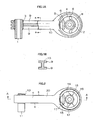
- a torque rod 10 connecting a pair of rubber bushes 3,4 and cylinders 1,2, is usually made of resin, iron or aluminum.
- the core of the rod portion is either a rectangular cross-sectional shape or H section cross section ribbed structure (see Figure 1B and the patent publication reference 1).
- 6 are hollow portions
- 5,8 are rubber stoppers
- 9 is a rib formed on the surface.
- Figure 1B is the cross section of Figure 1A at the line "a-a".
- WO 02/24394 discloses a torque rod structure comprising a rod portion, the cross-sectional shape of the central portion of the rod portion forming an approximately rectangular shape and one pair of opposing faces of the rectangular shape forming a shape which bulges outwards, such that the central cross-section of the of the rod portion is thicker than the ends thereof and wherein the rod portion is shaped with a plurality of void portions.
- the invention is made to solve the above problems, and addresses the requirements by providing an improved shape of the rod portion with increased stiffness to bending and twisting.
- a first aspect of the invention is a torque rod as set out in Claim 1.
- a second aspect of the invention is a torque rod as set out in Claim 8.
- the invention has a configuration which is one of the above torque rod structures, and in all of the configurations by adding the great improvement in the rod portion, not only does the torque rod have compression and tensional strength, but also significantly increased bending and twisting stiffness.
- Specific structures include a rod portion having plural void (honeycomb) structure (the first aspect), or having rib structure (the second aspect). By these structures, and further by preferably thickening the central cross-section, the twisting stiffness can be increased to 2 to 3 times that of a conventional ribbed shape.
- the torque rod of the invention is a torque rod which is made of resin or metal, for example cast iron or aluminum.
- the invention includes a rod portion formed with plural void portions (the first aspect of the invention), or with plural hole portions forming cross-shaped ribs (the third aspect of the invention), to improve the twisting and bending stiffness of the rod portion.
- a structure is included wherein the central cross-section of the rod portion is made thicker than the ends thereof, and the like.
- this can be, for example, made of metals, typically iron or aluminum alloys, or made of resins called engineering plastics, and amongst these polyamide is the most preferable applicable.
- the torque rod can be manufactured by a resin or aluminum casting method and at the same time, for example, a processing method such as a core method or AGI processing method can be used to form the hollow center.
- a processing method such as a core method or AGI processing method can be used to form the hollow center.
- the first aspect and second aspects are preferably used when, due to constraints in the mould release construction and the like, the torque rod cannot be one of a hollow construction, and have a construction which can be removed from the mould in one direction or both directions.
- This construction in order to increase the polar modulus of section, results in a rod portion in a comb shape or lattice shape (cross-shaped ribs). In these constructions too, of course, a bulging central portion of the rod is also used.
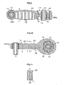
- Figures 2 to 6 are examples which are not according to the invention, Figure 2 is a front view, Figure 3 is a side view, Figure 4 is a cross-section on the line A-A, Figure 5 is a cross-section on the line B-B, Figure 6 is a cross-section on the line C-C.
- the numerals 11,12 are a pair of internal cylinders disposed at 90 degrees to each other, 13 is a rubber bush which covers the internal cylinder 11, 14 is a rubber bush which covers the internal cylinder 12, 15 is a hollow portion formed on the inner and outer sides of the internal cylinder 12, and stoppers 16,17 are provided sandwiched by the hollow portion 15.
- the torque rod 20 made of a polyamide resin is connected thereto.
- the torque rod 20 is approximately rectangular in cross-section on the line B-B, and the corresponding faces "a” and “b” are formed parallel. Faces “c” and “d” form a shape in which the central portion bulges, and the hollow portion 21 is inside this portion.
- Figures 7 to 11 are examples of the first aspect of the invention, Figure 7 is a front view, Figure 8 is a side view, Figure 9 is a cross-section on the line D-D, Figure 10 is a cross-section on the line E-E, and Figure 11 is a cross-section on the line F-F.
- the numerals 11 to 17 are the same as in the previous example and the explanation thereof will be omitted.
- the torque rod 20 made of polyamide is approximately rectangular in cross-section on the line B-B, and the corresponding faces "a" and “b” are formed parallel. Faces “c” and “d” form a shape in which the central portion bulges, and the on the face "c” two rows of void portions 22 are formed. 20a is a rib formed on the outer periphery of the torque rod 20.
- the bending stiffness and twisting stiffness each become about twice that of a conventional torque rod.
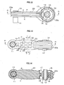
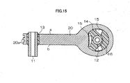
- Figures 12 to 17 are examples of the second aspect of the invention, Figure 12 is a front view, Figure 13 is a side view, Figure 14 is a cross-section on the line G-G, Figure 15 is a cross-section on the line H-H, Figure 16 is a cross-section on the line I-I, and Figure 17 is a cross-section on the line J-J.
- the numerals 11 to 17 are the same as in the previous examples and the explanation thereof will be omitted.
- the torque rod 20 made of polyamide is approximately rectangular in cross-section on the line B-B, and the corresponding faces "a” and “b” are formed parallel. Faces “c” and “d” form a shape in which the central portion bulges, and on the parallel faces “a” and “b” two rows of blind holes 23 are formed. Overall, cross-shaped ribs 24 are formed.
- the bending stiffness and twisting stiffness each become about 2:5 times that of a conventional torque rod.
- the bending stiffness and twisting stiffness can be greatly improved, and these rods are applicable not only in the field of torque rods for motor vehicles but in a great number of fields.
- the range of applicability is extremely wide.
Landscapes
- Engineering & Computer Science (AREA)
- General Engineering & Computer Science (AREA)
- Mechanical Engineering (AREA)
- Manufacturing & Machinery (AREA)
- Chemical & Material Sciences (AREA)
- Combustion & Propulsion (AREA)
- Transportation (AREA)
- Shafts, Cranks, Connecting Bars, And Related Bearings (AREA)
- Vehicle Body Suspensions (AREA)
- Vibration Prevention Devices (AREA)
- Springs (AREA)
Claims (8)
- Barre de torsion (20) destinée à arrêter le mouvement d'un moteur de véhicule automobile, la structure de barre de torsion comprenant une portion de barre comportant une paire de douilles en caoutchouc (13, 14) intégrées qui sont formées respectivement autour d'une paire de cylindres (11, 12), la portion de barre reliant les deux douilles en caoutchouc (13, 14),
la forme de la section transversale de la partie centrale de la portion de barre ayant un profil à peu près rectangulaire et une paire de faces opposées (c, d) du profil rectangulaire ayant une forme bombée vers l'extérieur, de sorte que la section transversale centrale de la portion de barre est plus épaisse que ses extrémités ;
la portion de barre présentant une pluralité de portions vides (22) ; et
les portions vides (22) étant formées sur les faces convexes (c, d). - Structure de barre de torsion (20) selon la revendication 1, des nervures cruciformes (24) étant formées sur la portion de barre.
- Structure de barre de torsion (20) selon la revendication 1, le profil de la section transversale au voisinage de la partie centrale présentant, le long de la direction longitudinale de la portion de barre, une série de sections transversales pourvues d'une portion entaillée qui alternent avec des sections transversales non pourvues d'une portion entaillée.
- Structure de barre de torsion (20) selon la revendication 3, les portions vides (22) correspondant aux portions entaillées.
- Structure de barre de torsion (20) selon la revendication 4, les portions vides se présentant sous la forme de deux rangées de trous borgnes.
- Structure de barre de torsion selon la revendication 3, les portions entaillées étant formées sur les faces convexes (c, d).
- Structure de barre de torsion selon la revendication 3, la barre ayant une forme en nid d'abeilles.
- Barre de torsion (20), la structure de barre de torsion comprenant une portion de barre comportant une paire de douilles en caoutchouc (13, 14) intégrées qui sont formées respectivement autour d'une paire de cylindres (11, 12), la portion de barre reliant les deux douilles en caoutchouc (13, 14),
la forme de la section transversale de la partie centrale de la portion de barre ayant un profil à peu près rectangulaire et une paire de faces opposées (c, d) du profil rectangulaire ayant une forme bombée vers l'extérieur, de sorte que la section transversale centrale de la portion de barre est plus épaisse que ses extrémités, et l'autre paire de faces opposées (a, b) du profil rectangulaire étant formée de manière à ce que ces faces soient parallèles ;
le profil de la section transversale au voisinage de la partie centrale présentant, le long de la direction longitudinale de la portion de barre, une série de sections transversales pourvues d'une portion entaillée qui alternent avec des sections transversales non pourvues d'une portion entaillée ;
les portions entaillées se présentant sous la forme de deux rangées de trous borgnes (23) sur les faces parallèles (a, b) du profil rectangulaire, les trous borgnes (23) formant des nervures cruciformes (24) sur la portion de barre.
Applications Claiming Priority (2)
| Application Number | Priority Date | Filing Date | Title |
|---|---|---|---|
| JP2003345741A JP4436103B2 (ja) | 2003-10-03 | 2003-10-03 | トルクロッド構造 |
| PCT/JP2004/014492 WO2005033529A1 (fr) | 2003-10-03 | 2004-10-01 | Structure de bielle de torsion |
Publications (3)
| Publication Number | Publication Date |
|---|---|
| EP1677015A1 EP1677015A1 (fr) | 2006-07-05 |
| EP1677015A4 EP1677015A4 (fr) | 2009-08-05 |
| EP1677015B1 true EP1677015B1 (fr) | 2015-08-12 |
Family
ID=34419468
Family Applications (1)
| Application Number | Title | Priority Date | Filing Date |
|---|---|---|---|
| EP04791959.2A Expired - Lifetime EP1677015B1 (fr) | 2003-10-03 | 2004-10-01 | Structure de bielle de torsion |
Country Status (4)
| Country | Link |
|---|---|
| US (1) | US20070272051A1 (fr) |
| EP (1) | EP1677015B1 (fr) |
| JP (1) | JP4436103B2 (fr) |
| WO (1) | WO2005033529A1 (fr) |
Families Citing this family (31)
| Publication number | Priority date | Publication date | Assignee | Title |
|---|---|---|---|---|
| JP4046094B2 (ja) * | 2004-03-19 | 2008-02-13 | 東海ゴム工業株式会社 | トルクロッド |
| KR100867626B1 (ko) | 2007-06-08 | 2008-11-10 | 현대자동차주식회사 | 차량용 롤로드 |
| DE102008013155A1 (de) * | 2008-03-07 | 2009-09-10 | Audi Ag | Verstellbarer Radträger |
| US8337113B2 (en) * | 2009-06-10 | 2012-12-25 | Radar Industries, Inc. | Stamped link for supporting an engine |
| JP5595702B2 (ja) * | 2009-09-25 | 2014-09-24 | 株式会社ブリヂストン | トルクロッド |
| FR2965867B1 (fr) * | 2010-10-12 | 2013-08-09 | Airbus Operations Sas | Bielle structurale adaptee a filtrer des vibrations longitudinales |
| JP2012097878A (ja) * | 2010-11-05 | 2012-05-24 | Kurashiki Kako Co Ltd | 防振連結ロッド |
| JP5913848B2 (ja) * | 2011-07-13 | 2016-04-27 | 日産自動車株式会社 | トルクロッド |
| CN104541088B (zh) * | 2012-08-11 | 2017-07-25 | 山下橡胶株式会社 | 防振装置 |
| JP5376184B2 (ja) * | 2012-10-09 | 2013-12-25 | トヨタ自動車株式会社 | 車両用i型サスペンションアーム |
| JP5985967B2 (ja) * | 2012-11-27 | 2016-09-06 | 山下ゴム株式会社 | トルクロッド |
| JP6088286B2 (ja) * | 2013-02-25 | 2017-03-01 | 株式会社ブリヂストン | 防振装置 |
| JP6068215B2 (ja) * | 2013-03-20 | 2017-01-25 | 東洋ゴム工業株式会社 | 防振装置 |
| EP3053761B1 (fr) * | 2013-10-02 | 2019-01-09 | Nhk Spring Co., Ltd. | Élément de bras de suspension |
| CN104132054B (zh) * | 2014-07-21 | 2018-03-06 | 湖州东鸥机械制造有限公司 | 用于柴油机传动系统的连杆 |
| EP2995481B1 (fr) * | 2014-09-12 | 2016-09-07 | Edai Technical Unit, A.I.E. | Procédé d'obtention d'un bras de suspensions à liaisons multiples de véhicules automobiles et bras de suspension |
| JP6431380B2 (ja) * | 2015-01-13 | 2018-11-28 | 株式会社ブリヂストン | 防振装置 |
| US9651136B2 (en) * | 2015-04-01 | 2017-05-16 | Borgwarner Inc. | Transfer case with aluminum yoke |
| JP6514974B2 (ja) * | 2015-07-03 | 2019-05-15 | 日立グローバルライフソリューションズ株式会社 | 固定部材を備えた機器 |
| GB2540579B (en) * | 2015-07-22 | 2020-03-18 | Ford Global Tech Llc | A component mount |
| JP2017032043A (ja) * | 2015-07-31 | 2017-02-09 | スズキ株式会社 | エンジンのコネクティングロッド |
| JP6570967B2 (ja) * | 2015-10-28 | 2019-09-04 | 株式会社ブリヂストン | トルクロッド |
| JP6855189B2 (ja) * | 2016-08-25 | 2021-04-07 | 株式会社ブリヂストン | トルクロッド |
| DE102016224023A1 (de) * | 2016-12-02 | 2018-06-07 | Ford Global Technologies, Llc | Querlenker für eine Radaufhängung eines Fahrzeugs und Verfahren zu dessen Herstellung |
| US10308102B2 (en) * | 2017-02-07 | 2019-06-04 | Vibracoustic Usa, Inc. | Damped torque roll restrictor |
| JP6824771B2 (ja) * | 2017-02-16 | 2021-02-03 | Toyo Tire株式会社 | トルクロッド及びその製造方法 |
| CN109760503B (zh) * | 2018-12-27 | 2020-07-10 | 东风汽车集团有限公司 | 动力总成抗扭拉杆结构 |
| DE102019202900A1 (de) * | 2019-03-04 | 2020-09-10 | Zf Friedrichshafen Ag | Koppelstange |
| DE102020212622A1 (de) * | 2020-10-06 | 2022-04-07 | Zf Friedrichshafen Ag | Mehrpunktlenker für ein Fahrwerk |
| JP2022146559A (ja) * | 2021-03-22 | 2022-10-05 | 本田技研工業株式会社 | トレーリングアーム |
| FR3146962B1 (fr) * | 2023-03-24 | 2025-03-14 | Conseil & Technique | Dispositif de bielle présentant des capacités d’amortissement |
Family Cites Families (15)
| Publication number | Priority date | Publication date | Assignee | Title |
|---|---|---|---|---|
| JPS58188712A (ja) * | 1982-04-30 | 1983-11-04 | Nissan Motor Co Ltd | 自動車用リンク及びその製造方法 |
| GB8500684D0 (en) * | 1985-01-11 | 1985-02-13 | Secretary Trade Ind Brit | Connecting road |
| JPH01126413A (ja) * | 1987-11-09 | 1989-05-18 | Tokai Rubber Ind Ltd | 樹脂製連結ロッドの製造方法 |
| GB9423196D0 (en) * | 1994-11-17 | 1995-01-04 | Carey Charles O B | A connecting rod |
| DE4441219C2 (de) * | 1994-11-19 | 2001-12-06 | Zf Lemfoerder Metallwaren Ag | Pendelstütze für das Einsetzen von die Lagerstellen bildenden Lagerhüben für die gelenkige Verbindung von Fahrwerksteilen in Kraftfahrzeugen |
| JPH11101286A (ja) * | 1997-09-29 | 1999-04-13 | Tokai Rubber Ind Ltd | ブッシュ装着用部材の製造方法 |
| JPH11218173A (ja) * | 1998-01-30 | 1999-08-10 | Tokai Rubber Ind Ltd | 防振懸架装置 |
| JP2000035029A (ja) * | 1998-07-16 | 2000-02-02 | Tokai Rubber Ind Ltd | ブッシュ装着部材 |
| JP4020529B2 (ja) * | 1999-03-24 | 2007-12-12 | 日野自動車株式会社 | トルクロッド |
| US6619533B1 (en) * | 2000-09-22 | 2003-09-16 | Tower Automotive Technology Products, Inc. | Multi-piece extruded link arm |
| JP2002166714A (ja) * | 2000-11-30 | 2002-06-11 | Suzuki Motor Corp | サスペンションアーム |
| JP2003002025A (ja) * | 2001-06-22 | 2003-01-08 | Suzuki Motor Corp | サスペンションアーム構造 |
| JP2003206991A (ja) * | 2002-01-10 | 2003-07-25 | Tokai Rubber Ind Ltd | 防振装置及びこれに用いる金具と防振装置の製造方法 |
| DE10206809A1 (de) * | 2002-02-19 | 2003-09-18 | Man Nutzfahrzeuge Ag | Vierpunktlenker zur Anbindung einer Starrachse an den Rahmen eines Nutzfahrzeuges |
| CN100465002C (zh) * | 2002-05-31 | 2009-03-04 | 麦格纳国际公司 | 液压成形的控制臂 |
-
2003
- 2003-10-03 JP JP2003345741A patent/JP4436103B2/ja not_active Expired - Lifetime
-
2004
- 2004-10-01 US US10/574,497 patent/US20070272051A1/en not_active Abandoned
- 2004-10-01 WO PCT/JP2004/014492 patent/WO2005033529A1/fr not_active Ceased
- 2004-10-01 EP EP04791959.2A patent/EP1677015B1/fr not_active Expired - Lifetime
Also Published As
| Publication number | Publication date |
|---|---|
| JP2005113952A (ja) | 2005-04-28 |
| EP1677015A4 (fr) | 2009-08-05 |
| WO2005033529A1 (fr) | 2005-04-14 |
| JP4436103B2 (ja) | 2010-03-24 |
| US20070272051A1 (en) | 2007-11-29 |
| EP1677015A1 (fr) | 2006-07-05 |
Similar Documents
| Publication | Publication Date | Title |
|---|---|---|
| EP1677015B1 (fr) | Structure de bielle de torsion | |
| CN108374830B (zh) | 具有定制刚度的轻质连杆 | |
| KR101216773B1 (ko) | 사점 현가 암 | |
| US11827341B2 (en) | Thin-skin side stay beams and landing gear assemblies | |
| US5885688A (en) | Steel reinforced filled polymer torque rod | |
| US6672654B2 (en) | Vehicle body frame hollow member | |
| KR101404982B1 (ko) | 크랭크샤프트의 제조 방법 | |
| JP2004538430A (ja) | 軽量クランクシャフト | |
| CN212290392U (zh) | 一种复合舱段结构及飞行器 | |
| DE102014220443B4 (de) | Lenker für die Anbindung eines Fahrzeugrads an ein Fahrzeug sowie Fahrzeugradaufhängung | |
| CN105436418A (zh) | 由高收缩金属合金制造曲柄轴的方法 | |
| DE102010051884A1 (de) | Verfahren zur Herstellung eines Querlenkers und Querlenker | |
| DE60100460T2 (de) | Elastische Vorrichtung zur Aufhängung einer schwingenden Struktur gegenüber einer steifen Struktur | |
| JPH11170935A (ja) | 構造部材 | |
| KR101792107B1 (ko) | 차량용 하이브리드 현가암 및 그 제조방법 | |
| EP2357097B1 (fr) | Bras de contrôle d'une barre de torsion et barre de torsion | |
| EP3250804A1 (fr) | Piston destiné à un moteur à combustion interne et procédé de fabrication dudit piston destiné à un moteur à combustion interne | |
| JP5926096B2 (ja) | トルクロッド | |
| US20070278828A1 (en) | Pillar for a Motor Vehicle | |
| JP3657474B2 (ja) | 内燃機関のクランク軸 | |
| CN117533415A (zh) | 后地板结构、铸造模具 | |
| CN214993084U (zh) | 内置钢筋笼的加劲钢管-高性能混凝土组合结构桥塔 | |
| CN220042113U (zh) | 一种预制结构梁、电池包下壳体及电池包 | |
| DE102019214089A1 (de) | Batteriemodulgehäuse für eine Fahrzeugbatterie, Fahrzeugbatterie und Fahrzeug | |
| EP3705742B1 (fr) | Bielle pour moteur à combustion interne et méthode de production de ladite bielle |
Legal Events
| Date | Code | Title | Description |
|---|---|---|---|
| PUAI | Public reference made under article 153(3) epc to a published international application that has entered the european phase |
Free format text: ORIGINAL CODE: 0009012 |
|
| 17P | Request for examination filed |
Effective date: 20060413 |
|
| AK | Designated contracting states |
Kind code of ref document: A1 Designated state(s): DE FR IT |
|
| DAX | Request for extension of the european patent (deleted) | ||
| RBV | Designated contracting states (corrected) |
Designated state(s): DE FR IT |
|
| RAP1 | Party data changed (applicant data changed or rights of an application transferred) |
Owner name: BRIDGESTONE CORPORATION Owner name: HONDA MOTOR CO., LTD. |
|
| A4 | Supplementary search report drawn up and despatched |
Effective date: 20090702 |
|
| 17Q | First examination report despatched |
Effective date: 20091124 |
|
| GRAP | Despatch of communication of intention to grant a patent |
Free format text: ORIGINAL CODE: EPIDOSNIGR1 |
|
| INTG | Intention to grant announced |
Effective date: 20150223 |
|
| GRAS | Grant fee paid |
Free format text: ORIGINAL CODE: EPIDOSNIGR3 |
|
| GRAA | (expected) grant |
Free format text: ORIGINAL CODE: 0009210 |
|
| AK | Designated contracting states |
Kind code of ref document: B1 Designated state(s): DE FR IT |
|
| REG | Reference to a national code |
Ref country code: DE Ref legal event code: R096 Ref document number: 602004047673 Country of ref document: DE |
|
| REG | Reference to a national code |
Ref country code: FR Ref legal event code: PLFP Year of fee payment: 12 |
|
| PGFP | Annual fee paid to national office [announced via postgrant information from national office to epo] |
Ref country code: IT Payment date: 20151113 Year of fee payment: 12 |
|
| REG | Reference to a national code |
Ref country code: DE Ref legal event code: R097 Ref document number: 602004047673 Country of ref document: DE |
|
| PLBE | No opposition filed within time limit |
Free format text: ORIGINAL CODE: 0009261 |
|
| STAA | Information on the status of an ep patent application or granted ep patent |
Free format text: STATUS: NO OPPOSITION FILED WITHIN TIME LIMIT |
|
| 26N | No opposition filed |
Effective date: 20160513 |
|
| REG | Reference to a national code |
Ref country code: FR Ref legal event code: PLFP Year of fee payment: 13 |
|
| REG | Reference to a national code |
Ref country code: FR Ref legal event code: PLFP Year of fee payment: 14 |
|
| PG25 | Lapsed in a contracting state [announced via postgrant information from national office to epo] |
Ref country code: IT Free format text: LAPSE BECAUSE OF NON-PAYMENT OF DUE FEES Effective date: 20161001 |
|
| REG | Reference to a national code |
Ref country code: FR Ref legal event code: PLFP Year of fee payment: 15 |
|
| REG | Reference to a national code |
Ref country code: DE Ref legal event code: R081 Ref document number: 602004047673 Country of ref document: DE Owner name: PROSPIRA CORPORATION, JP Free format text: FORMER OWNERS: BRIDGESTONE CORP., TOKIO/TOKYO, JP; HONDA MOTOR CO., LTD., TOKYO, JP Ref country code: DE Ref legal event code: R081 Ref document number: 602004047673 Country of ref document: DE Owner name: BRIDGESTONE CORPORATION, JP Free format text: FORMER OWNERS: BRIDGESTONE CORP., TOKIO/TOKYO, JP; HONDA MOTOR CO., LTD., TOKYO, JP |
|
| REG | Reference to a national code |
Ref country code: DE Ref legal event code: R081 Ref document number: 602004047673 Country of ref document: DE Owner name: PROSPIRA CORPORATION, JP Free format text: FORMER OWNER: BRIDGESTONE CORPORATION, TOKYO, JP Ref country code: DE Ref country code: DE Ref legal event code: R082 Ref document number: 602004047673 Country of ref document: DE Representative=s name: DR. SOLF & ZAPF PATENT- UND RECHTSANWALTS PART, DE |
|
| REG | Reference to a national code |
Ref country code: DE Ref legal event code: R082 Ref document number: 602004047673 Country of ref document: DE |
|
| PGFP | Annual fee paid to national office [announced via postgrant information from national office to epo] |
Ref country code: FR Payment date: 20231023 Year of fee payment: 20 Ref country code: DE Payment date: 20231020 Year of fee payment: 20 |
|
| REG | Reference to a national code |
Ref country code: DE Ref legal event code: R071 Ref document number: 602004047673 Country of ref document: DE |