EP1677145A1 - Vorrichtung und Verfahren zur Lasermarkierung - Google Patents
Vorrichtung und Verfahren zur Lasermarkierung Download PDFInfo
- Publication number
- EP1677145A1 EP1677145A1 EP06007582A EP06007582A EP1677145A1 EP 1677145 A1 EP1677145 A1 EP 1677145A1 EP 06007582 A EP06007582 A EP 06007582A EP 06007582 A EP06007582 A EP 06007582A EP 1677145 A1 EP1677145 A1 EP 1677145A1
- Authority
- EP
- European Patent Office
- Prior art keywords
- ray film
- laser beams
- laser
- marking
- μsec
- Prior art date
- Legal status (The legal status is an assumption and is not a legal conclusion. Google has not performed a legal analysis and makes no representation as to the accuracy of the status listed.)
- Granted
Links
- 238000000034 method Methods 0.000 title claims description 30
- 238000010330 laser marking Methods 0.000 title claims description 18
- 239000000463 material Substances 0.000 claims description 104
- 230000010355 oscillation Effects 0.000 claims description 52
- 238000012546 transfer Methods 0.000 claims description 37
- 230000002093 peripheral effect Effects 0.000 claims description 29
- 230000001678 irradiating effect Effects 0.000 claims description 23
- 230000005855 radiation Effects 0.000 abstract description 38
- 238000011156 evaluation Methods 0.000 description 63
- 239000000839 emulsion Substances 0.000 description 28
- 230000002950 deficient Effects 0.000 description 14
- 206010070834 Sensitisation Diseases 0.000 description 11
- 238000000586 desensitisation Methods 0.000 description 11
- 230000008313 sensitization Effects 0.000 description 11
- 238000012360 testing method Methods 0.000 description 11
- 238000004804 winding Methods 0.000 description 10
- 230000015556 catabolic process Effects 0.000 description 8
- 238000006731 degradation reaction Methods 0.000 description 8
- 239000006185 dispersion Substances 0.000 description 8
- 238000003491 array Methods 0.000 description 5
- 230000007423 decrease Effects 0.000 description 5
- 230000008018 melting Effects 0.000 description 5
- 238000012545 processing Methods 0.000 description 5
- 229910001220 stainless steel Inorganic materials 0.000 description 5
- 239000010935 stainless steel Substances 0.000 description 5
- XEEYBQQBJWHFJM-UHFFFAOYSA-N Iron Chemical compound [Fe] XEEYBQQBJWHFJM-UHFFFAOYSA-N 0.000 description 4
- 230000003247 decreasing effect Effects 0.000 description 4
- 238000010438 heat treatment Methods 0.000 description 4
- 238000002844 melting Methods 0.000 description 4
- 229910052751 metal Inorganic materials 0.000 description 3
- 239000002184 metal Substances 0.000 description 3
- 229920000139 polyethylene terephthalate Polymers 0.000 description 3
- 239000005020 polyethylene terephthalate Substances 0.000 description 3
- 230000000007 visual effect Effects 0.000 description 3
- 238000009825 accumulation Methods 0.000 description 2
- 229910052782 aluminium Inorganic materials 0.000 description 2
- XAGFODPZIPBFFR-UHFFFAOYSA-N aluminium Chemical compound [Al] XAGFODPZIPBFFR-UHFFFAOYSA-N 0.000 description 2
- 230000015572 biosynthetic process Effects 0.000 description 2
- 230000006866 deterioration Effects 0.000 description 2
- 229910052742 iron Inorganic materials 0.000 description 2
- 239000007769 metal material Substances 0.000 description 2
- VYZAMTAEIAYCRO-UHFFFAOYSA-N Chromium Chemical compound [Cr] VYZAMTAEIAYCRO-UHFFFAOYSA-N 0.000 description 1
- RYGMFSIKBFXOCR-UHFFFAOYSA-N Copper Chemical compound [Cu] RYGMFSIKBFXOCR-UHFFFAOYSA-N 0.000 description 1
- 238000005299 abrasion Methods 0.000 description 1
- 229920000800 acrylic rubber Polymers 0.000 description 1
- 229910052804 chromium Inorganic materials 0.000 description 1
- 239000011651 chromium Substances 0.000 description 1
- 229910052802 copper Inorganic materials 0.000 description 1
- 239000010949 copper Substances 0.000 description 1
- 230000008021 deposition Effects 0.000 description 1
- 238000005137 deposition process Methods 0.000 description 1
- 238000010586 diagram Methods 0.000 description 1
- 239000000428 dust Substances 0.000 description 1
- 230000000694 effects Effects 0.000 description 1
- 230000001788 irregular Effects 0.000 description 1
- 238000012886 linear function Methods 0.000 description 1
- 238000004519 manufacturing process Methods 0.000 description 1
- 238000010309 melting process Methods 0.000 description 1
- 238000012544 monitoring process Methods 0.000 description 1
- 230000003287 optical effect Effects 0.000 description 1
- 230000000149 penetrating effect Effects 0.000 description 1
- 229920001084 poly(chloroprene) Polymers 0.000 description 1
- 229920000058 polyacrylate Polymers 0.000 description 1
- -1 polyethylene terephthalate Polymers 0.000 description 1
- 238000003672 processing method Methods 0.000 description 1
- 238000013441 quality evaluation Methods 0.000 description 1
- 239000011347 resin Substances 0.000 description 1
- 229920005989 resin Polymers 0.000 description 1
- 230000035945 sensitivity Effects 0.000 description 1
- 230000003746 surface roughness Effects 0.000 description 1
Images




Classifications
-
- G—PHYSICS
- G03—PHOTOGRAPHY; CINEMATOGRAPHY; ANALOGOUS TECHNIQUES USING WAVES OTHER THAN OPTICAL WAVES; ELECTROGRAPHY; HOLOGRAPHY
- G03C—PHOTOSENSITIVE MATERIALS FOR PHOTOGRAPHIC PURPOSES; PHOTOGRAPHIC PROCESSES, e.g. CINE, X-RAY, COLOUR, STEREO-PHOTOGRAPHIC PROCESSES; AUXILIARY PROCESSES IN PHOTOGRAPHY
- G03C1/00—Photosensitive materials
- G03C1/494—Silver salt compositions other than silver halide emulsions; Photothermographic systems ; Thermographic systems using noble metal compounds
- G03C1/498—Photothermographic systems, e.g. dry silver
- G03C1/4989—Photothermographic systems, e.g. dry silver characterised by a thermal imaging step, with or without exposure to light, e.g. with a thermal head, using a laser
-
- G—PHYSICS
- G03—PHOTOGRAPHY; CINEMATOGRAPHY; ANALOGOUS TECHNIQUES USING WAVES OTHER THAN OPTICAL WAVES; ELECTROGRAPHY; HOLOGRAPHY
- G03C—PHOTOSENSITIVE MATERIALS FOR PHOTOGRAPHIC PURPOSES; PHOTOGRAPHIC PROCESSES, e.g. CINE, X-RAY, COLOUR, STEREO-PHOTOGRAPHIC PROCESSES; AUXILIARY PROCESSES IN PHOTOGRAPHY
- G03C11/00—Auxiliary processes in photography
- G03C11/02—Marking or applying text
-
- B—PERFORMING OPERATIONS; TRANSPORTING
- B41—PRINTING; LINING MACHINES; TYPEWRITERS; STAMPS
- B41M—PRINTING, DUPLICATING, MARKING, OR COPYING PROCESSES; COLOUR PRINTING
- B41M5/00—Duplicating or marking methods; Sheet materials for use therein
- B41M5/26—Thermography ; Marking by high energetic means, e.g. laser otherwise than by burning, and characterised by the material used
-
- G—PHYSICS
- G03—PHOTOGRAPHY; CINEMATOGRAPHY; ANALOGOUS TECHNIQUES USING WAVES OTHER THAN OPTICAL WAVES; ELECTROGRAPHY; HOLOGRAPHY
- G03C—PHOTOSENSITIVE MATERIALS FOR PHOTOGRAPHIC PURPOSES; PHOTOGRAPHIC PROCESSES, e.g. CINE, X-RAY, COLOUR, STEREO-PHOTOGRAPHIC PROCESSES; AUXILIARY PROCESSES IN PHOTOGRAPHY
- G03C1/00—Photosensitive materials
- G03C1/494—Silver salt compositions other than silver halide emulsions; Photothermographic systems ; Thermographic systems using noble metal compounds
- G03C1/498—Photothermographic systems, e.g. dry silver
-
- G—PHYSICS
- G03—PHOTOGRAPHY; CINEMATOGRAPHY; ANALOGOUS TECHNIQUES USING WAVES OTHER THAN OPTICAL WAVES; ELECTROGRAPHY; HOLOGRAPHY
- G03C—PHOTOSENSITIVE MATERIALS FOR PHOTOGRAPHIC PURPOSES; PHOTOGRAPHIC PROCESSES, e.g. CINE, X-RAY, COLOUR, STEREO-PHOTOGRAPHIC PROCESSES; AUXILIARY PROCESSES IN PHOTOGRAPHY
- G03C2200/00—Details
- G03C2200/39—Laser exposure
Definitions
- the present invention relates to a device and a method for laser marking by which laser beams are irradiated onto a web-like material, such as a photosensitive material or a heat-developing photosensitive material, to be printed, and a marking pattern of characters, marks, or the like is formed.
- a web-like material such as a photosensitive material or a heat-developing photosensitive material
- the dots are required to be formed with a suitable size.
- V 3000/t.
- the pulse width t 30 ⁇ sec, the X-ray film cannot be carried at a velocity of 100 m/min or more.
- dot-like fogging and deformation is caused on a photosensitive material such as an X-ray film by absorbing the energy of the laser beams irradiated onto the film. Accordingly, the laser beams are scanned and irradiated onto the photosensitive material such as an X-ray film to form a marking pattern of characters and marks comprising dot arrays.
- JP-A Japanese Patent Application Laid-Open
- Nos. 2001-239378 and 2001-239700 propose winding a photosensitive material onto the peripheral surface of a back-up roller, and irradiating laser beams onto the surface of the photosensitive material wound onto the roller in such a way that the laser beams are focused at a predetermined position on the surface of the photosensitive material.
- Another object of the invention is to provide a method and a device for laser marking by which reduction in finished quality caused by heat generated in the material to be printed itself is prevented.
- Fig. 1 shows a schematic configuration of a marking device 10 to which an embodiment of the invention is applied.
- the marking device 10 executes marking processing by which, during carrying a long X-ray film 12, laser beams LB are irradiated onto the surface of the long X-ray film 12, as a material to be printed, which has been wound into a roll state, and a marking pattern of characters, marks, or the like is formed.
- the X-ray film 12 applied to the embodiment as a photosensitive material has an ordinary configuration in which polyethylene terephthalate (PET) is used for a base layer 14 as a support, and an emulsion is applied to at least one side of the base layer 14 for forming an emulsion layer 16.
- PET polyethylene terephthalate
- the X-ray film 12 is wound in a roll shape around a core 18 with the emulsion layer 16 outside, and the X-ray film 12 is installed in the marking device 10 as a delivery roll 50 and is drawn out from the outermost layer.
- the X-ray film 12 drawn out from the delivery roll 50 is wound onto a pass roller 20, and the carrying direction of the X-ray film 12 is changed from the proceeding direction (the direction of the arrow shown in Fig. 1) to the upward direction (the direction toward the top of Fig. 1) which is approximately at right angles to the proceeding direction. Then the X-ray film 12 is wound onto a pass roller 22. Moreover, after the X-ray film 12 is wound onto the pass roller 22, the carrying direction of the X-ray film 12 is changed from the upward direction to the proceeding direction, and the film reaches a print roller 24.
- a suction drum 32 is arranged between the small rollers 28, 30, and a substantially U-shaped carrying path is formed between the small rollers 28, 30 by the suction drum 32. Then, the X-ray film 12 is wound around the suction drum 32 between the rollers 28, 30.
- a large number of small holes are provided on the outer peripheral surface of the suction drum 32 through which the X-ray film 12, which is wound onto the outer peripheral surface, is sucked by air for holding.
- the suction drum 32 can be moved downward in Fig. 1 by its own weight of the drum or an urging force of an unillustrated urging unit.
- back tension web tension
- the X-ray film 12 is configured to be kept in tight contact with the print roller 24 when the X-ray film 12 passes through the above-described print roller 24.
- the X-ray film 12 delivered from the rollers 26 is carried between the pair of small rollers 28, 30 through the almost U-shaped carrying path, and is delivered from the small roller 30. Then, the X-ray film 12 is wound around a core 34. As a result, a winding roll 52 is formed.
- a winding control device 36 is provided in the marking device 10.
- the winding control device 36 controls drive units, which drive the cores 18, 34 and the suction drum 32, to execute drawing out of the X-ray film 12 from the delivery roll 50, carrying of the drawn X-ray film 12, and winding of the X-ray film 12 around the core. 34.
- the cores 18, 34 are driven to rotate so that the X-ray film 12 is basically carried at the same linear velocity, and the suction drum 32 is rotated in a state in which the X-ray film 12 is sucked for holding.
- the suction drum 32 is provided with a rotary encoder 38 which outputs a pulse signal corresponding to a rotation angle of the suction drum 32.
- a carrying velocity and a carrying length of the X-ray film 12 can be monitored, using the pulse signal output from the rotary encoder 38.
- the marking device 10 is provided with a marking head 40 which emits laser beams LB as a marking unit, and a laser control device 42 which controls the laser beams LB emitted from the marking head 40.
- the above-described rotary encoder 38 is connected to the laser control device 42 into which a pulse signal corresponding to the carrying velocity of the X-ray film is input.
- the laser control device 42 (not shown in Fig. 3) applied to the embodiment outputs a pulse signal as a driving signal at a predetermined timing.
- the laser oscillation unit 44 emits the laser beams LB having a constant wavelength according to the input pulse signal as a driving signal at a duration (pulse width) of the pulse signal.
- the beam deflection unit 46 is provided with, for example, an acoustic optic device (AOD), and the laser control device 42 outputs a deflection signal at a predetermined timing.
- the unit 46 scans the laser beams LB along a width direction orthogonal to the carrying direction of the X-ray film 12, based on the deflection signal.
- the laser beams LB scanned by the unit 46 come into a focus with a predetermined spot diameter on the X-ray film 12 due to a condensing lens to thereby form an image.
- a pattern signal corresponding to a marking pattern MP of characters, marks or the like to be recorded on the X-ray film 12 is input from, for example, the winding control device 36 to the laser control device 42.
- the laser control device 42 outputs the driving signal to the laser oscillation unit 44, and also outputs the deflection signal to the beam deflection unit 46 according to the pattern signal, while monitoring the carrying length of the X-ray film 12, based on the pulse signal input from the above-described rotary encoder 38.
- the laser control device 42 outputs the signals, with the direction of the laser beams LB (deflection direction) by the beam deflection unit 46 in the marking head 40 being defined as a main scanning direction, and the carrying direction of the X-ray film 12 being defined as a sub scanning direction, so that the laser beams LB are irradiated onto the X-ray film 12 to form the marking pattern MP on the X-ray film 12.
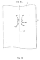
- the marking pattern MP is shown in Fig. 3.
- the marking pattern MP can be formed, using characters, marks, graphic symbols and the like, which comprise a dot array such as a 5 ⁇ 5 dot array.
- the pattern MP may have an arbitrary configuration which uses a plurality of characters, number symbols, marks, and the like, which comprise a dot array as shown in Fig. 4B.
- the marking pattern MP can be formed on both sides of the cut line 48 such that top and bottom directions of the marking patterns are opposite to each other.
- the marking head 40 and the X-ray film 12 are configured in the marking device 10 to oppose each other at a position at a short distance from the print roller 24 when the X-ray film 12 is wound onto the print roller 24.
- fogging which is generated in the X-ray film 12 by heating of dust and the like which is attached to the peripheral surface of the print roller 24 through the laser beams LB penetrating the X-ray film 12, is prevented.
- CO 2 -laser beams are used as one example of the laser beams LB in the marking device 10, and a laser oscillation tube for outputting the CO 2 -laser beams with a predetermined wavelength is used in the laser oscillation unit 44 of the marking head 40.
- convex dots 16A are formed on the X-ray film 12 by the laser beams LB emitted from the marking head 40, and characters, marks, and the like forming the marking pattern MP are formed by an array of the dots 16A.
- the wavelength (oscillation wavelength) ⁇ ( ⁇ m) of the laser beams LB which oscillate in the laser oscillation unit 44, the pulse width t ( ⁇ sec), which drives the laser oscillation unit 44, as the radiation time of the laser beams LB for forming one dot 16A, and, the energy density E (kw/cm 2 ) of the laser beams LB irradiated onto the X-ray film 12 are set in the embodiment in such a way that predetermined relations which have been set beforehand are satisfied.
- the marking pattern MP comprising the dots 16A and the dot arrays with excellent visibility is formed on the X-ray film 12.
- the X-ray film 12 absorbs the energy of the laser beams LB and is melted. At this time, the melting speed depends on the amount of the energy absorbed.
- the amount of energy absorbed by the X-ray film 12 changes according to the wavelength ⁇ of the laser beams LB, the energy density E of the laser beams LB, and the pulse width t of the radiation time of the laser beams LB.
- the wavelength ⁇ of the laser beams LB such as CO 2 laser beams is roughly divided into, for example, a 9-micrometer wavelength band such as 9.3 ⁇ m (9.3 ⁇ 10 -6 m) and 9.6 ⁇ m, and a 10-micrometer wavelength band such as 10.6 ⁇ m.
- areas A, B, and C, in which the dots 16A with excellent visibility can be formed are set, based on the wavelength ⁇ , the pulse width t, and the energy density E as shown in Fig. 5. Then, marking is executed according to the area A, B or C.
- the areas A and C are applied to the laser beams LB in the 9-micrometer wavelength band
- the area B is applied to the laser beams LB in the 10-micrometer wavelength band.
- the winding control device 36 controls starting of drawing-out of the X-ray film 12 from the delivery roll 50.
- the suction drum 32, and the like the X-ray film 12 is carried, and wound around the core 34 to form the winding roll 52.
- the suction drum 32 is controlled by the winding control device 36 to start air sucking while rotating, and the X-ray film 12 which is wound onto the outer peripheral surface is sucked and held. As a result, the X-ray film 12 is carried at a constant linear velocity. Moreover, the suction drum 32 applies predetermined tension to the X-ray film 12 by its own weight or an urging force.
- the rotational velocity (peripheral velocity) of the suction drum 32 becomes the linear velocity of the X-ray film 12, at which the film 12 is carried while being wound onto the print roller 24.
- the laser control device 42 detects the rotational velocity of the suction drum 32 by the rotary encoder 38 to monitor the carried length of the X-ray film 12.
- the driving signal for the laser oscillation unit 44 and the deflection signal for the beam deflection unit 46 are.output, such that both signals correspond to the pattern signal input from the winding control device 36.
- the X-ray film 12 is scanned and irradiated by the laser beams LB according to the pattern signal, and the marking pattern MP having the dot arrays according to the pattern signal is formed on the X-ray film 12.
- the X-ray film 12 absorbs the energy of the laser beams LB due to the beams LB being irradiated onto the emulsion layer 16 to cause melting.and deposition on the emulsion layer 16.
- Minute air bubbles 16B are generated in the emulsion layer 16 of the X-ray film 12 during the melting and deposition process, and the surface becomes convex due to the minute air bubbles 16B.
- Dots with excellent visibility can be obtained by making a diameter of the minute air bubbles 16B about 1 ⁇ m to 5 ⁇ m, by making an amount of convexity of the dots 16A due to the air bubbles 16B about 10 ⁇ m, and by making a diameter of the dots 16A about 200 ⁇ m (200 ⁇ 10 -6 m) .
- the radiation time of the laser beams LB is long, and the energy amount absorbed by the emulsion layer 16 is increased, melting of the emulsion layer 16 is advanced to generate a space between the base layer 14 and the emulsion layer 16, or to expose the base layer 14.
- the space generated between the base layer 14 and the emulsion layer 16 is different from the air bubbles 16B generated in the emulsion layer 16, that is, the space is larger, in comparison with the size of the air bubbles 16B.
- the space is generated, although the visibility of the dots 16A is improved immediately after radiation of the laser beams LB and before developing, the emulsion layer 16 at the upper part of the space is scattered or comes off due to developing processing to expose the base layer 14. As a result, the visibility of the dots 16A is reduced, or the dots 16A disappear.
- the output of the marking head 40 (the output of the laser oscillation unit 44) and the radiation time of the laser beams LB are set in order to impart energy for forming the proper dots 16A with excellent visibility.
- the wavelength ⁇ ( ⁇ m) of the laser beams LB using laser oscillation units with different oscillation wavelengths (wavelength ⁇ ) and different outputs are switched, and the pulse width t ( ⁇ sec) of the radiation time and the energy density E (kw/cm 2 ) of the laser beams LB are changed to make visibility evaluation of the dots 16A at irradiating the laser beams LB, fogging evaluation, and over-all evaluation of finished quality including the product quality.
- conditions for marking of the dots 16A on the X-ray film 12 with excellent visibility and without reduction in the product quality are set.
- Fig. 6 shows a schematic configuration of a testing device 60 applied to the above-described evaluation.
- laser oscillation tubes 44A, 44B, 44C are alternately disposed in a marking head 62 as a laser oscillation unit 44.
- the laser beams LB having wavelength ⁇ of 9.3 ⁇ m and 9.6 ⁇ m are used as those of the 9-micrometer band, and the laser beams LB having wavelength ⁇ of 10.6 ⁇ m are applied as those of the 10-micrometer band.
- the oscillation wavelength (wavelength ⁇ ) of the laser oscillation tube 44A is 9.3 ⁇ m
- the oscillation wavelength of the laser oscillation tube 44B is 9.6 ⁇ m
- the oscillation wavelength of the laser oscillation tube 44C is 10.6 ⁇ m.
- These laser oscillation tubes 44A through 44C emit the laser beams LB with a beam diameter of about 4 mm.
- a laser control device 64 outputs a pulse signal with a predetermined pulse width t ( ⁇ sec) for driving the laser oscillation tubes 44A through 44C. At this time, the laser control device 64 can arbitrarily adjust the pulse width t.
- an evaluation sample 70 is mounted for use on an X-Y mobile table 72 by which the evaluation sample 70 can be moved in the horizontal direction.
- Tables 1 through 4 show testing results which were obtained under conditions in which, while the pulse widths t ( ⁇ sec) are constant, the wavelengths ⁇ ( ⁇ m) of the laser beams LB, and the energy densities E (kw/cm 2 ) of the laser beams LB on the evaluation sample 70 are changed.
- the pulse widths t in Tables 1 through 4 are 3 ⁇ sec, 10 ⁇ sec, 20 ⁇ sec, and 30 ⁇ sec, respectively.
- Tables 5 through 12 show testing results which were obtained under conditions in which, while the energy densities E (kw/cm 2 ) of the laser beams LB are constant, the wavelengths ⁇ ( ⁇ m) of the laser beams LB, and the pulse widths t ( ⁇ sec) of the laser beams LB are changed.
- the energy densities E (kw/cm 2 ) in Tables 5 through 9 are 200 kw/cm 2 , 500 kw/cm 2 , 600 kw/cm 2 , 750 kw/cm 2 , and 1000 kw/cm 2 , respectively.
- the energy densities E (kw/cm 2 ) in Tables 10 through 12 are 5 kw/cm 2 , 80 kw/cm 2 , and 50 kw/cm 2 , respectively.
- Table 5 Energy density 200 kw/cm 2 Radiation wave-length ( ⁇ m) Pulse width (t) ( ⁇ 10 -5 see) Visibility evaluation Fogging evaluation Over-all evaluation 9.3, 9.6 10.6 9.3, 9.6 10.6 9.3, 9.6 10.6 9.3, 9.6 10.6 9.3, 9.6 10.6 9.3, 9.6 10.6 1 ⁇ ⁇ - - ⁇ ⁇ 3 ⁇ ⁇ - - ⁇ ⁇ 5 ⁇ ⁇ - - ⁇ ⁇ 10 ⁇ ⁇ - - ⁇ 15 O ⁇ O - O ⁇ 20 O ⁇ O - O ⁇ 25 O ⁇ O - O ⁇ 30 O ⁇ O - O ⁇ 35 ⁇ ⁇ - ⁇ ⁇ Table 6 Energy density 500 kw/cm 2 Radiation
- the marking pattern MP of the dot arrays comprising reasonable dots 16A can be formed in the area A without reduction in finished quality in the X-ray film 12 (evaluation sample 70), using laser beams LB in the 9-micrometer band with a wavelength ⁇ of 9.3 ⁇ m or 9.6 ⁇ m for the pulse widths t within a range of equal to or larger than 3 ⁇ sec and smaller than 30 ⁇ sec. As shown in Fig.
- the area A is between a line segment A 1 and a line segment A 2 ; it is difficult in an area in which the energy density E is lower than the line segment A 1 to impart enough energy to the X-ray film 12; and, when the energy density E is higher than the line segment A 2 , the energy amount becomes too, thereby causing large exposure, fogging, and the like in the base layer 14.
- the energy density E of the laser beams LB on the evaluation sample 70 (X-ray film 12) can be expressed by an approximation based on the following linear function with a variable of the pulse width t as the radiation time of the laser beams LB.
- E ⁇ t + ⁇ (wherein, ⁇ and ⁇ are constants)
- temperature increase is caused in the X-ray film 12 because the X-ray film 12 is heated by radiation of the laser beams LB.
- defective performance such as sensitization and desensitization, is caused on the X-ray film 12 because a state in which the temperature is increased is maintained.
- the air layer has an adiabatic effect between the X-ray film 12 and the print roller 24 to cause reduction in the heat dispersion from the X-ray film 12.
- the outer peripheral part of the print roller 24 is formed of a metal material with a thermal conductivity ⁇ of 15 W/(m ⁇ K) or more, such as SUS (stainless steel), iron, aluminum, and copper, and heat generated by radiation of the laser beams LB is dispersed from the X-ray film 12, whereby the heat is never accumulated, the marking pattern MP with excellent visibility can be formed without causing defective performance such as sensitization and desensitization in the X-ray film 12.
- Table 17 shows the contact heat transfer coefficient H and the evaluation of the finished quality when the linear velocity V was changed while the web tension T of the X-ray film 12 was constant.
- Table 16 Web tension T (kg/m) Contact heat transfer coefficient h Print quality (finished quality) 4 431.2 ⁇ 5 480.0 O 7 556.3 O 8 588.4 O 12 689.8 O 16 763.8 O 20 821.4 O
- Table 17 Line speed V (m/min) Contact heat transfer coefficient H (W/(m 2 ⁇ K)) Print quality (finished quality) 240 470.7 ⁇ 230 480.0 O 200 511.5 O 180 535.9 O 150 579.2 O
- the contact heat transfer coefficient H is increased when the web tension T of the X-ray film 12 is increased. Moreover, as shown in Table 17, the contact heat transfer coefficient H is decreased when the linear velocity V of the X-ray film 12 is increased.
- high-quality finish is obtained for the X-ray film 12 with a contact heat transfer coefficient H of 480 W/(m 2 ⁇ K) or more, and sensitization and desensitization is caused for the X-ray film 12 with a contact heat transfer coefficient H of 470.7 W/(m 2 ⁇ K) or less.
- the linear velocity V for the above-described cases are 230 m/min and 240 m/min, respectively.
- the upper limit of the web tension T may be controlled so as to be within a range in which no damage is caused in the X-ray film 12.
- the linear velocity V may be set from the above-described range in such a way that a desired contact heat transfer coefficient H is obtained, based on the productivity, the time required for forming suitable dots 16A with the laser beams LB, and the like.
- reliable heat dispersion for the material to be printed can be realized by making the contact heat transfer coefficient H between the material to be printed and the backup roller 475 (W/m 2 ⁇ K) or more, and preferably 480 (W/m 2 ⁇ K) or more.
Landscapes
- Physics & Mathematics (AREA)
- General Physics & Mathematics (AREA)
- Optics & Photonics (AREA)
- Chemical & Material Sciences (AREA)
- Engineering & Computer Science (AREA)
- Materials Engineering (AREA)
- Laser Beam Processing (AREA)
- Laser Beam Printer (AREA)
- Lasers (AREA)
- Dot-Matrix Printers And Others (AREA)
- Thermal Transfer Or Thermal Recording In General (AREA)
Applications Claiming Priority (3)
| Application Number | Priority Date | Filing Date | Title |
|---|---|---|---|
| JP2003123546A JP2004322580A (ja) | 2003-04-28 | 2003-04-28 | レーザーマーキング方法 |
| JP2003160366A JP2004358824A (ja) | 2003-06-05 | 2003-06-05 | レーザーマーキング方法及びレーザーマーキング装置 |
| EP04009955A EP1473590B1 (de) | 2003-04-28 | 2004-04-27 | Vorrichtung und Verfahren zur Lasermarkierung |
Related Parent Applications (1)
| Application Number | Title | Priority Date | Filing Date |
|---|---|---|---|
| EP04009955A Division EP1473590B1 (de) | 2003-04-28 | 2004-04-27 | Vorrichtung und Verfahren zur Lasermarkierung |
Publications (2)
| Publication Number | Publication Date |
|---|---|
| EP1677145A1 true EP1677145A1 (de) | 2006-07-05 |
| EP1677145B1 EP1677145B1 (de) | 2007-11-07 |
Family
ID=32993100
Family Applications (2)
| Application Number | Title | Priority Date | Filing Date |
|---|---|---|---|
| EP06007582A Expired - Lifetime EP1677145B1 (de) | 2003-04-28 | 2004-04-27 | Vorrichtung und Verfahren zur Lasermarkierung |
| EP04009955A Expired - Lifetime EP1473590B1 (de) | 2003-04-28 | 2004-04-27 | Vorrichtung und Verfahren zur Lasermarkierung |
Family Applications After (1)
| Application Number | Title | Priority Date | Filing Date |
|---|---|---|---|
| EP04009955A Expired - Lifetime EP1473590B1 (de) | 2003-04-28 | 2004-04-27 | Vorrichtung und Verfahren zur Lasermarkierung |
Country Status (5)
| Country | Link |
|---|---|
| US (2) | US7321377B2 (de) |
| EP (2) | EP1677145B1 (de) |
| CN (1) | CN100379566C (de) |
| AT (2) | ATE377774T1 (de) |
| DE (2) | DE602004009855T2 (de) |
Families Citing this family (7)
| Publication number | Priority date | Publication date | Assignee | Title |
|---|---|---|---|---|
| JP2005223878A (ja) * | 2004-01-05 | 2005-08-18 | Ricoh Co Ltd | 画像読み取り装置および画像読み取り装置付き記録装置 |
| CN102198758A (zh) * | 2010-03-24 | 2011-09-28 | 苏州楚天光电设备有限公司 | 嵌入式网络控制激光标刻系统 |
| GB2520945A (en) * | 2013-12-03 | 2015-06-10 | Spi Lasers Uk Ltd | Method for laser marking an anodized metal surface with a desired colour |
| CN104608515A (zh) * | 2015-02-06 | 2015-05-13 | 苏州创轩激光科技有限公司 | 一种为陶瓷打标的激光加工方法 |
| CN104999814B (zh) * | 2015-07-28 | 2017-08-01 | 深圳泰德激光科技有限公司 | 激光打标控制方法以及振镜式激光打标系统 |
| CN108162565B (zh) * | 2016-03-31 | 2019-11-08 | 马鞍山联洪合成材料有限公司 | 一种发泡型补强胶片生产装置的生产工艺 |
| CN109458899B (zh) * | 2018-09-21 | 2020-12-18 | 大族激光科技产业集团股份有限公司 | 一种快速判定打标线宽的方法 |
Citations (5)
| Publication number | Priority date | Publication date | Assignee | Title |
|---|---|---|---|---|
| JPS5919253A (ja) * | 1982-07-23 | 1984-01-31 | Sony Corp | 情報記録媒体 |
| US5940115A (en) * | 1996-06-26 | 1999-08-17 | Konica Corporation | Method of irradiating photosensitive material with a laser beam of a particular type |
| JP3202977B2 (ja) | 1999-10-18 | 2001-08-27 | 日東電工株式会社 | フレキシブル配線板の加工方法およびフレキシブル配線板の固定装置 |
| JP2001239700A (ja) | 2000-01-25 | 2001-09-04 | Eastman Kodak Co | 感光材料ウェブへのレーザーマーキング記録装置 |
| JP2001239378A (ja) | 2000-01-25 | 2001-09-04 | Eastman Kodak Co | 感光ウェブに印をレーザマーキングする装置 |
Family Cites Families (4)
| Publication number | Priority date | Publication date | Assignee | Title |
|---|---|---|---|---|
| JP4322325B2 (ja) * | 1997-07-08 | 2009-08-26 | 東北リコー株式会社 | 製版装置 |
| US6556273B1 (en) * | 1999-11-12 | 2003-04-29 | Eastman Kodak Company | System for providing pre-processing machine readable encoded information markings in a motion picture film |
| EP1355191B1 (de) | 2002-04-15 | 2007-11-07 | FUJIFILM Corporation | Lasermarkierung auf lichtempfindlichem Material und lichtempfindliches Material beinhaltend besagte Markierung |
| US7199812B2 (en) | 2002-10-28 | 2007-04-03 | Fujifilm Corporation | Laser marking method |
-
2004
- 2004-04-23 CN CNB2004100351201A patent/CN100379566C/zh not_active Expired - Fee Related
- 2004-04-26 US US10/831,349 patent/US7321377B2/en not_active Expired - Fee Related
- 2004-04-27 AT AT04009955T patent/ATE377774T1/de not_active IP Right Cessation
- 2004-04-27 DE DE602004009855T patent/DE602004009855T2/de not_active Expired - Lifetime
- 2004-04-27 EP EP06007582A patent/EP1677145B1/de not_active Expired - Lifetime
- 2004-04-27 AT AT06007582T patent/ATE377775T1/de not_active IP Right Cessation
- 2004-04-27 EP EP04009955A patent/EP1473590B1/de not_active Expired - Lifetime
- 2004-04-27 DE DE602004009957T patent/DE602004009957T2/de not_active Expired - Lifetime
-
2007
- 2007-11-26 US US11/944,999 patent/US20080136893A1/en not_active Abandoned
Patent Citations (6)
| Publication number | Priority date | Publication date | Assignee | Title |
|---|---|---|---|---|
| JPS5919253A (ja) * | 1982-07-23 | 1984-01-31 | Sony Corp | 情報記録媒体 |
| US5940115A (en) * | 1996-06-26 | 1999-08-17 | Konica Corporation | Method of irradiating photosensitive material with a laser beam of a particular type |
| JP3191201B2 (ja) | 1996-06-26 | 2001-07-23 | コニカ株式会社 | 感光材料へのマーキング方法 |
| JP3202977B2 (ja) | 1999-10-18 | 2001-08-27 | 日東電工株式会社 | フレキシブル配線板の加工方法およびフレキシブル配線板の固定装置 |
| JP2001239700A (ja) | 2000-01-25 | 2001-09-04 | Eastman Kodak Co | 感光材料ウェブへのレーザーマーキング記録装置 |
| JP2001239378A (ja) | 2000-01-25 | 2001-09-04 | Eastman Kodak Co | 感光ウェブに印をレーザマーキングする装置 |
Non-Patent Citations (1)
| Title |
|---|
| PATENT ABSTRACTS OF JAPAN vol. 0081, no. 09 (P - 275) 22 May 1984 (1984-05-22) * |
Also Published As
| Publication number | Publication date |
|---|---|
| ATE377775T1 (de) | 2007-11-15 |
| EP1473590A1 (de) | 2004-11-03 |
| DE602004009957D1 (de) | 2007-12-20 |
| ATE377774T1 (de) | 2007-11-15 |
| US20040263604A1 (en) | 2004-12-30 |
| DE602004009957T2 (de) | 2008-08-28 |
| CN100379566C (zh) | 2008-04-09 |
| US7321377B2 (en) | 2008-01-22 |
| DE602004009855T2 (de) | 2008-09-18 |
| EP1677145B1 (de) | 2007-11-07 |
| US20080136893A1 (en) | 2008-06-12 |
| DE602004009855D1 (de) | 2007-12-20 |
| CN1541846A (zh) | 2004-11-03 |
| EP1473590B1 (de) | 2007-11-07 |
Similar Documents
| Publication | Publication Date | Title |
|---|---|---|
| US20080136893A1 (en) | Device and method for laser marking | |
| EP1726989A2 (de) | Lasermarkierung auf lichtempfindlichem Material und lichtempfindliches Material mit der Markierung | |
| EP1364798A1 (de) | Vorrichtung zum Lasermarkieren | |
| US7369152B2 (en) | Laser marking method | |
| US6924829B2 (en) | Web processing method and web processing device | |
| US20030164873A1 (en) | Photosensitive material and laser marking method | |
| JP4005454B2 (ja) | レーザーマーキング方法 | |
| JP2004322580A (ja) | レーザーマーキング方法 | |
| JP2004358824A (ja) | レーザーマーキング方法及びレーザーマーキング装置 | |
| JP4111783B2 (ja) | レーザーマーキング方法 | |
| JP4198440B2 (ja) | レーザーマーキング方法 | |
| JP4185319B2 (ja) | レーザーマーキング方法 | |
| JP4005500B2 (ja) | レーザーマーキング方法 | |
| JP2004086094A (ja) | レーザーマーキング方法 | |
| JP3910439B2 (ja) | マーキング方法 | |
| JP2003311449A (ja) | レーザーマーキング方法及び装置 | |
| JP4137495B2 (ja) | レーザーマーキング方法及び感光材料 | |
| JP2003251937A (ja) | マーキング方法、マーキング装置及び感光材料 | |
| JP2004042072A (ja) | レーザーマーキング方法及びマーキング装置 | |
| JP3816414B2 (ja) | レーザーマーキング方法 | |
| JP3911149B2 (ja) | 感光材料及びマーキング方法 | |
| EP1365281A1 (de) | System und Verfahren zur Lasermarkierung | |
| JPS63133134A (ja) | 感熱複写装置 | |
| JP2005254646A (ja) | 画像形成機構及びその制御方法 | |
| JPH0462067A (ja) | レーザー書き込み構造を備えた印刷機 |
Legal Events
| Date | Code | Title | Description |
|---|---|---|---|
| PUAI | Public reference made under article 153(3) epc to a published international application that has entered the european phase |
Free format text: ORIGINAL CODE: 0009012 |
|
| 17P | Request for examination filed |
Effective date: 20060411 |
|
| AC | Divisional application: reference to earlier application |
Ref document number: 1473590 Country of ref document: EP Kind code of ref document: P |
|
| AK | Designated contracting states |
Kind code of ref document: A1 Designated state(s): AT BE BG CH CY CZ DE DK EE ES FI FR GB GR HU IE IT LI LU MC NL PL PT RO SE SI SK TR |
|
| RIN1 | Information on inventor provided before grant (corrected) |
Inventor name: NISHIDA, HIROYUKI,C/O FUJI PHOTO FILM CO., LTD. Inventor name: ENDO, KEISUKE,C/O FUJI PHOTO FILM CO., LTD. |
|
| AKX | Designation fees paid |
Designated state(s): AT BE BG CH CY CZ DE DK EE ES FI FR GB GR HU IE IT LI LU MC NL PL PT RO SE SI SK TR |
|
| RAP1 | Party data changed (applicant data changed or rights of an application transferred) |
Owner name: FUJIFILM CORPORATION |
|
| GRAP | Despatch of communication of intention to grant a patent |
Free format text: ORIGINAL CODE: EPIDOSNIGR1 |
|
| GRAS | Grant fee paid |
Free format text: ORIGINAL CODE: EPIDOSNIGR3 |
|
| GRAA | (expected) grant |
Free format text: ORIGINAL CODE: 0009210 |
|
| AC | Divisional application: reference to earlier application |
Ref document number: 1473590 Country of ref document: EP Kind code of ref document: P |
|
| AK | Designated contracting states |
Kind code of ref document: B1 Designated state(s): AT BE BG CH CY CZ DE DK EE ES FI FR GB GR HU IE IT LI LU MC NL PL PT RO SE SI SK TR |
|
| REG | Reference to a national code |
Ref country code: GB Ref legal event code: FG4D |
|
| REG | Reference to a national code |
Ref country code: IE Ref legal event code: FG4D |
|
| REG | Reference to a national code |
Ref country code: CH Ref legal event code: EP |
|
| REF | Corresponds to: |
Ref document number: 602004009957 Country of ref document: DE Date of ref document: 20071220 Kind code of ref document: P |
|
| PG25 | Lapsed in a contracting state [announced via postgrant information from national office to epo] |
Ref country code: ES Free format text: LAPSE BECAUSE OF FAILURE TO SUBMIT A TRANSLATION OF THE DESCRIPTION OR TO PAY THE FEE WITHIN THE PRESCRIBED TIME-LIMIT Effective date: 20080218 Ref country code: NL Free format text: LAPSE BECAUSE OF FAILURE TO SUBMIT A TRANSLATION OF THE DESCRIPTION OR TO PAY THE FEE WITHIN THE PRESCRIBED TIME-LIMIT Effective date: 20071107 Ref country code: LI Free format text: LAPSE BECAUSE OF FAILURE TO SUBMIT A TRANSLATION OF THE DESCRIPTION OR TO PAY THE FEE WITHIN THE PRESCRIBED TIME-LIMIT Effective date: 20071107 Ref country code: SE Free format text: LAPSE BECAUSE OF FAILURE TO SUBMIT A TRANSLATION OF THE DESCRIPTION OR TO PAY THE FEE WITHIN THE PRESCRIBED TIME-LIMIT Effective date: 20080207 Ref country code: CH Free format text: LAPSE BECAUSE OF FAILURE TO SUBMIT A TRANSLATION OF THE DESCRIPTION OR TO PAY THE FEE WITHIN THE PRESCRIBED TIME-LIMIT Effective date: 20071107 |
|
| NLV1 | Nl: lapsed or annulled due to failure to fulfill the requirements of art. 29p and 29m of the patents act | ||
| PG25 | Lapsed in a contracting state [announced via postgrant information from national office to epo] |
Ref country code: SI Free format text: LAPSE BECAUSE OF FAILURE TO SUBMIT A TRANSLATION OF THE DESCRIPTION OR TO PAY THE FEE WITHIN THE PRESCRIBED TIME-LIMIT Effective date: 20071107 Ref country code: BG Free format text: LAPSE BECAUSE OF FAILURE TO SUBMIT A TRANSLATION OF THE DESCRIPTION OR TO PAY THE FEE WITHIN THE PRESCRIBED TIME-LIMIT Effective date: 20080207 Ref country code: PL Free format text: LAPSE BECAUSE OF FAILURE TO SUBMIT A TRANSLATION OF THE DESCRIPTION OR TO PAY THE FEE WITHIN THE PRESCRIBED TIME-LIMIT Effective date: 20071107 |
|
| REG | Reference to a national code |
Ref country code: CH Ref legal event code: PL |
|
| PG25 | Lapsed in a contracting state [announced via postgrant information from national office to epo] |
Ref country code: AT Free format text: LAPSE BECAUSE OF FAILURE TO SUBMIT A TRANSLATION OF THE DESCRIPTION OR TO PAY THE FEE WITHIN THE PRESCRIBED TIME-LIMIT Effective date: 20071107 |
|
| PG25 | Lapsed in a contracting state [announced via postgrant information from national office to epo] |
Ref country code: DK Free format text: LAPSE BECAUSE OF FAILURE TO SUBMIT A TRANSLATION OF THE DESCRIPTION OR TO PAY THE FEE WITHIN THE PRESCRIBED TIME-LIMIT Effective date: 20071107 Ref country code: CZ Free format text: LAPSE BECAUSE OF FAILURE TO SUBMIT A TRANSLATION OF THE DESCRIPTION OR TO PAY THE FEE WITHIN THE PRESCRIBED TIME-LIMIT Effective date: 20071107 |
|
| ET | Fr: translation filed | ||
| PG25 | Lapsed in a contracting state [announced via postgrant information from national office to epo] |
Ref country code: RO Free format text: LAPSE BECAUSE OF FAILURE TO SUBMIT A TRANSLATION OF THE DESCRIPTION OR TO PAY THE FEE WITHIN THE PRESCRIBED TIME-LIMIT Effective date: 20071107 Ref country code: SK Free format text: LAPSE BECAUSE OF FAILURE TO SUBMIT A TRANSLATION OF THE DESCRIPTION OR TO PAY THE FEE WITHIN THE PRESCRIBED TIME-LIMIT Effective date: 20071107 Ref country code: BE Free format text: LAPSE BECAUSE OF FAILURE TO SUBMIT A TRANSLATION OF THE DESCRIPTION OR TO PAY THE FEE WITHIN THE PRESCRIBED TIME-LIMIT Effective date: 20071107 |
|
| PLBE | No opposition filed within time limit |
Free format text: ORIGINAL CODE: 0009261 |
|
| STAA | Information on the status of an ep patent application or granted ep patent |
Free format text: STATUS: NO OPPOSITION FILED WITHIN TIME LIMIT |
|
| PG25 | Lapsed in a contracting state [announced via postgrant information from national office to epo] |
Ref country code: PT Free format text: LAPSE BECAUSE OF FAILURE TO SUBMIT A TRANSLATION OF THE DESCRIPTION OR TO PAY THE FEE WITHIN THE PRESCRIBED TIME-LIMIT Effective date: 20080407 |
|
| 26N | No opposition filed |
Effective date: 20080808 |
|
| PG25 | Lapsed in a contracting state [announced via postgrant information from national office to epo] |
Ref country code: MC Free format text: LAPSE BECAUSE OF NON-PAYMENT OF DUE FEES Effective date: 20080430 |
|
| PG25 | Lapsed in a contracting state [announced via postgrant information from national office to epo] |
Ref country code: GR Free format text: LAPSE BECAUSE OF FAILURE TO SUBMIT A TRANSLATION OF THE DESCRIPTION OR TO PAY THE FEE WITHIN THE PRESCRIBED TIME-LIMIT Effective date: 20080208 Ref country code: EE Free format text: LAPSE BECAUSE OF FAILURE TO SUBMIT A TRANSLATION OF THE DESCRIPTION OR TO PAY THE FEE WITHIN THE PRESCRIBED TIME-LIMIT Effective date: 20071107 |
|
| PG25 | Lapsed in a contracting state [announced via postgrant information from national office to epo] |
Ref country code: FI Free format text: LAPSE BECAUSE OF FAILURE TO SUBMIT A TRANSLATION OF THE DESCRIPTION OR TO PAY THE FEE WITHIN THE PRESCRIBED TIME-LIMIT Effective date: 20071107 |
|
| PG25 | Lapsed in a contracting state [announced via postgrant information from national office to epo] |
Ref country code: IE Free format text: LAPSE BECAUSE OF NON-PAYMENT OF DUE FEES Effective date: 20080428 |
|
| PG25 | Lapsed in a contracting state [announced via postgrant information from national office to epo] |
Ref country code: CY Free format text: LAPSE BECAUSE OF FAILURE TO SUBMIT A TRANSLATION OF THE DESCRIPTION OR TO PAY THE FEE WITHIN THE PRESCRIBED TIME-LIMIT Effective date: 20071107 |
|
| PG25 | Lapsed in a contracting state [announced via postgrant information from national office to epo] |
Ref country code: LU Free format text: LAPSE BECAUSE OF NON-PAYMENT OF DUE FEES Effective date: 20080427 Ref country code: HU Free format text: LAPSE BECAUSE OF FAILURE TO SUBMIT A TRANSLATION OF THE DESCRIPTION OR TO PAY THE FEE WITHIN THE PRESCRIBED TIME-LIMIT Effective date: 20080508 |
|
| PG25 | Lapsed in a contracting state [announced via postgrant information from national office to epo] |
Ref country code: TR Free format text: LAPSE BECAUSE OF FAILURE TO SUBMIT A TRANSLATION OF THE DESCRIPTION OR TO PAY THE FEE WITHIN THE PRESCRIBED TIME-LIMIT Effective date: 20071107 |
|
| PG25 | Lapsed in a contracting state [announced via postgrant information from national office to epo] |
Ref country code: IT Free format text: LAPSE BECAUSE OF NON-PAYMENT OF DUE FEES Effective date: 20080430 |
|
| PGFP | Annual fee paid to national office [announced via postgrant information from national office to epo] |
Ref country code: GB Payment date: 20140423 Year of fee payment: 11 |
|
| PGFP | Annual fee paid to national office [announced via postgrant information from national office to epo] |
Ref country code: FR Payment date: 20140409 Year of fee payment: 11 Ref country code: DE Payment date: 20140430 Year of fee payment: 11 |
|
| REG | Reference to a national code |
Ref country code: DE Ref legal event code: R119 Ref document number: 602004009957 Country of ref document: DE |
|
| GBPC | Gb: european patent ceased through non-payment of renewal fee |
Effective date: 20150427 |
|
| PG25 | Lapsed in a contracting state [announced via postgrant information from national office to epo] |
Ref country code: GB Free format text: LAPSE BECAUSE OF NON-PAYMENT OF DUE FEES Effective date: 20150427 Ref country code: DE Free format text: LAPSE BECAUSE OF NON-PAYMENT OF DUE FEES Effective date: 20151103 |
|
| REG | Reference to a national code |
Ref country code: FR Ref legal event code: ST Effective date: 20151231 |
|
| PG25 | Lapsed in a contracting state [announced via postgrant information from national office to epo] |
Ref country code: FR Free format text: LAPSE BECAUSE OF NON-PAYMENT OF DUE FEES Effective date: 20150430 |