EP1677398A2 - Dispositif dérivateur de surtensions - Google Patents
Dispositif dérivateur de surtensions Download PDFInfo
- Publication number
- EP1677398A2 EP1677398A2 EP05027579A EP05027579A EP1677398A2 EP 1677398 A2 EP1677398 A2 EP 1677398A2 EP 05027579 A EP05027579 A EP 05027579A EP 05027579 A EP05027579 A EP 05027579A EP 1677398 A2 EP1677398 A2 EP 1677398A2
- Authority
- EP
- European Patent Office
- Prior art keywords
- housing part
- overvoltage protection
- protection device
- housing
- electrodes
- Prior art date
- Legal status (The legal status is an assumption and is not a legal conclusion. Google has not performed a legal analysis and makes no representation as to the accuracy of the status listed.)
- Granted
Links
Images

Classifications
-
- H—ELECTRICITY
- H01—ELECTRIC ELEMENTS
- H01T—SPARK GAPS; OVERVOLTAGE ARRESTERS USING SPARK GAPS; SPARKING PLUGS; CORONA DEVICES; GENERATING IONS TO BE INTRODUCED INTO NON-ENCLOSED GASES
- H01T4/00—Overvoltage arresters using spark gaps
- H01T4/10—Overvoltage arresters using spark gaps having a single gap or a plurality of gaps in parallel
-
- H—ELECTRICITY
- H01—ELECTRIC ELEMENTS
- H01T—SPARK GAPS; OVERVOLTAGE ARRESTERS USING SPARK GAPS; SPARKING PLUGS; CORONA DEVICES; GENERATING IONS TO BE INTRODUCED INTO NON-ENCLOSED GASES
- H01T4/00—Overvoltage arresters using spark gaps
- H01T4/04—Housings
Definitions
- the invention relates to an overvoltage protection device for use in the power supply, in particular low-voltage networks, having a housing, having a first electrode, having at least one second electrode, an arc-shaped combustion chamber formed in the interior of the housing between the two electrodes, and one between the two electrodes formed breakdown spark gap, wherein when igniting the breakdown spark gap between the two electrodes, an arc is formed.
- Electrical, but especially electronic measuring, control, regulating and switching circuits are sensitive to transient overvoltages, as may occur in particular by atmospheric discharges, but also by switching operations or short circuits in power grids.
- This sensitivity has increased as electronic components, in particular transistors and thyristors, are used; above all, increasingly used integrated circuits are to a great extent endangered by transient overvoltages.
- Overvoltages are all voltages that are above the upper tolerance limit of the rated voltage. These include, above all, the transient overvoltages that can occur due to atmospheric discharges, but also through switching operations or short circuits in power supply networks and can be galvanically, inductively or capacitively coupled into electrical circuits.
- overvoltage protection devices In order to protect electrical or electronic circuits, especially electronic measuring, control, and circuits, especially telecommunications equipment and systems, wherever they are used against transient overvoltages, overvoltage protection devices have been developed and for more than twenty Known years ago.
- An essential part of overvoltage protection of the type in question here is at least one spark gap, which responds at a certain overvoltage, the Anschschreib, and thus prevents that in the protected by an overvoltage protection circuit overvoltages occur, which are greater than the Anschspaunung the spark gap.
- the overvoltage protection device has two electrodes and a breakdown spark gap existing between the two electrodes.
- a breakdown spark gap can be both an air breakdown spark gap and a breakdown spark gap in which there is no air, but another gas between the electrodes.
- overvoltage protection devices with a breakdown spark gap there are overvoltage protection devices with a rollover spark gap, which occurs when responding a sliding discharge.
- Overvoltage protection devices with a breakdown spark gap have over Matternapssschutzeinnchtungen with a flashover spark gap the advantage of a higher Stoßstromtragfahtechnik, but the disadvantage of a higher - and not very constant - Anschschreib. Therefore, various overvoltage protection devices have already been proposed with a breakdown spark gap which have been improved with respect to the response voltage. In this case, ignition aids have been realized in various ways in the region of the electrodes or the effective between the electrodes breakdown spark gap, z. B.
- the ignition aid as "active ignition aid” is formed, namely the fact that in addition to the two electrodes - there referred to as main electrodes - two ignition electrodes are provided. These two ignition electrodes form a second, serving as a spark gap breakdown spark gap.
- the overvoltage protection device belongs to the Zünd Anlagen except the spark gap nor a firing circuit with an ignition switch.
- the ignition circuit with the ignition switching element ensures a response of the spark gap.
- the two ignition electrodes are arranged with respect to the two main electrodes such that the fact that the spark gap has addressed, also the breakdown spark gap between the two main electrodes, responsive.
- the starting aids lead to an improved, namely lower and more constant response voltage.
- overvoltage protection devices of the type in question - with or without the use of an ignition aid - arises when igniting the breakdown spark gap by the resulting arc a mitimpedante connection between the two electrodes.
- the transient surge current to be dissipated flows, intentionally, via this low-impedance connection.
- an undesired follow-on current then follows via the low-impedance connection of the overvoltage protection device, so that efforts are made to extinguish the arc as quickly as possible after the discharge process has been completed.
- One way to achieve this goal is to increase the arc length and thus the arc voltage after the response of the spark gap.
- the low-impedance connection between the two electrodes is first interrupted, the space between the two electrodes, ie. H. the arc combustion chamber, however, is still almost completely filled with plasma. Due to the existing plasma, the response voltage between the two electrodes is so reduced that it can come even with applied operating voltage to a renewed ignition of the breakdown spark gap. This problem occurs especially when the overvoltage protection device has an encapsulated or only half-open housing, because then cooling or volatilization of the plasma is prevented by the substantially closed housing.
- the invention is based on the object, an overvoltage protection device of the type described above educate so that the occurrence of a Netz Steinstroms and a renewed ignition of Dwchschlag spark gap is prevented even more reliable.
- the overvoltage protection device described above in that at least one outflow and cooling channel is formed in the housing, through which that is plasma from the arc combustion chamber can emerge, wherein the outflow and cooling channel extends in the longitudinal direction of the housing and is helically formed by the helical formation of the outflow and cooling channel, this has a length which may be many times greater than the length of the housing.
- the outflow and cooling channel can have a relatively large cross section, so that there is a rapid reduction of the high pressure inside the housing and thus to a rapid Pressure relief of the interior area comes. Due to the rapid removal of the trapped in the housing thermal energy to the outside damage to the inside of the housing arranged components, in particular of plastic parts prevented.
- the outflow and cooling channel is realized in that the housing is formed in two parts, wherein the two housing parts are arranged coaxially to each other, and formed the space between the two housing parts as outflow and cooling channel for the ionized gas is.
- the inner housing part has an external thread and the outer housing part has a corresponding internal thread, so that in the assembled state of the overvoltage protection device, the inner housing part is screwed into the outer housing part. Due to the bipartite nature of the housing and the utilization or formation of the thread between the inner housing part and the outer housing part as outflow and cooling channel, a maximum area for cooling the hot plasma is available.
- the external thread of the inner housing part and / or the internal thread of the outer housing part is partially interrupted, so that between the inner housing part and the outer housing part one or more chambers are formed.
- the plasma can then continue to cool without requiring a corresponding additional volume inside the surge protector is required are the two housing parts made of steel, so the housing relative to the other components of the surge protector the largest mass for temporarily storing the thermal energy.
- the steel housing has a much higher heat capacity and higher heat resistance compared to the insulating serving plastic parts inside the housing, so that in connection with the large surface of the steel housing or the two housing parts not only a good intermediate storage of thennischen energy in the outdoor area Overvoltage protection device, but also a direct energy delivery to the environment is possible.
- the pressure load receptacle of the housing can be further increased in that the inner housing part has an at least partially conical outer periphery and the outer housing part has an at least partially conical inner circumference, so that the screw connection between the inner housing part and the outer housing part is conical.
- This conicity of the screw allows formation of the inner housing part and the outer housing part such that the two housing parts facing away from each other Ends at which the two housing parts each have to absorb the pressure alone, have the maximum wall thickness.
- the wall thickness of the inner and the outer housing part tapers, so that where the pressure load for the individual housing parts is the lowest, and the wall thickness is minimal.
- the conical configuration of the two housing parts that the housing has both a constant inner diameter and a constant outer diameter, whereby a high utilization of the existing volume and thus achieved given requirements a small size can be.
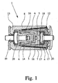
- Fig. 1 shows an embodiment of an overvoltage protection device 1 according to the invention, with a housing 2, which is shown in more detail in FIGS. 2 and 3 again.
- a housing 2 which is shown in more detail in FIGS. 2 and 3 again.
- an arc combustion chamber 5 is formed to the overvoltage protection device 1 in addition to the housing 2 in particular two electrodes 3 and 4, wherein the two electrodes 3 and 4 are opposite to each other and between them.
- the arc combustion chamber 5 is here - which is not apparent from the sectional view of FIG. 1 is - formed so that it connects the two electrodes 3, 4 with each other, wherein the arc combustion chamber 5, however, partially extends obliquely to the longitudinal extension of the overvoltage protection device 1.
- a discharge space or discharge channel which extends obliquely to the direction of the electric field of an applied mains voltage, so that the distance to be overcome by the arc between the two electrodes 3, 4 has a transverse component to the electric field.
- the electrical voltage applied to the two electrodes 3, 4 can no longer accelerate continuously from one electrode to the other electrode after ignition of the breakdown spark gap in the arc combustion chamber, whereby the arc can be extinguished ,
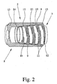
- the helical outflow and cooling channel 6, which is connected in the interior of the housing 2 with the arc chamber 5 is realized in the overvoltage protection device 1 according to the invention characterized in that the housing 2 has a first, inner housing part 7 and a second, outer housing part 8, wherein the intermediate space between the two housing parts 7, 8 forms the outflow and cooling channel 6.
- the inner housing part 7 has an external thread 9 and the outer housing part 8 has a corresponding internal thread 10, so that the inner housing part 7 in FIG shown - fully assembled state is screwed into the outer housing part 8. Due to the helical design of the outflow and cooling channel 6, this has a length which is substantially greater than the length of the housing 2 of the overvoltage protection device 1. As a result, a high braking effect of the hot plasma is achieved within the outflow and cooling channel 6, so that the outflow and cooling channel 6 may have a relatively large cross-section, without the risk that by the out of the Overvoltage protection device 1 escaping gas destroys neighboring plant components or persons are injured.
- the external thread 9 of the inner housing part 7 is partially interrupted, so that between the inner housing part 7 and the outer housing part 8 a plurality of chambers 11 are formed.
- the internal thread 10 of the outer housing part 8 alternatively or additionally have corresponding thread-free sections.
- the housing 2 offers the possibility of the two housing parts 7, 8 with their corresponding threads 9, 10 to be screwed together over a maximum length, whereby the compressive strength of the housing 2 is increased in the axial direction
- the first, inner housing part 7 has a substantially conical outer periphery
- the second, outer housing part 8 has a corresponding conical inner periphery, so that the screw connection between the inner housing part 7 and the outer housing part 8 is designed to be conical overall.
- the inner housing part 7 and the outer housing part 8 at their opposite ends 12, 13 each have the maximum wall thickness, while the wall thickness of the inner housing part 7 and the outer housing part.
- the two housing parts 7, 8 tapered towards the other end 14 and 15, respectively.
- Fig. 1 From Fig. 1 it can be seen that the housing interior is lined with insulating material 16, wherein the configuration of the insulating material 16, which may be for example a thermoplastic, the dimensions of the arc combustion chamber 5 and the connecting channel of the arc combustion chamber 5 to the outflow and cooling channel 6 set réelle-
- the overvoltage protection device shown in Fig. 1 1 an ignition element 17 and an ignition electrode 18, which together serve as a starting aid and by the response voltage of the overvoltage protection device 1 - possibly together with an ignition switch - can be set to the desired value.
- an electrode holder 19 For electrical contacting of the arranged inside the housing 2 first electrode 3, an electrode holder 19 is provided, which is electrically insulated as well as the electrode 4 by means of an insulating part 20 of the housing 2.
- the electrode holder 19 In contrast to the two electrodes 3, 4, which are usually made of copper-tungsten, the electrode holder 19 consists predominantly of brass.
- the housing 2 By the previously described in detail embodiment of the housing 2, in particular the formation of the two housing parts 7 and 8 and the training and use of the screw between the two housing parts 7, 8 as outflow and cooling channel 6, an overvoltage protection device 1 is set to adjournment at the occurrence of an undesirable network follow current after the actual discharge process and a renewed ignition of the breakdown spark gap is more reliably prevented, the housing 2 also has a very high compressive strength.
Landscapes
- Emergency Protection Circuit Devices (AREA)
Applications Claiming Priority (1)
| Application Number | Priority Date | Filing Date | Title |
|---|---|---|---|
| DE202004020260U DE202004020260U1 (de) | 2004-12-28 | 2004-12-28 | Überspannungsschutzeinrichtung |
Publications (3)
| Publication Number | Publication Date |
|---|---|
| EP1677398A2 true EP1677398A2 (fr) | 2006-07-05 |
| EP1677398A3 EP1677398A3 (fr) | 2009-10-21 |
| EP1677398B1 EP1677398B1 (fr) | 2012-02-08 |
Family
ID=34223933
Family Applications (1)
| Application Number | Title | Priority Date | Filing Date |
|---|---|---|---|
| EP05027579A Expired - Lifetime EP1677398B1 (fr) | 2004-12-28 | 2005-12-16 | Dispositif dérivateur de surtensions |
Country Status (5)
| Country | Link |
|---|---|
| US (1) | US7564668B2 (fr) |
| EP (1) | EP1677398B1 (fr) |
| CN (1) | CN1797878B (fr) |
| DE (1) | DE202004020260U1 (fr) |
| ES (1) | ES2381114T3 (fr) |
Families Citing this family (11)
| Publication number | Priority date | Publication date | Assignee | Title |
|---|---|---|---|---|
| DE102005024658B4 (de) * | 2005-05-30 | 2007-02-15 | Dehn + Söhne Gmbh + Co. Kg | Gekapselte, druckfest ausgeführte, nicht hermetisch dichte, rotationssymmetrische Hochleistungsfunkenstrecke |
| DE102006048977B4 (de) * | 2005-05-30 | 2017-02-23 | Dehn + Söhne Gmbh + Co. Kg | Gekapselte, druckfest ausgeführte, nicht hermetisch dichte, rotationssymmetrische Hochleistungsfunkenstrecke |
| EP2080253B1 (fr) * | 2006-10-17 | 2010-10-13 | Dehn + Söhne GmbH + Co. KG | Eclateur a haute puissance, encapsule, resistant a la pression, etanche mais non hermetique et a symetrie de rotation |
| DE102007015931A1 (de) * | 2007-01-04 | 2008-07-10 | Dehn + Söhne Gmbh + Co. Kg | Gekapselte, druckfest ausgeführte, nicht hermetisch dichte, rotationssymmetrische Hochleistungsfunkenstrecke |
| DE102008031113B4 (de) * | 2008-01-08 | 2015-03-05 | Dehn + Söhne Gmbh + Co. Kg | Funkenstreckenanordnung mit mindestens zwei Elektroden |
| US8563888B2 (en) * | 2008-06-11 | 2013-10-22 | General Electric Company | Arc containment device and method |
| DE102009048045B4 (de) * | 2009-10-02 | 2011-06-01 | Phoenix Contact Gmbh & Co. Kg | Überspannungsschutzelement |
| CN102738785B (zh) * | 2011-04-15 | 2015-07-22 | 上海电科电器科技有限公司 | 过电压保护装置的放电模块 |
| CN102738707B (zh) * | 2011-04-15 | 2014-07-23 | 上海电科电器科技有限公司 | 过电压保护装置 |
| DE102014209262B3 (de) * | 2014-05-15 | 2015-10-08 | Phoenix Contact Gmbh & Co. Kg | Funkenstreckenanordnung |
| DE102014209261A1 (de) * | 2014-05-15 | 2015-11-19 | Phoenix Contact Gmbh & Co. Kg | Funkenstreckenanordnung mit verbesserter Kühlung |
Citations (3)
| Publication number | Priority date | Publication date | Assignee | Title |
|---|---|---|---|---|
| DE4141681A1 (de) | 1991-12-17 | 1993-07-29 | Phoenix Contact Gmbh & Co | Ueberspannungsschutzelement |
| DE4402615A1 (de) | 1993-05-31 | 1994-12-08 | Phoenix Contact Gmbh & Co | Überspannungsschutzelement |
| DE19803636A1 (de) | 1998-02-02 | 1999-08-05 | Phoenix Contact Gmbh & Co | Überspannungsschutzsystem |
Family Cites Families (10)
| Publication number | Priority date | Publication date | Assignee | Title |
|---|---|---|---|---|
| US2169110A (en) * | 1938-01-10 | 1939-08-08 | Ralph R Pittman | Repulsion lightning arrester |
| US2545334A (en) * | 1950-06-23 | 1951-03-13 | Gen Electric | Electric circuit interrupter |
| US2768226A (en) * | 1954-08-27 | 1956-10-23 | Inductotherm Corp | Spark-gap converter, induction-heating and melting assembly |
| US2909694A (en) * | 1957-02-26 | 1959-10-20 | Asea Ab | Over-voltage protective device |
| US3064156A (en) * | 1960-12-14 | 1962-11-13 | Ralph R Pittman | Excess-voltage protective device |
| US3300672A (en) * | 1963-05-27 | 1967-01-24 | Neutronic Dev Corp | Spark plug with anti-fouling means and fixed spark gap |
| JPS55102189A (en) * | 1979-01-31 | 1980-08-05 | Tokyo Shibaura Electric Co | Arrester |
| EP0424527A4 (en) * | 1988-11-25 | 1991-08-21 | Vsesojuzny Zaochny Politekhnichesky Institut | Mill roll |
| US5241446A (en) * | 1991-11-22 | 1993-08-31 | Northern Telecom Limited | Overvoltage protector unit for well constructions |
| DE4447567B4 (de) | 1993-05-31 | 2019-01-03 | Phoenix Contact Gmbh & Co. Kg | Überspannungsschutzelement |
-
2004
- 2004-12-28 DE DE202004020260U patent/DE202004020260U1/de not_active Expired - Lifetime
-
2005
- 2005-12-16 ES ES05027579T patent/ES2381114T3/es not_active Expired - Lifetime
- 2005-12-16 EP EP05027579A patent/EP1677398B1/fr not_active Expired - Lifetime
- 2005-12-23 US US11/315,165 patent/US7564668B2/en not_active Expired - Fee Related
- 2005-12-28 CN CN2005101378422A patent/CN1797878B/zh not_active Expired - Fee Related
Patent Citations (3)
| Publication number | Priority date | Publication date | Assignee | Title |
|---|---|---|---|---|
| DE4141681A1 (de) | 1991-12-17 | 1993-07-29 | Phoenix Contact Gmbh & Co | Ueberspannungsschutzelement |
| DE4402615A1 (de) | 1993-05-31 | 1994-12-08 | Phoenix Contact Gmbh & Co | Überspannungsschutzelement |
| DE19803636A1 (de) | 1998-02-02 | 1999-08-05 | Phoenix Contact Gmbh & Co | Überspannungsschutzsystem |
Also Published As
| Publication number | Publication date |
|---|---|
| DE202004020260U1 (de) | 2005-02-24 |
| EP1677398B1 (fr) | 2012-02-08 |
| CN1797878A (zh) | 2006-07-05 |
| EP1677398A3 (fr) | 2009-10-21 |
| US20060139838A1 (en) | 2006-06-29 |
| US7564668B2 (en) | 2009-07-21 |
| CN1797878B (zh) | 2011-11-30 |
| ES2381114T3 (es) | 2012-05-23 |
Similar Documents
| Publication | Publication Date | Title |
|---|---|---|
| DE10338835B4 (de) | Überspannungsschutzeinrichtung | |
| EP2630707B1 (fr) | Éclateur doté de plusieurs éclateurs individuels montés en série et empilés | |
| DE102004009072A1 (de) | Überspannungsschutzelement und Zündelement für ein Überspannungsschutzelement | |
| EP1677398B1 (fr) | Dispositif dérivateur de surtensions | |
| EP1423894B1 (fr) | Dispositif de protection contre les surtensions | |
| EP1692751B1 (fr) | Dispositif de protection contre les surtensions | |
| EP1456921A1 (fr) | Dispositif de protection contre les surtensions | |
| DE10164025B4 (de) | Gekapselter, Netzfolgestrom begrenzender Überspannungsableiter auf Funkenstreckenbasis | |
| DE10146728B4 (de) | Überspannungsschutzeinrichtung | |
| DE102008038486A1 (de) | Überspannungsschutzeinrichtung | |
| DE102007015364B4 (de) | Überspannungsschutzeinrichtung | |
| DE102017114383B4 (de) | Überspannungsableiter | |
| DE102014015611A1 (de) | Überspannungsableiter | |
| DE102014102065B4 (de) | Zündelement zur Verwendung bei einem Überspannungsschutzelement, Überspannungsschutzelement und Verfahren zur Herstellung eines Zündelements | |
| DE102009049579A1 (de) | Überspannungschutzeinrichtung | |
| EP3127199B1 (fr) | Parafoudre | |
| DE102014015610B4 (de) | Überspannungsableiter | |
| DE102014015609B3 (de) | Überspannungsableiter | |
| EP3149814B1 (fr) | Parafoudre | |
| DE10118210B4 (de) | Gekapselter Überspannungsableiter mit einer Funkenstreckenanordnung | |
| EP1419565B1 (fr) | Dechargeur encapsule limitant le courant de suite de secteur con u sous forme d'eclateur a etincelle | |
| DE10212697A1 (de) | Überspannungsschutzeinrichtung | |
| EP2080253B1 (fr) | Eclateur a haute puissance, encapsule, resistant a la pression, etanche mais non hermetique et a symetrie de rotation | |
| DE102006048977B4 (de) | Gekapselte, druckfest ausgeführte, nicht hermetisch dichte, rotationssymmetrische Hochleistungsfunkenstrecke | |
| DE202005008085U1 (de) | Überspannungsschutzeinrichtung |
Legal Events
| Date | Code | Title | Description |
|---|---|---|---|
| PUAI | Public reference made under article 153(3) epc to a published international application that has entered the european phase |
Free format text: ORIGINAL CODE: 0009012 |
|
| AK | Designated contracting states |
Kind code of ref document: A2 Designated state(s): AT BE BG CH CY CZ DE DK EE ES FI FR GB GR HU IE IS IT LI LT LU LV MC NL PL PT RO SE SI SK TR |
|
| AX | Request for extension of the european patent |
Extension state: AL BA HR MK YU |
|
| PUAL | Search report despatched |
Free format text: ORIGINAL CODE: 0009013 |
|
| AK | Designated contracting states |
Kind code of ref document: A3 Designated state(s): AT BE BG CH CY CZ DE DK EE ES FI FR GB GR HU IE IS IT LI LT LU LV MC NL PL PT RO SE SI SK TR |
|
| AX | Request for extension of the european patent |
Extension state: AL BA HR MK YU |
|
| 17P | Request for examination filed |
Effective date: 20100310 |
|
| 17Q | First examination report despatched |
Effective date: 20100526 |
|
| AKX | Designation fees paid |
Designated state(s): DE ES FR IT SE |
|
| GRAP | Despatch of communication of intention to grant a patent |
Free format text: ORIGINAL CODE: EPIDOSNIGR1 |
|
| GRAS | Grant fee paid |
Free format text: ORIGINAL CODE: EPIDOSNIGR3 |
|
| GRAA | (expected) grant |
Free format text: ORIGINAL CODE: 0009210 |
|
| AK | Designated contracting states |
Kind code of ref document: B1 Designated state(s): DE ES FR IT SE |
|
| REG | Reference to a national code |
Ref country code: DE Ref legal event code: R096 Ref document number: 502005012427 Country of ref document: DE Effective date: 20120412 |
|
| REG | Reference to a national code |
Ref country code: SE Ref legal event code: TRGR |
|
| REG | Reference to a national code |
Ref country code: ES Ref legal event code: FG2A Ref document number: 2381114 Country of ref document: ES Kind code of ref document: T3 Effective date: 20120523 |
|
| PLBE | No opposition filed within time limit |
Free format text: ORIGINAL CODE: 0009261 |
|
| STAA | Information on the status of an ep patent application or granted ep patent |
Free format text: STATUS: NO OPPOSITION FILED WITHIN TIME LIMIT |
|
| 26N | No opposition filed |
Effective date: 20121109 |
|
| REG | Reference to a national code |
Ref country code: DE Ref legal event code: R097 Ref document number: 502005012427 Country of ref document: DE Effective date: 20121109 |
|
| REG | Reference to a national code |
Ref country code: FR Ref legal event code: PLFP Year of fee payment: 11 |
|
| PGFP | Annual fee paid to national office [announced via postgrant information from national office to epo] |
Ref country code: ES Payment date: 20151209 Year of fee payment: 11 Ref country code: SE Payment date: 20151221 Year of fee payment: 11 |
|
| REG | Reference to a national code |
Ref country code: FR Ref legal event code: PLFP Year of fee payment: 12 |
|
| PGFP | Annual fee paid to national office [announced via postgrant information from national office to epo] |
Ref country code: IT Payment date: 20161230 Year of fee payment: 12 |
|
| REG | Reference to a national code |
Ref country code: SE Ref legal event code: EUG |
|
| PG25 | Lapsed in a contracting state [announced via postgrant information from national office to epo] |
Ref country code: SE Free format text: LAPSE BECAUSE OF NON-PAYMENT OF DUE FEES Effective date: 20161217 |
|
| REG | Reference to a national code |
Ref country code: FR Ref legal event code: PLFP Year of fee payment: 13 |
|
| PG25 | Lapsed in a contracting state [announced via postgrant information from national office to epo] |
Ref country code: ES Free format text: LAPSE BECAUSE OF NON-PAYMENT OF DUE FEES Effective date: 20161217 |
|
| REG | Reference to a national code |
Ref country code: ES Ref legal event code: FD2A Effective date: 20180628 |
|
| PG25 | Lapsed in a contracting state [announced via postgrant information from national office to epo] |
Ref country code: IT Free format text: LAPSE BECAUSE OF NON-PAYMENT OF DUE FEES Effective date: 20171216 |
|
| PGFP | Annual fee paid to national office [announced via postgrant information from national office to epo] |
Ref country code: FR Payment date: 20191224 Year of fee payment: 15 |
|
| PG25 | Lapsed in a contracting state [announced via postgrant information from national office to epo] |
Ref country code: FR Free format text: LAPSE BECAUSE OF NON-PAYMENT OF DUE FEES Effective date: 20201231 |
|
| P01 | Opt-out of the competence of the unified patent court (upc) registered |
Effective date: 20230424 |
|
| PGFP | Annual fee paid to national office [announced via postgrant information from national office to epo] |
Ref country code: DE Payment date: 20250226 Year of fee payment: 20 |
|
| REG | Reference to a national code |
Ref country code: DE Ref legal event code: R071 Ref document number: 502005012427 Country of ref document: DE |