EP1679209B1 - Befestigungtseinrichtung für Stabilisatoren - Google Patents
Befestigungtseinrichtung für Stabilisatoren Download PDFInfo
- Publication number
- EP1679209B1 EP1679209B1 EP06300019A EP06300019A EP1679209B1 EP 1679209 B1 EP1679209 B1 EP 1679209B1 EP 06300019 A EP06300019 A EP 06300019A EP 06300019 A EP06300019 A EP 06300019A EP 1679209 B1 EP1679209 B1 EP 1679209B1
- Authority
- EP
- European Patent Office
- Prior art keywords
- bar
- stabilizer bar
- main stabilizer
- vehicle
- torsion bar
- Prior art date
- Legal status (The legal status is an assumption and is not a legal conclusion. Google has not performed a legal analysis and makes no representation as to the accuracy of the status listed.)
- Expired - Lifetime
Links
Images

Classifications
-
- B—PERFORMING OPERATIONS; TRANSPORTING
- B60—VEHICLES IN GENERAL
- B60G—VEHICLE SUSPENSION ARRANGEMENTS
- B60G21/00—Interconnection systems for two or more resiliently-suspended wheels, e.g. for stabilising a vehicle body with respect to acceleration, deceleration or centrifugal forces
- B60G21/02—Interconnection systems for two or more resiliently-suspended wheels, e.g. for stabilising a vehicle body with respect to acceleration, deceleration or centrifugal forces permanently interconnected
- B60G21/04—Interconnection systems for two or more resiliently-suspended wheels, e.g. for stabilising a vehicle body with respect to acceleration, deceleration or centrifugal forces permanently interconnected mechanically
- B60G21/05—Interconnection systems for two or more resiliently-suspended wheels, e.g. for stabilising a vehicle body with respect to acceleration, deceleration or centrifugal forces permanently interconnected mechanically between wheels on the same axle but on different sides of the vehicle, i.e. the left and right wheel suspensions being interconnected
- B60G21/055—Stabiliser bars
-
- B—PERFORMING OPERATIONS; TRANSPORTING
- B60—VEHICLES IN GENERAL
- B60G—VEHICLE SUSPENSION ARRANGEMENTS
- B60G2200/00—Indexing codes relating to suspension types
- B60G2200/10—Independent suspensions
- B60G2200/14—Independent suspensions with lateral arms
- B60G2200/144—Independent suspensions with lateral arms with two lateral arms forming a parallelogram
-
- B—PERFORMING OPERATIONS; TRANSPORTING
- B60—VEHICLES IN GENERAL
- B60G—VEHICLE SUSPENSION ARRANGEMENTS
- B60G2202/00—Indexing codes relating to the type of spring, damper or actuator
- B60G2202/10—Type of spring
- B60G2202/13—Torsion spring
- B60G2202/135—Stabiliser bar and/or tube
- B60G2202/1351—Stabiliser bar and/or tube comprising at least two stabiliser bars parallel to each other
-
- B—PERFORMING OPERATIONS; TRANSPORTING
- B60—VEHICLES IN GENERAL
- B60G—VEHICLE SUSPENSION ARRANGEMENTS
- B60G2204/00—Indexing codes related to suspensions per se or to auxiliary parts
- B60G2204/10—Mounting of suspension elements
- B60G2204/12—Mounting of springs or dampers
- B60G2204/122—Mounting of torsion springs
- B60G2204/1222—Middle mounts of stabiliser on vehicle body or chassis
-
- B—PERFORMING OPERATIONS; TRANSPORTING
- B60—VEHICLES IN GENERAL
- B60G—VEHICLE SUSPENSION ARRANGEMENTS
- B60G2204/00—Indexing codes related to suspensions per se or to auxiliary parts
- B60G2204/40—Auxiliary suspension parts; Adjustment of suspensions
- B60G2204/421—Pivoted lever mechanisms for mounting suspension elements, e.g. Watt linkage
-
- B—PERFORMING OPERATIONS; TRANSPORTING
- B60—VEHICLES IN GENERAL
- B60G—VEHICLE SUSPENSION ARRANGEMENTS
- B60G2206/00—Indexing codes related to the manufacturing of suspensions: constructional features, the materials used, procedures or tools
- B60G2206/01—Constructional features of suspension elements, e.g. arms, dampers, springs
- B60G2206/011—Modular constructions
- B60G2206/0114—Independent suspensions on subframes
-
- B—PERFORMING OPERATIONS; TRANSPORTING
- B60—VEHICLES IN GENERAL
- B60G—VEHICLE SUSPENSION ARRANGEMENTS
- B60G2206/00—Indexing codes related to the manufacturing of suspensions: constructional features, the materials used, procedures or tools
- B60G2206/01—Constructional features of suspension elements, e.g. arms, dampers, springs
- B60G2206/60—Subframe construction
- B60G2206/602—Single transverse beam
Definitions
- the present invention relates to a suspension device, preferably, but not exclusively, a front suspension of a motor vehicle, including, in particular, systems for stabilizing the wheels of the vehicle during braking actions or robbery.
- the rocket carriers of the wheels are conventionally linked, by appropriate means, on the one hand, to the cradle of the vehicle train, and, on the other hand, to a set of elastic elements, such as that springs (usually coil springs), fulfilling the function of suspension.
- a set of elastic elements such as that springs (usually coil springs), fulfilling the function of suspension.
- an anti-roll bar is, moreover, linked by appropriate means, on the one hand to said cradle of the train of said vehicle, and, on the other hand, to said elastic elements: this anti-roll bar has, in particular, as its function to maintain the stability of the wheels during braking or steering actions, by offsetting, by its elastic behavior, the imbalances that may then occur.
- the present invention aims to provide a suspension system for a motor vehicle, preferably for a front suspension, wherein said coil springs are removed, while maintaining satisfactory anti-roll performance.
- the invention achieves its goal by means of a suspension device of a motor vehicle comprising, in particular, a main torsion bar connected, by appropriate means, on the one hand to the cradle of the train of said vehicle, and on the other hand , the wheel bearings of the wheels of said vehicle, the central portion of said main torsion bar being placed on said cradle in the substantially transverse direction of said vehicle, characterized in that it comprises at least one complementary bar substantially parallel to said central portion of said main torsion bar.
- Said at least one complementary bar is connected, by appropriate means, at one of its ends, to said main torsion bar, and, at its opposite end, to said cradle of said train.
- the length of said at least one complementary bar is substantially equal to that of said central portion of said main torsion bar.
- said appropriate connecting element between said at least one complementary bar and said main torsion bar allows the rotation of said at least one complementary bar integrally with said main torsion bar.
- two complementary bars are adjoined to said main torsion bar.
- T, L, V an orthonormal reference in which the axes T, L, and V respectively represent the transverse, longitudinal, and vertical directions of a motor vehicle.
- the cradle 1 of a train (preferably the front axle) of a motor vehicle is connected, at one of its ends in the transverse direction T of said vehicle, to a wheel support element (or “carrier”). 2) by means of at least one arm 3.
- Said rocket 2 is also connected by a suitable element (not shown on the figure 1 ), a substantially helical spring 4, itself linked by a suitable arm 5, to a torsion bar 6, the central portion 6 'is placed substantially parallel to the transverse direction T of said vehicle.
- This torsion bar 6 is also secured to said cradle 1 by a set of appropriate elements 7 (not detailed on the figure 1 ).
- figure 1 has only a knuckle 2 and the elements which are linked to it: a symmetrical arrangement is connected to the opposite transverse end of said cradle 1.
- the torsion bar 6 is mainly composed of said central portion 6 'substantially parallel to said transverse direction T of the vehicle, and at each end of said portion 6', a portion 6 "in a general direction substantially parallel to the longitudinal directions L and vertical V: said parts 6 "allow, in particular, the connection of said torsion bar 6 to said coil springs 4, via said arms 5.
- said coil springs 4 can be troublesome in terms of safety, especially for a front suspension, in the case of a pedestrian impact, said coil springs 4, placed substantially in a direction close to the vertical V, opposing the crushing of the hood of the vehicle.
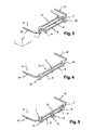
- each complementary bar 8 is placed substantially parallel to the direction of the central portion 6 'of the main torsion bar 6.
- two complementary bars 8 and 8 ' are placed on either side of said central portion 6' of said main torsion bar 6, and each of said complementary bars 8 and 8 'has a length substantially equal to the length of said portion 6 'of said main torsion bar 6, substantially parallel to said transverse direction T.
- each of said complementary bars 8 and 8 ' is, at one of its ends, bound jointly to said central portion 6 'of said main torsion bar 6 via an appropriate element 9 (not shown in the figures) allowing the rotation of said complementary bar 8 or 8' integrally with said central portion 6 'of said main torsion bar 6.
- each of said complementary bars 8 and 8 ' is, moreover, fixed to said cradle 1 by means of an appropriate fitting device 10 (not detailed in the figures).
- said appropriate element 9 is a tab pierced at each of its ends with an orifice, each of said bar 8 or 8 'and central portion 6' of said main torsion bar 6 becoming entangled in each of said orifices.
- the deflections of the wheels are then compensated by the combined stiffness and elasticity of the assembly according to the invention. It then becomes possible to remove the helical springs 4 previously mentioned, thus freeing up space under the hood of the vehicle.
- the respective lengths of said complementary bars 8 and 8 ' are different, and different arrangements of the connection of said complementary bars 8 and 8' to the central portion 6 'of the main torsion bar 6 , on the one hand, and the cradle 1 of the train, on the other hand, can be envisaged.
- each of said complementary bars 8 and 8 ' has a length substantially equal to half the length of the central portion 6' of the main torsion bar 6, whose direction is substantially parallel to said transverse direction T of the vehicle.
- a single element 9 ensures the connection of each of said complementary bars 8 and 8 'with said central portion 6' of said main torsion bar 6, said single element 9 being substantially placed in the middle of said portion 6 'of said bar 6.
- said embedding devices 10 are then substantially placed at each end of said portion 6 'of said main torsion bar 6 and allow, in addition to embedding each of said complementary bars 8 and 8', the embedding of said main torsion bar 6 on said cradle 1, then leading to the removal of said elements 7 previously mentioned.
- said embedding devices 10 are placed in a substantially central position of said portion 6 'of said bar 6, and the connecting elements 9 are situated substantially at each end of said portion 6' of said main torsion bar 6.
Landscapes
- Engineering & Computer Science (AREA)
- Mechanical Engineering (AREA)
- Vehicle Body Suspensions (AREA)
- Springs (AREA)
- Discharge Heating (AREA)
- Steroid Compounds (AREA)
Claims (11)
- Aufhängungsvorrichtung für ein Kraftfahrzeug, die insbesondere eine Hauptdrehstabfeder (6) enthält, die über geeignete Mittel einerseits mit der Wiege (1) des Fahrgestells des Fahrzeugs und andererseits mit den Achsschenkelträgern (2) der Räder des Fahrzeugs verbunden ist, wobei der Mittelteil (6') der Hauptdrehstabfeder (6) an der Wiege (1) in einer im Wesentlichen transversalen Richtung (T) des Fahrzeugs angeordnet ist, wobei die Vorrichtung wenigstens einen Zusatzstab (8) aufweist, der zu dem Mittelteil (6') der Hauptdrehstabfeder (6) im Wesentlichen parallel ist, dadurch gekennzeichnet, dass der wenigstens eine Zusatzstab (8) an einem seiner Enden durch geeignete Mittel (9) mit dem Mittelteil (6') der Hauptdrehstabfeder (6) und an seinem gegenüberliegenden Ende durch eine Befestigungsvorrichtung (10) mit der Wiege (1) verbunden ist.
- Vorrichtung nach Anspruch 1, dadurch gekennzeichnet, dass das geeignete Element (9) die Drehung des wenigstens einen Zusatzstabs (8) auf mit dem Mittelteil (6') der Hauptdrehstabfeder (6) fest verbundene Weise ermöglicht.
- Vorrichtung nach einem der Ansprüche 1 bis 2, dadurch gekennzeichnet, dass die Länge des wenigstens einen Zusatzstabs (8) im Wesentlichen gleich der Länge des Mittelteils (6') der Hauptdrehstabfeder (6) ist.
- Vorrichtung nach einem der Ansprüche 1 bis 3, dadurch gekennzeichnet, dass zwei Zusatzstäbe (8) und (8') mit der Hauptdrehstabfeder (6) zusammengefügt sind.
- Vorrichtung nach einem der Ansprüche 1 bis 4, dadurch gekennzeichnet, dass die Zusatzstäbe (8) und (8') beiderseits des Mittelteils (6') der Hauptdrehstabfeder (6) angeordnet sind.
- Vorrichtung nach einem der Ansprüche 1 bis 2, 4, dadurch gekennzeichnet, dass die Länge jedes der Zusatzstäbe (8) und (8') im Wesentlichen gleich der halben Länge des Mittelteils (6') der Hauptdrehstabfeder (6) ist.
- Vorrichtung nach einem der Ansprüche 1 bis 2, 4, 6, dadurch gekennzeichnet, dass die Zusatzstäbe (8) und (8') mit dem Mittelteil (6') der Hauptdrehstabfeder (6) durch ein einziges geeignetes Element (9) verbunden sind, das im Wesentlichen in der Mitte des Mittelteils (6') der Hauptdrehstabfeder (6) angeordnet ist.
- Vorrichtung nach einem der Ansprüche 1, 2, 4, 6 oder 7, dadurch gekennzeichnet, dass die Vorrichtungen (10) für die Befestigung der Zusatzstäbe (8) und (8') an der Wiege (1) des Fahrgestells im Wesentlichen an den Enden des Mittelteils (6') des Stabs (6) angeordnet sind und gleichzeitig die Befestigung der Zusatzstäbe (8) und (8') und der Hauptdrehstabfeder (6) an der Wiege (1) sicherstellen.
- Vorrichtung nach einem der Ansprüche 1, 2, 4 oder 5, dadurch gekennzeichnet, dass jedes der Elemente (9), die für die Verbindung der Zusatzstäbe (8) und (8') mit dem Mittelteil (6') der Hauptdrehstabfeder (6) geeignet sind, in der Nähe der Enden des Mittelteils (6') der Hauptdrehstabfeder (6) angeordnet ist.
- Vorrichtung nach einem der Ansprüche 1, 2, 4, 5 oder 9, dadurch gekennzeichnet, dass die Vorrichtungen (10) für die Befestigung der Zusatzstäbe (8) und (8') an der Fahrgestellwiege (1) im Wesentlichen an der Mittelposition des Teils (6') der Hauptdrehstabfeder (6) angeordnet sind.
- Kraftfahrzeug, das wenigstens eine Aufhängungsvorrichtung nach einem der Ansprüche 1 bis 10 enthält.
Applications Claiming Priority (1)
| Application Number | Priority Date | Filing Date | Title |
|---|---|---|---|
| FR0550083A FR2880586B1 (fr) | 2005-01-10 | 2005-01-10 | Dispositif de suspension pour barres de torsion |
Publications (2)
| Publication Number | Publication Date |
|---|---|
| EP1679209A1 EP1679209A1 (de) | 2006-07-12 |
| EP1679209B1 true EP1679209B1 (de) | 2008-08-13 |
Family
ID=34954673
Family Applications (1)
| Application Number | Title | Priority Date | Filing Date |
|---|---|---|---|
| EP06300019A Expired - Lifetime EP1679209B1 (de) | 2005-01-10 | 2006-01-10 | Befestigungtseinrichtung für Stabilisatoren |
Country Status (4)
| Country | Link |
|---|---|
| EP (1) | EP1679209B1 (de) |
| AT (1) | ATE404393T1 (de) |
| DE (1) | DE602006002134D1 (de) |
| FR (1) | FR2880586B1 (de) |
Families Citing this family (4)
| Publication number | Priority date | Publication date | Assignee | Title |
|---|---|---|---|---|
| DE102007006589A1 (de) * | 2007-02-09 | 2008-08-14 | Dr. Ing. H.C. F. Porsche Aktiengesellschaft | Kraftfahrzeug mit einem Fahrzeugaufbau und mit einem Fahrwerk |
| DE102007028852A1 (de) * | 2007-06-22 | 2008-12-24 | Bayerische Motoren Werke Aktiengesellschaft | Radaufhängung für ein Kraftfahrzeug |
| EP2311670B1 (de) * | 2009-10-15 | 2012-08-15 | Volvo Car Corporation | Aufhängungssystem |
| DE102016005930B4 (de) * | 2016-05-14 | 2021-10-07 | Audi Ag | Achsanordnung für ein zweispuriges Kraftfahrzeug |
Family Cites Families (6)
| Publication number | Priority date | Publication date | Assignee | Title |
|---|---|---|---|---|
| FR1320822A (fr) * | 1962-01-29 | 1963-03-15 | Renault | Perfectionnements aux suspensions de véhicules par barres de torsion transversales |
| US3733087A (en) * | 1970-12-21 | 1973-05-15 | Ford Motor Co | Independent suspension system for a motor vehicle |
| FR2560828B1 (fr) * | 1984-03-08 | 1988-08-05 | Aerospatiale | Suspension a bras oscillants pour un train de deux roues d'un vehicule et ensemble de tubes paralleles pour une telle suspension |
| US5161818A (en) * | 1989-07-25 | 1992-11-10 | Kopieczek Anthony M J | Lateral compound torsion suspension |
| FR2794689A1 (fr) * | 1999-06-10 | 2000-12-15 | Peugeot Citroen Automobiles Sa | Suspension pour train de roues de vehicules |
| FR2834936B1 (fr) * | 2002-01-22 | 2004-02-27 | Drom Suc | Dispositif de stabilisation de la caisse d'un vehicule routier a moteur, equipe de roues laterales supportees aux extremites d'un essieu |
-
2005
- 2005-01-10 FR FR0550083A patent/FR2880586B1/fr not_active Expired - Fee Related
-
2006
- 2006-01-10 AT AT06300019T patent/ATE404393T1/de not_active IP Right Cessation
- 2006-01-10 DE DE602006002134T patent/DE602006002134D1/de not_active Expired - Lifetime
- 2006-01-10 EP EP06300019A patent/EP1679209B1/de not_active Expired - Lifetime
Also Published As
| Publication number | Publication date |
|---|---|
| FR2880586A1 (fr) | 2006-07-14 |
| DE602006002134D1 (de) | 2008-09-25 |
| FR2880586B1 (fr) | 2013-02-15 |
| ATE404393T1 (de) | 2008-08-15 |
| EP1679209A1 (de) | 2006-07-12 |
Similar Documents
| Publication | Publication Date | Title |
|---|---|---|
| EP1883574B1 (de) | Hintergabel für ein fahrrad | |
| FR2462283A1 (fr) | Suspension a essieu rigide pour vehicules automobiles, assurant un confort analogue aux dispositifs a roues independantes | |
| WO2016166432A1 (fr) | Ensemble de train arriere roulant integrant un moteur semi-porteur pour vehicule automobile | |
| EP1679209A1 (de) | Befestigungtseinrichtung für Stabilisatoren | |
| WO2011023871A1 (fr) | Vehicule comportant un ensemble ressort amortisseur | |
| WO2015092174A1 (fr) | Train de suspension pour véhicule automobile, rotule de liaison pour le train et procédé de montage correspondant | |
| FR3012371A1 (fr) | Combine de suspension comportant un ressort et un amortisseur integre, travaillant en traction | |
| EP1673244A2 (de) | Kraftfahrzeuglenkachse | |
| FR3067299A1 (fr) | Biellette de reprise de couple pour vehicule automobile comportant des butees integrees en cas de choc | |
| EP2168789B1 (de) | Flexible Hinterachse mit Hebel und hohlem Querträger und entsprechendes Fahrzeug | |
| FR2677930A1 (fr) | Dispositif pilote de liaison elastique assurant des rigidites differenciees par chambre tubulaire piezo-raidie. | |
| FR3046570A1 (fr) | Systeme de suspension a barre anti-devers d'un vehicule | |
| FR2793736A1 (fr) | Essieu arriere a traverse deformable avec amortisseur et ressort separes | |
| WO1998006620A1 (fr) | Perfectionnement pour chassis de vehicule | |
| EP0649764A1 (de) | Hinterachsenaufhängung für ein Kraftfahrzeug | |
| EP3077226A1 (de) | Aufhängungsarm für ein kraftfahrzeug zur absorption eines seitenaufpralls | |
| EP3386779B1 (de) | Hinterachsanordnung und vorrichtung zur sicherung davon | |
| WO2013110871A2 (fr) | Dispositif de fixation d'un groupe motopropulseur a la caisse d'un vehicule a moyen de liaison anti-couple | |
| FR2991917A1 (fr) | Train arriere pour vehicule automobile comprenant une lame transversale comportant une largeur importante | |
| FR2909932A1 (fr) | Agencement pour la suspension d'un essieu arriere de vehicule automobile | |
| FR2710583A1 (fr) | Train avant pour véhicule automobile. | |
| FR2832098A1 (fr) | Train arriere a essieu multibras et ressort lame | |
| FR3012385A1 (fr) | Siege escamotable anti deversement | |
| WO2012175844A1 (fr) | Bras de suspension de vehicule | |
| FR2874859A1 (fr) | Dispositif anti-devers de vehicule automobile |
Legal Events
| Date | Code | Title | Description |
|---|---|---|---|
| PUAI | Public reference made under article 153(3) epc to a published international application that has entered the european phase |
Free format text: ORIGINAL CODE: 0009012 |
|
| AK | Designated contracting states |
Kind code of ref document: A1 Designated state(s): AT BE BG CH CY CZ DE DK EE ES FI FR GB GR HU IE IS IT LI LT LU LV MC NL PL PT RO SE SI SK TR |
|
| AX | Request for extension of the european patent |
Extension state: AL BA HR MK YU |
|
| 17P | Request for examination filed |
Effective date: 20061124 |
|
| 17Q | First examination report despatched |
Effective date: 20070111 |
|
| AKX | Designation fees paid |
Designated state(s): AT BE BG CH CY CZ DE DK EE ES FI FR GB GR HU IE IS IT LI LT LU LV MC NL PL PT RO SE SI SK TR |
|
| GRAP | Despatch of communication of intention to grant a patent |
Free format text: ORIGINAL CODE: EPIDOSNIGR1 |
|
| GRAS | Grant fee paid |
Free format text: ORIGINAL CODE: EPIDOSNIGR3 |
|
| GRAA | (expected) grant |
Free format text: ORIGINAL CODE: 0009210 |
|
| AK | Designated contracting states |
Kind code of ref document: B1 Designated state(s): AT BE BG CH CY CZ DE DK EE ES FI FR GB GR HU IE IS IT LI LT LU LV MC NL PL PT RO SE SI SK TR |
|
| REG | Reference to a national code |
Ref country code: GB Ref legal event code: FG4D Free format text: NOT ENGLISH |
|
| REG | Reference to a national code |
Ref country code: CH Ref legal event code: EP |
|
| REG | Reference to a national code |
Ref country code: IE Ref legal event code: FG4D Free format text: LANGUAGE OF EP DOCUMENT: FRENCH |
|
| REF | Corresponds to: |
Ref document number: 602006002134 Country of ref document: DE Date of ref document: 20080925 Kind code of ref document: P |
|
| PG25 | Lapsed in a contracting state [announced via postgrant information from national office to epo] |
Ref country code: IS Free format text: LAPSE BECAUSE OF FAILURE TO SUBMIT A TRANSLATION OF THE DESCRIPTION OR TO PAY THE FEE WITHIN THE PRESCRIBED TIME-LIMIT Effective date: 20081213 Ref country code: NL Free format text: LAPSE BECAUSE OF FAILURE TO SUBMIT A TRANSLATION OF THE DESCRIPTION OR TO PAY THE FEE WITHIN THE PRESCRIBED TIME-LIMIT Effective date: 20080813 Ref country code: LT Free format text: LAPSE BECAUSE OF FAILURE TO SUBMIT A TRANSLATION OF THE DESCRIPTION OR TO PAY THE FEE WITHIN THE PRESCRIBED TIME-LIMIT Effective date: 20080813 |
|
| PG25 | Lapsed in a contracting state [announced via postgrant information from national office to epo] |
Ref country code: LV Free format text: LAPSE BECAUSE OF FAILURE TO SUBMIT A TRANSLATION OF THE DESCRIPTION OR TO PAY THE FEE WITHIN THE PRESCRIBED TIME-LIMIT Effective date: 20080813 Ref country code: AT Free format text: LAPSE BECAUSE OF FAILURE TO SUBMIT A TRANSLATION OF THE DESCRIPTION OR TO PAY THE FEE WITHIN THE PRESCRIBED TIME-LIMIT Effective date: 20080813 Ref country code: SI Free format text: LAPSE BECAUSE OF FAILURE TO SUBMIT A TRANSLATION OF THE DESCRIPTION OR TO PAY THE FEE WITHIN THE PRESCRIBED TIME-LIMIT Effective date: 20080813 Ref country code: ES Free format text: LAPSE BECAUSE OF FAILURE TO SUBMIT A TRANSLATION OF THE DESCRIPTION OR TO PAY THE FEE WITHIN THE PRESCRIBED TIME-LIMIT Effective date: 20081124 Ref country code: FI Free format text: LAPSE BECAUSE OF FAILURE TO SUBMIT A TRANSLATION OF THE DESCRIPTION OR TO PAY THE FEE WITHIN THE PRESCRIBED TIME-LIMIT Effective date: 20080813 |
|
| REG | Reference to a national code |
Ref country code: IE Ref legal event code: FD4D |
|
| PG25 | Lapsed in a contracting state [announced via postgrant information from national office to epo] |
Ref country code: BG Free format text: LAPSE BECAUSE OF FAILURE TO SUBMIT A TRANSLATION OF THE DESCRIPTION OR TO PAY THE FEE WITHIN THE PRESCRIBED TIME-LIMIT Effective date: 20081113 Ref country code: DK Free format text: LAPSE BECAUSE OF FAILURE TO SUBMIT A TRANSLATION OF THE DESCRIPTION OR TO PAY THE FEE WITHIN THE PRESCRIBED TIME-LIMIT Effective date: 20080813 Ref country code: IE Free format text: LAPSE BECAUSE OF FAILURE TO SUBMIT A TRANSLATION OF THE DESCRIPTION OR TO PAY THE FEE WITHIN THE PRESCRIBED TIME-LIMIT Effective date: 20080813 |
|
| PG25 | Lapsed in a contracting state [announced via postgrant information from national office to epo] |
Ref country code: RO Free format text: LAPSE BECAUSE OF FAILURE TO SUBMIT A TRANSLATION OF THE DESCRIPTION OR TO PAY THE FEE WITHIN THE PRESCRIBED TIME-LIMIT Effective date: 20080813 Ref country code: SK Free format text: LAPSE BECAUSE OF FAILURE TO SUBMIT A TRANSLATION OF THE DESCRIPTION OR TO PAY THE FEE WITHIN THE PRESCRIBED TIME-LIMIT Effective date: 20080813 Ref country code: CZ Free format text: LAPSE BECAUSE OF FAILURE TO SUBMIT A TRANSLATION OF THE DESCRIPTION OR TO PAY THE FEE WITHIN THE PRESCRIBED TIME-LIMIT Effective date: 20080813 Ref country code: PT Free format text: LAPSE BECAUSE OF FAILURE TO SUBMIT A TRANSLATION OF THE DESCRIPTION OR TO PAY THE FEE WITHIN THE PRESCRIBED TIME-LIMIT Effective date: 20090113 |
|
| PLBE | No opposition filed within time limit |
Free format text: ORIGINAL CODE: 0009261 |
|
| STAA | Information on the status of an ep patent application or granted ep patent |
Free format text: STATUS: NO OPPOSITION FILED WITHIN TIME LIMIT |
|
| 26N | No opposition filed |
Effective date: 20090514 |
|
| PG25 | Lapsed in a contracting state [announced via postgrant information from national office to epo] |
Ref country code: EE Free format text: LAPSE BECAUSE OF FAILURE TO SUBMIT A TRANSLATION OF THE DESCRIPTION OR TO PAY THE FEE WITHIN THE PRESCRIBED TIME-LIMIT Effective date: 20080813 |
|
| PG25 | Lapsed in a contracting state [announced via postgrant information from national office to epo] |
Ref country code: MC Free format text: LAPSE BECAUSE OF NON-PAYMENT OF DUE FEES Effective date: 20090131 |
|
| REG | Reference to a national code |
Ref country code: FR Ref legal event code: ST Effective date: 20091030 |
|
| PG25 | Lapsed in a contracting state [announced via postgrant information from national office to epo] |
Ref country code: SE Free format text: LAPSE BECAUSE OF FAILURE TO SUBMIT A TRANSLATION OF THE DESCRIPTION OR TO PAY THE FEE WITHIN THE PRESCRIBED TIME-LIMIT Effective date: 20081113 |
|
| PG25 | Lapsed in a contracting state [announced via postgrant information from national office to epo] |
Ref country code: BE Free format text: LAPSE BECAUSE OF NON-PAYMENT OF DUE FEES Effective date: 20090131 |
|
| PG25 | Lapsed in a contracting state [announced via postgrant information from national office to epo] |
Ref country code: FR Free format text: LAPSE BECAUSE OF NON-PAYMENT OF DUE FEES Effective date: 20090202 |
|
| PG25 | Lapsed in a contracting state [announced via postgrant information from national office to epo] |
Ref country code: PL Free format text: LAPSE BECAUSE OF FAILURE TO SUBMIT A TRANSLATION OF THE DESCRIPTION OR TO PAY THE FEE WITHIN THE PRESCRIBED TIME-LIMIT Effective date: 20080813 |
|
| REG | Reference to a national code |
Ref country code: CH Ref legal event code: PL |
|
| GBPC | Gb: european patent ceased through non-payment of renewal fee |
Effective date: 20100110 |
|
| PG25 | Lapsed in a contracting state [announced via postgrant information from national office to epo] |
Ref country code: LI Free format text: LAPSE BECAUSE OF NON-PAYMENT OF DUE FEES Effective date: 20100131 Ref country code: GR Free format text: LAPSE BECAUSE OF FAILURE TO SUBMIT A TRANSLATION OF THE DESCRIPTION OR TO PAY THE FEE WITHIN THE PRESCRIBED TIME-LIMIT Effective date: 20081114 Ref country code: CH Free format text: LAPSE BECAUSE OF NON-PAYMENT OF DUE FEES Effective date: 20100131 |
|
| PG25 | Lapsed in a contracting state [announced via postgrant information from national office to epo] |
Ref country code: GB Free format text: LAPSE BECAUSE OF NON-PAYMENT OF DUE FEES Effective date: 20100110 |
|
| PG25 | Lapsed in a contracting state [announced via postgrant information from national office to epo] |
Ref country code: LU Free format text: LAPSE BECAUSE OF NON-PAYMENT OF DUE FEES Effective date: 20090110 |
|
| PG25 | Lapsed in a contracting state [announced via postgrant information from national office to epo] |
Ref country code: HU Free format text: LAPSE BECAUSE OF FAILURE TO SUBMIT A TRANSLATION OF THE DESCRIPTION OR TO PAY THE FEE WITHIN THE PRESCRIBED TIME-LIMIT Effective date: 20090214 |
|
| PG25 | Lapsed in a contracting state [announced via postgrant information from national office to epo] |
Ref country code: TR Free format text: LAPSE BECAUSE OF FAILURE TO SUBMIT A TRANSLATION OF THE DESCRIPTION OR TO PAY THE FEE WITHIN THE PRESCRIBED TIME-LIMIT Effective date: 20080813 |
|
| PG25 | Lapsed in a contracting state [announced via postgrant information from national office to epo] |
Ref country code: CY Free format text: LAPSE BECAUSE OF FAILURE TO SUBMIT A TRANSLATION OF THE DESCRIPTION OR TO PAY THE FEE WITHIN THE PRESCRIBED TIME-LIMIT Effective date: 20080813 |
|
| PGFP | Annual fee paid to national office [announced via postgrant information from national office to epo] |
Ref country code: DE Payment date: 20170120 Year of fee payment: 12 |
|
| PGFP | Annual fee paid to national office [announced via postgrant information from national office to epo] |
Ref country code: IT Payment date: 20170124 Year of fee payment: 12 |
|
| REG | Reference to a national code |
Ref country code: DE Ref legal event code: R119 Ref document number: 602006002134 Country of ref document: DE |
|
| PG25 | Lapsed in a contracting state [announced via postgrant information from national office to epo] |
Ref country code: DE Free format text: LAPSE BECAUSE OF NON-PAYMENT OF DUE FEES Effective date: 20180801 |
|
| PG25 | Lapsed in a contracting state [announced via postgrant information from national office to epo] |
Ref country code: IT Free format text: LAPSE BECAUSE OF NON-PAYMENT OF DUE FEES Effective date: 20180110 |