EP1679230A1 - Befestigung für eine Tragvorrichtung auf einem Dachgepäckträger - Google Patents
Befestigung für eine Tragvorrichtung auf einem Dachgepäckträger Download PDFInfo
- Publication number
- EP1679230A1 EP1679230A1 EP06290007A EP06290007A EP1679230A1 EP 1679230 A1 EP1679230 A1 EP 1679230A1 EP 06290007 A EP06290007 A EP 06290007A EP 06290007 A EP06290007 A EP 06290007A EP 1679230 A1 EP1679230 A1 EP 1679230A1
- Authority
- EP
- European Patent Office
- Prior art keywords
- fastening
- flanges
- fixing
- bar
- roof
- Prior art date
- Legal status (The legal status is an assumption and is not a legal conclusion. Google has not performed a legal analysis and makes no representation as to the accuracy of the status listed.)
- Granted
Links
- 230000003993 interaction Effects 0.000 claims description 2
- 208000031968 Cadaver Diseases 0.000 description 3
- 230000000694 effects Effects 0.000 description 2
- 239000007787 solid Substances 0.000 description 2
- 240000008042 Zea mays Species 0.000 description 1
- 230000000712 assembly Effects 0.000 description 1
- 238000000429 assembly Methods 0.000 description 1
- 230000004323 axial length Effects 0.000 description 1
- 229940082150 encore Drugs 0.000 description 1
- 238000002955 isolation Methods 0.000 description 1
- 230000007246 mechanism Effects 0.000 description 1
Images


Classifications
-
- B—PERFORMING OPERATIONS; TRANSPORTING
- B60—VEHICLES IN GENERAL
- B60R—VEHICLES, VEHICLE FITTINGS, OR VEHICLE PARTS, NOT OTHERWISE PROVIDED FOR
- B60R9/00—Supplementary fittings on vehicle exterior for carrying loads, e.g. luggage, sports gear or the like
- B60R9/04—Carriers associated with vehicle roof
- B60R9/045—Carriers being adjustable or transformable, e.g. expansible, collapsible
Definitions
- the invention relates to a fastening device for a carrying accessory, this device allowing in particular to fix a carrying accessory on a roof bar of a motor vehicle.
- the device of the invention makes it possible more particularly to fix a carrying accessory such as a roof box, on any type of roof bar, and this by no longer needing to operate individually each of the brackets, also called -after fixing clamps, the carrying accessory.
- the fastening device is also designed so as to be mounted on the roof bars of a motor vehicle without tools.
- these generally comprise only simple holes allowing the passage of a T-bolt in each of the holes, the screws being fastened individually with a nut. , often incorporated in a knurled knob.
- Carrying accessories made according to these designs or having more specific fastening systems have the disadvantage that their user must intervene on each of the feet to attach the carrying accessory on the roof bars of a vehicle.
- the user is obliged to expose himself to the risks of traffic while he fixes the feet on one side of the bars, or to move the vehicle after have secured the secure side of the bars so as to be able to avoid such risks for work on the other side.
- the object of the invention is to provide a fixing device for mounting easier, if possible also faster, a carrying accessory on the roof bars of a motor vehicle.
- the object of the invention is achieved with a fixing device for fixing a carrying accessory on a roof bar of a motor vehicle, the fixing device comprising a first and a second fixing flange each having a free lower end and an upper end, the fixing flanges being spaced apart from each other and connected to the carrying accessory.
- the fixing device also comprises clamping means allowing, together with the fixing flanges, to fix the device on a roof bar by interaction between the free lower ends of the fixing flanges and the roof bar.
- the fixing device comprises a main body traversed by the first and second fastening flanges, the first and second fastening flanges being connected to one another at their upper ends by a bar of clamping being part of the clamping means and being shaped to respectively secure and disassemble the carrying accessory by varying the distance, or spacing, between the upper ends of the first and second clamps and making Arc-bouter fixing clamps to get their fixing and undo the buttress for disassembly.
- the user of such a fixing device is able to fix the two fastening flanges of a fastening device by a single manipulation or, in general, to fix the flanges of attaching a carrying accessory having two or more fasteners according to the invention, in pairs.
- the device of the invention can be used both on motor vehicles having roof bars arranged in the longitudinal direction of the vehicle than on vehicles having roof bars transverse to this direction.
- the or each fastening device is mounted on the same bar or on two different bars.
- the user of a vehicle on which he wishes to mount is able to orient the two devices comprising these four flanges so that the clamping means are accessible on the same side of the vehicle, for example from a sidewalk along which the vehicle is parked.
- Another advantage of the device of the invention lies in the fact that it can be used for any type of roof bars, regardless of their cross section.
- the fixing device advantageously comprises closing tabs, such tab being associated with each fastening flange so as to surround, and thus enclose, the roof bars by flange assemblies / brackets.
- the fixing device according to the invention can be used both for attaching carrying accessories on solid roof bars and for fixing carrying accessories on roof bars provided with a T-slot.
- the fastening flanges and the closing tabs shaped to surround and thus enclose the roof bars are replaced by two U-shaped flanges and two carriage screws.
- the fastening elements when they are composed of a fastening flange and a closing tab, form a closed loop around the roof bar, when the fastening device is put in place. in place.
- This loop opens by separating the fastening flange and the closing tab which slide through an oblong hole in the base plate of the main body of the fixing device and which thus releases a passage sufficient to remove the fastening device of the roof bar.
- the tightening is done by buttressing each of the fastening elements.
- the clamping bar has a thread pitch much larger than the standard pitch.
- the handling element for example the button shaped to be turned without tools, to travel on the clamping bar a greater distance in the direction of the axis of the thread at each turn of the button, accelerating thus the bracing of the fastening flanges.
- sliders on which the clamps and closing tabs move slide on the wedges provided with slopes, arranged in the main body and thus simultaneously allowing the bracing, quickly reduce the play between the bar roof and fixing clamps.
- the fastening device according to the invention can be integrated into a carrying accessory in two different ways.
- the main body is an integral part of the frame of this portage accessory.
- the functional surfaces shown in the accompanying drawings on the main body are shapes provided directly on said frame.
- the fixing device of the invention is independent and is shaped to slip, for example, in grooves provided for this purpose, made in a lower portion of the carrying accessory.
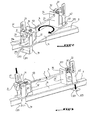
- FIG. 1 shows various elements of a fixing device of the invention made according to a first embodiment and suitable for mounting the device on solid roof bars, as opposed to the second embodiment adapted for mounting the device. of the invention on roof bars provided with a T-slot.
- the fixing device shown in FIG. 1 comprises a main body 1 formed by a base plate 11 and two support elements 12, 13 standing on the base plate 11. Each of the supports 12, 13 is provided with an orifice 14 for housing a clamping bar 5 whose function is described below.
- the fastening device also comprises a first fastening flange 31 and a second fastening flange 32, each having a free lower end referenced respectively 311 and 321 and an upper end referenced respectively 312 and 322.
- the fastening flanges 31, 32 are spaced apart. from each other and each through the base plate 11 in first oblong holes 111, 112 made in the base plate 11 for this purpose.
- the device also comprises closing tabs 41, 42 slidably mounted in second oblong holes 114, 115 (see FIG. 2) made for this purpose in the base plate 11.
- the fixing flanges 31, 32 and the closing tabs 41, 42 are connected to each other by sliders 21, 22 engaged on or near the corresponding end of the clamping bar 5 and, in any case, outside the space defined between the two supports 12, 13.
- the fastening flange 31 and the closing tab 41 are attached to the first slider 21 which is threaded on a first end 51 of the clamping bar 5.
- a first spring 71 is interposed between the first slider 21 and the support 12.
- the fastening flange 32 and the closing tab 42 are attached to the second slider 22 which is threaded onto a second end 52 of the clamping bar 5, with a second spring 72 interposed between the second slider 22 and the support 13.
- the second slider 22 is secured on the end 52 of the clamping bar 5 with appropriate means to prevent the bar 5 can come out of engagement and to prevent rotation of the clamping bar 5 in the second slider 22 .
- the first slider 21, to which are attached the fastening flange 31 and the closing tab 41, is threaded onto the clamping bar 5 so as to allow axial sliding of the slider 21 on the clamping bar 5 when actuating the device of the invention respectively during assembly and disassembly of the device of the invention.
- the clamping bar 5 is provided, at least over part of its axial length, with a thread 53 on which is engaged the knob 6 having a suitable thread.
- the closing tabs 41, 42 are first raised to take the positions shown in FIGS. 1 and 2 in order to release a passage for the bar. Then, the fixing device is positioned obliquely on the roof bar, as shown in FIG. 2. Then, the fixing device is rotated to align it with the roof bar, the latter then entering the recesses respectively defined between the lower ends 311 and 321 and the lower face of the base plate 11. This alignment movement is made possible by an asymmetry of the fastening flanges 31, 32.
- the fixing device of the invention comprises, on the base plate 11, two identical fastening means, but arranged with opposite orientations.
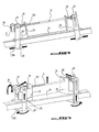
- the knob 6 is rotated on the threaded portion 53 of the clamping bar 5, as indicated in FIG. 5 by a semicircular arrow.
- the button 6 advances on the clamping bar 5 towards the support 12, the sliders 21, 22, and with them the upper ends respectively of the fastening flanges 31, 32 and closure tabs 41, 42, approaching each other and at the same time compressing the return springs 71, 72.
- the advancement of the slide 21 on the clamping bar 5 grants the fixing flanges 31, 32 and the closing tabs 41, 42, which are in pivotal connection with the slides 21, 22, the up and down movements indicated by the arrows of Figure 5.
- the button 6 is loosened.
- the fastening device then automatically returns to its pre-tightening configuration thanks to the return springs 71, 72.
- the fixing device comprises a main body 1 comprising a base plate 11 and supports 12, 13, as well as a first fixing flange and a second fixing flange for each opposite ends of the base plate with, for each attachment flange, a free lower end and an upper end.
- the fixing device according to the second embodiment, shown in FIG. 7, is intended to fix a carrying accessory on a roof bar having a T-slot.
- This device has the same general structure as that according to the first embodiment of the invention. realization, but differs from the latter by the form and type of engagement of the fixing flanges and in particular their free lower ends.
- the fastening flanges of the fastening device according to the second embodiment are referenced, identically for the first and the second fastening flange, 900 for the entire flange.
- Each of these flanges 900 comprises a U-shaped flange 901, and a part made of T comprising a rod 902 and a head 903.
- Each of the attachment flanges 900 is pivotally mounted on a slide 904 threaded onto a clamping bar 5 shaped to respectively secure and dismount the carrying accessory by varying the space between upper ends 905 of the fastening flanges 900 and thus making the fastening flanges 900 snap.
- the clamping bar is at least partially provided with a thread 53 and has a first end 51 on which is engaged a handling element 6 such as a knurled knob, and a second end 52 secured to a second slider 22 to which is attached pivoting one of the two fastening flanges, the other fastening flange being attached to a first slider 904 threaded onto the clamping bar 5.
- a handling element 6 such as a knurled knob
- fastening flanges 900 In particular that they are made in three parts as shown in Figure 7 or that they are made in one piece, the essential is that they comprise a T-head forming the lower end of the fastening flange.
- the lower T-ends When attaching a carrying accessory to a roof bar with a T-slot, the lower T-ends are first slid into the groove of the roof bar. To tighten the assembly and in particular to bend the fastening flanges, one proceeds as described above for the fastening device according to the first embodiment. It is the same for the dismantling of the fixing device.
Landscapes
- Engineering & Computer Science (AREA)
- Mechanical Engineering (AREA)
- Fittings On The Vehicle Exterior For Carrying Loads, And Devices For Holding Or Mounting Articles (AREA)
- Diaphragms For Electromechanical Transducers (AREA)
- Jellies, Jams, And Syrups (AREA)
- Automobile Manufacture Line, Endless Track Vehicle, Trailer (AREA)
- Load-Engaging Elements For Cranes (AREA)
Applications Claiming Priority (1)
| Application Number | Priority Date | Filing Date | Title |
|---|---|---|---|
| FR0500113A FR2880317B1 (fr) | 2005-01-06 | 2005-01-06 | Dispositif de fixation pour accessoire de portage |
Publications (2)
| Publication Number | Publication Date |
|---|---|
| EP1679230A1 true EP1679230A1 (de) | 2006-07-12 |
| EP1679230B1 EP1679230B1 (de) | 2008-11-12 |
Family
ID=34953643
Family Applications (1)
| Application Number | Title | Priority Date | Filing Date |
|---|---|---|---|
| EP06290007A Expired - Lifetime EP1679230B1 (de) | 2005-01-06 | 2006-01-04 | Befestigung für eine Tragvorrichtung auf einem Dachgepäckträger |
Country Status (4)
| Country | Link |
|---|---|
| EP (1) | EP1679230B1 (de) |
| AT (1) | ATE413987T1 (de) |
| DE (1) | DE602006003572D1 (de) |
| FR (1) | FR2880317B1 (de) |
Families Citing this family (1)
| Publication number | Priority date | Publication date | Assignee | Title |
|---|---|---|---|---|
| DE102008058006B3 (de) * | 2008-11-19 | 2010-08-26 | SORTIMO INTERNATIONAL AUSRÜSTUNGSSYSTEME FÜR SERVICEFAHRZEUGE GmbH | Gepäckbefestigungseinrichtung mit Verzurrmechanismus |
Citations (1)
| Publication number | Priority date | Publication date | Assignee | Title |
|---|---|---|---|---|
| WO2000076808A1 (en) * | 1999-06-16 | 2000-12-21 | Calix Ab | Device for securing a load bearing element |
-
2005
- 2005-01-06 FR FR0500113A patent/FR2880317B1/fr not_active Expired - Fee Related
-
2006
- 2006-01-04 AT AT06290007T patent/ATE413987T1/de not_active IP Right Cessation
- 2006-01-04 DE DE602006003572T patent/DE602006003572D1/de not_active Expired - Fee Related
- 2006-01-04 EP EP06290007A patent/EP1679230B1/de not_active Expired - Lifetime
Patent Citations (1)
| Publication number | Priority date | Publication date | Assignee | Title |
|---|---|---|---|---|
| WO2000076808A1 (en) * | 1999-06-16 | 2000-12-21 | Calix Ab | Device for securing a load bearing element |
Also Published As
| Publication number | Publication date |
|---|---|
| DE602006003572D1 (de) | 2008-12-24 |
| ATE413987T1 (de) | 2008-11-15 |
| FR2880317A1 (fr) | 2006-07-07 |
| FR2880317B1 (fr) | 2007-03-16 |
| EP1679230B1 (de) | 2008-11-12 |
Similar Documents
| Publication | Publication Date | Title |
|---|---|---|
| FR2736019A1 (fr) | Dispositif de fixation pour emploi avec un porte-bagages de vehicule | |
| EP2636815B1 (de) | Bügel zum Befestigen eines Handlaufs eines Geländers auf einem Pfosten | |
| FR2829082A1 (fr) | Dispositif formant porte-velos pour le transport d'au moins une bicyclette transversalement a l'arriere d'un vehicule automobile | |
| EP4129764A1 (de) | Fahrzeug mit modulierbaren und manipulationssicheren dachgepäckträgern | |
| FR3000718A1 (fr) | Dispositif de pliage pour dispositif de porte-bicyclettes | |
| EP1679230B1 (de) | Befestigung für eine Tragvorrichtung auf einem Dachgepäckträger | |
| EP1338474B1 (de) | Kraftfahrzeug-Dachkoffer-Befestigungsvorrichtung an einem Gestell | |
| FR3098166A1 (fr) | Dispositif de montage amovible d’un module de coussin gonflable sur un volant | |
| EP1728686B1 (de) | Dachlastträger mit einstellbarer Querstange | |
| FR3008896A1 (fr) | Systeme de fixation reglable pour planche de glisse et planche equipee d’un tel systeme | |
| EP1512442B1 (de) | Snowboardbindung | |
| EP0567050A1 (de) | Schutterstütze für eine Violine | |
| EP1076003B1 (de) | Vorrichtung zur Befestigung eines Gegenstandes, insbesondere einer Tasche, auf einem Motorradtank | |
| CA2472898A1 (fr) | Siege pour enfant comprenant des moyens pour tendre une sangle de ceinture de securite | |
| EP2085266B1 (de) | Innerer Dachgepäckträger | |
| FR2845658A1 (fr) | Garde-boue extensible pour bicyclette. | |
| EP3124328B1 (de) | Dachlastenträger | |
| WO2003080395A1 (fr) | Porte-velos rapportable a un vehicule | |
| FR2820381A1 (fr) | Dispositif pour le transport d'au moins un objet transversalement a l'arriere d'un vehicule automobile | |
| EP2551156B1 (de) | PC-Halter, der an Autositze angepasst werden kann | |
| EP3623260B1 (de) | Positionsverriegelungsvorrichtung einer lenksäule, und entsprechende lenksäuleneinheit | |
| FR2997356A1 (fr) | Dispositif de fixation pour fixer un cadre de bicyclette a un porte-bicyclettes | |
| FR2644127A1 (fr) | Siege pour enfant destine a etre monte sur des cycles a moteur ou non | |
| FR2836562A1 (fr) | Barrette decorative amovible destnee a etre fixee sur un support et utilisation | |
| FR2509249A1 (fr) | Pedale de bicyclette permettant l'accrochage d'une chaussure en position prereglee |
Legal Events
| Date | Code | Title | Description |
|---|---|---|---|
| PUAI | Public reference made under article 153(3) epc to a published international application that has entered the european phase |
Free format text: ORIGINAL CODE: 0009012 |
|
| AK | Designated contracting states |
Kind code of ref document: A1 Designated state(s): AT BE BG CH CY CZ DE DK EE ES FI FR GB GR HU IE IS IT LI LT LU LV MC NL PL PT RO SE SI SK TR |
|
| AX | Request for extension of the european patent |
Extension state: AL BA HR MK YU |
|
| 17P | Request for examination filed |
Effective date: 20061108 |
|
| 17Q | First examination report despatched |
Effective date: 20061222 |
|
| AKX | Designation fees paid |
Designated state(s): AT BE BG CH CY CZ DE DK EE ES FI FR GB GR HU IE IS IT LI LT LU LV MC NL PL PT RO SE SI SK TR |
|
| GRAP | Despatch of communication of intention to grant a patent |
Free format text: ORIGINAL CODE: EPIDOSNIGR1 |
|
| GRAS | Grant fee paid |
Free format text: ORIGINAL CODE: EPIDOSNIGR3 |
|
| GRAA | (expected) grant |
Free format text: ORIGINAL CODE: 0009210 |
|
| AK | Designated contracting states |
Kind code of ref document: B1 Designated state(s): AT BE BG CH CY CZ DE DK EE ES FI FR GB GR HU IE IS IT LI LT LU LV MC NL PL PT RO SE SI SK TR |
|
| REG | Reference to a national code |
Ref country code: GB Ref legal event code: FG4D Free format text: NOT ENGLISH |
|
| REG | Reference to a national code |
Ref country code: CH Ref legal event code: EP |
|
| REG | Reference to a national code |
Ref country code: IE Ref legal event code: FG4D Free format text: LANGUAGE OF EP DOCUMENT: FRENCH |
|
| REF | Corresponds to: |
Ref document number: 602006003572 Country of ref document: DE Date of ref document: 20081224 Kind code of ref document: P |
|
| LTIE | Lt: invalidation of european patent or patent extension |
Effective date: 20081112 |
|
| PG25 | Lapsed in a contracting state [announced via postgrant information from national office to epo] |
Ref country code: LT Free format text: LAPSE BECAUSE OF FAILURE TO SUBMIT A TRANSLATION OF THE DESCRIPTION OR TO PAY THE FEE WITHIN THE PRESCRIBED TIME-LIMIT Effective date: 20081112 Ref country code: ES Free format text: LAPSE BECAUSE OF FAILURE TO SUBMIT A TRANSLATION OF THE DESCRIPTION OR TO PAY THE FEE WITHIN THE PRESCRIBED TIME-LIMIT Effective date: 20090223 Ref country code: AT Free format text: LAPSE BECAUSE OF FAILURE TO SUBMIT A TRANSLATION OF THE DESCRIPTION OR TO PAY THE FEE WITHIN THE PRESCRIBED TIME-LIMIT Effective date: 20081112 |
|
| NLV1 | Nl: lapsed or annulled due to failure to fulfill the requirements of art. 29p and 29m of the patents act | ||
| PG25 | Lapsed in a contracting state [announced via postgrant information from national office to epo] |
Ref country code: NL Free format text: LAPSE BECAUSE OF FAILURE TO SUBMIT A TRANSLATION OF THE DESCRIPTION OR TO PAY THE FEE WITHIN THE PRESCRIBED TIME-LIMIT Effective date: 20081112 Ref country code: PL Free format text: LAPSE BECAUSE OF FAILURE TO SUBMIT A TRANSLATION OF THE DESCRIPTION OR TO PAY THE FEE WITHIN THE PRESCRIBED TIME-LIMIT Effective date: 20081112 Ref country code: LV Free format text: LAPSE BECAUSE OF FAILURE TO SUBMIT A TRANSLATION OF THE DESCRIPTION OR TO PAY THE FEE WITHIN THE PRESCRIBED TIME-LIMIT Effective date: 20081112 Ref country code: FI Free format text: LAPSE BECAUSE OF FAILURE TO SUBMIT A TRANSLATION OF THE DESCRIPTION OR TO PAY THE FEE WITHIN THE PRESCRIBED TIME-LIMIT Effective date: 20081112 Ref country code: SI Free format text: LAPSE BECAUSE OF FAILURE TO SUBMIT A TRANSLATION OF THE DESCRIPTION OR TO PAY THE FEE WITHIN THE PRESCRIBED TIME-LIMIT Effective date: 20081112 Ref country code: IS Free format text: LAPSE BECAUSE OF FAILURE TO SUBMIT A TRANSLATION OF THE DESCRIPTION OR TO PAY THE FEE WITHIN THE PRESCRIBED TIME-LIMIT Effective date: 20090312 |
|
| REG | Reference to a national code |
Ref country code: IE Ref legal event code: FD4D |
|
| PG25 | Lapsed in a contracting state [announced via postgrant information from national office to epo] |
Ref country code: BG Free format text: LAPSE BECAUSE OF FAILURE TO SUBMIT A TRANSLATION OF THE DESCRIPTION OR TO PAY THE FEE WITHIN THE PRESCRIBED TIME-LIMIT Effective date: 20090212 Ref country code: IE Free format text: LAPSE BECAUSE OF FAILURE TO SUBMIT A TRANSLATION OF THE DESCRIPTION OR TO PAY THE FEE WITHIN THE PRESCRIBED TIME-LIMIT Effective date: 20081112 Ref country code: RO Free format text: LAPSE BECAUSE OF FAILURE TO SUBMIT A TRANSLATION OF THE DESCRIPTION OR TO PAY THE FEE WITHIN THE PRESCRIBED TIME-LIMIT Effective date: 20081112 Ref country code: EE Free format text: LAPSE BECAUSE OF FAILURE TO SUBMIT A TRANSLATION OF THE DESCRIPTION OR TO PAY THE FEE WITHIN THE PRESCRIBED TIME-LIMIT Effective date: 20081112 Ref country code: DK Free format text: LAPSE BECAUSE OF FAILURE TO SUBMIT A TRANSLATION OF THE DESCRIPTION OR TO PAY THE FEE WITHIN THE PRESCRIBED TIME-LIMIT Effective date: 20081112 |
|
| PG25 | Lapsed in a contracting state [announced via postgrant information from national office to epo] |
Ref country code: SE Free format text: LAPSE BECAUSE OF FAILURE TO SUBMIT A TRANSLATION OF THE DESCRIPTION OR TO PAY THE FEE WITHIN THE PRESCRIBED TIME-LIMIT Effective date: 20090212 Ref country code: MC Free format text: LAPSE BECAUSE OF NON-PAYMENT OF DUE FEES Effective date: 20090131 Ref country code: CZ Free format text: LAPSE BECAUSE OF FAILURE TO SUBMIT A TRANSLATION OF THE DESCRIPTION OR TO PAY THE FEE WITHIN THE PRESCRIBED TIME-LIMIT Effective date: 20081112 Ref country code: PT Free format text: LAPSE BECAUSE OF FAILURE TO SUBMIT A TRANSLATION OF THE DESCRIPTION OR TO PAY THE FEE WITHIN THE PRESCRIBED TIME-LIMIT Effective date: 20090413 |
|
| PLBE | No opposition filed within time limit |
Free format text: ORIGINAL CODE: 0009261 |
|
| STAA | Information on the status of an ep patent application or granted ep patent |
Free format text: STATUS: NO OPPOSITION FILED WITHIN TIME LIMIT |
|
| PG25 | Lapsed in a contracting state [announced via postgrant information from national office to epo] |
Ref country code: SK Free format text: LAPSE BECAUSE OF FAILURE TO SUBMIT A TRANSLATION OF THE DESCRIPTION OR TO PAY THE FEE WITHIN THE PRESCRIBED TIME-LIMIT Effective date: 20081112 |
|
| 26N | No opposition filed |
Effective date: 20090813 |
|
| PG25 | Lapsed in a contracting state [announced via postgrant information from national office to epo] |
Ref country code: DE Free format text: LAPSE BECAUSE OF NON-PAYMENT OF DUE FEES Effective date: 20090801 |
|
| REG | Reference to a national code |
Ref country code: FR Ref legal event code: ST Effective date: 20091030 |
|
| PG25 | Lapsed in a contracting state [announced via postgrant information from national office to epo] |
Ref country code: BE Free format text: LAPSE BECAUSE OF NON-PAYMENT OF DUE FEES Effective date: 20090131 |
|
| PG25 | Lapsed in a contracting state [announced via postgrant information from national office to epo] |
Ref country code: FR Free format text: LAPSE BECAUSE OF NON-PAYMENT OF DUE FEES Effective date: 20090202 |
|
| REG | Reference to a national code |
Ref country code: CH Ref legal event code: PL |
|
| GBPC | Gb: european patent ceased through non-payment of renewal fee |
Effective date: 20100104 |
|
| PG25 | Lapsed in a contracting state [announced via postgrant information from national office to epo] |
Ref country code: CH Free format text: LAPSE BECAUSE OF NON-PAYMENT OF DUE FEES Effective date: 20100131 Ref country code: LI Free format text: LAPSE BECAUSE OF NON-PAYMENT OF DUE FEES Effective date: 20100131 Ref country code: GR Free format text: LAPSE BECAUSE OF FAILURE TO SUBMIT A TRANSLATION OF THE DESCRIPTION OR TO PAY THE FEE WITHIN THE PRESCRIBED TIME-LIMIT Effective date: 20090213 |
|
| PG25 | Lapsed in a contracting state [announced via postgrant information from national office to epo] |
Ref country code: GB Free format text: LAPSE BECAUSE OF NON-PAYMENT OF DUE FEES Effective date: 20100104 |
|
| PG25 | Lapsed in a contracting state [announced via postgrant information from national office to epo] |
Ref country code: IT Free format text: LAPSE BECAUSE OF FAILURE TO SUBMIT A TRANSLATION OF THE DESCRIPTION OR TO PAY THE FEE WITHIN THE PRESCRIBED TIME-LIMIT Effective date: 20081112 |
|
| PG25 | Lapsed in a contracting state [announced via postgrant information from national office to epo] |
Ref country code: LU Free format text: LAPSE BECAUSE OF NON-PAYMENT OF DUE FEES Effective date: 20090104 |
|
| PG25 | Lapsed in a contracting state [announced via postgrant information from national office to epo] |
Ref country code: HU Free format text: LAPSE BECAUSE OF FAILURE TO SUBMIT A TRANSLATION OF THE DESCRIPTION OR TO PAY THE FEE WITHIN THE PRESCRIBED TIME-LIMIT Effective date: 20090513 |
|
| PG25 | Lapsed in a contracting state [announced via postgrant information from national office to epo] |
Ref country code: TR Free format text: LAPSE BECAUSE OF FAILURE TO SUBMIT A TRANSLATION OF THE DESCRIPTION OR TO PAY THE FEE WITHIN THE PRESCRIBED TIME-LIMIT Effective date: 20081112 |
|
| PG25 | Lapsed in a contracting state [announced via postgrant information from national office to epo] |
Ref country code: CY Free format text: LAPSE BECAUSE OF FAILURE TO SUBMIT A TRANSLATION OF THE DESCRIPTION OR TO PAY THE FEE WITHIN THE PRESCRIBED TIME-LIMIT Effective date: 20081112 |