EP1679698A1 - Appareil, procede et support d'enregistrement d'informations - Google Patents
Appareil, procede et support d'enregistrement d'informations Download PDFInfo
- Publication number
- EP1679698A1 EP1679698A1 EP04788295A EP04788295A EP1679698A1 EP 1679698 A1 EP1679698 A1 EP 1679698A1 EP 04788295 A EP04788295 A EP 04788295A EP 04788295 A EP04788295 A EP 04788295A EP 1679698 A1 EP1679698 A1 EP 1679698A1
- Authority
- EP
- European Patent Office
- Prior art keywords
- recording
- information
- irradiation condition
- recorded
- layer
- Prior art date
- Legal status (The legal status is an assumption and is not a legal conclusion. Google has not performed a legal analysis and makes no representation as to the accuracy of the status listed.)
- Granted
Links
Images






Classifications
-
- G—PHYSICS
- G11—INFORMATION STORAGE
- G11B—INFORMATION STORAGE BASED ON RELATIVE MOVEMENT BETWEEN RECORD CARRIER AND TRANSDUCER
- G11B7/00—Recording or reproducing by optical means, e.g. recording using a thermal beam of optical radiation by modifying optical properties or the physical structure, reproducing using an optical beam at lower power by sensing optical properties; Record carriers therefor
- G11B7/004—Recording, reproducing or erasing methods; Read, write or erase circuits therefor
- G11B7/0045—Recording
-
- G—PHYSICS
- G11—INFORMATION STORAGE
- G11B—INFORMATION STORAGE BASED ON RELATIVE MOVEMENT BETWEEN RECORD CARRIER AND TRANSDUCER
- G11B7/00—Recording or reproducing by optical means, e.g. recording using a thermal beam of optical radiation by modifying optical properties or the physical structure, reproducing using an optical beam at lower power by sensing optical properties; Record carriers therefor
- G11B7/004—Recording, reproducing or erasing methods; Read, write or erase circuits therefor
- G11B7/006—Overwriting
- G11B7/0062—Overwriting strategies, e.g. recording pulse sequences with erasing level used for phase-change media
-
- G—PHYSICS
- G11—INFORMATION STORAGE
- G11B—INFORMATION STORAGE BASED ON RELATIVE MOVEMENT BETWEEN RECORD CARRIER AND TRANSDUCER
- G11B7/00—Recording or reproducing by optical means, e.g. recording using a thermal beam of optical radiation by modifying optical properties or the physical structure, reproducing using an optical beam at lower power by sensing optical properties; Record carriers therefor
- G11B7/12—Heads, e.g. forming of the optical beam spot or modulation of the optical beam
- G11B7/125—Optical beam sources therefor, e.g. laser control circuitry specially adapted for optical storage devices; Modulators, e.g. means for controlling the size or intensity of optical spots or optical traces
- G11B7/126—Circuits, methods or arrangements for laser control or stabilisation
- G11B7/1263—Power control during transducing, e.g. by monitoring
-
- G—PHYSICS
- G11—INFORMATION STORAGE
- G11B—INFORMATION STORAGE BASED ON RELATIVE MOVEMENT BETWEEN RECORD CARRIER AND TRANSDUCER
- G11B7/00—Recording or reproducing by optical means, e.g. recording using a thermal beam of optical radiation by modifying optical properties or the physical structure, reproducing using an optical beam at lower power by sensing optical properties; Record carriers therefor
- G11B2007/0003—Recording, reproducing or erasing systems characterised by the structure or type of the carrier
- G11B2007/0009—Recording, reproducing or erasing systems characterised by the structure or type of the carrier for carriers having data stored in three dimensions, e.g. volume storage
- G11B2007/0013—Recording, reproducing or erasing systems characterised by the structure or type of the carrier for carriers having data stored in three dimensions, e.g. volume storage for carriers having multiple discrete layers
-
- G—PHYSICS
- G11—INFORMATION STORAGE
- G11B—INFORMATION STORAGE BASED ON RELATIVE MOVEMENT BETWEEN RECORD CARRIER AND TRANSDUCER
- G11B7/00—Recording or reproducing by optical means, e.g. recording using a thermal beam of optical radiation by modifying optical properties or the physical structure, reproducing using an optical beam at lower power by sensing optical properties; Record carriers therefor
- G11B7/007—Arrangement of the information on the record carrier, e.g. form of tracks, actual track shape, e.g. wobbled, or cross-section, e.g. v-shaped; Sequential information structures, e.g. sectoring or header formats within a track
- G11B7/00736—Auxiliary data, e.g. lead-in, lead-out, Power Calibration Area [PCA], Burst Cutting Area [BCA], control information
Definitions
- This type of information recording apparatus is constructed to record information by laser light for recording with a pulse width, pulse intensity, a pulse shape, recording strategy, or the like which are preferable (referred to as a "preferable irradiation condition" in this application as occasion demands) in accordance with the recording layer of the information recording medium, such as an optical disc.
- the laser light reaches the other recording layers other than one recording layer located on the front as viewed from the irradiation side of the laser light, through at least one recording layer, and a semitransparent reflective film, an adhesive film, or a middle film, or the like accompanied by the one recording layer.
- the light reflected here is also detected by an optical pickup through the one recording layer or the like.
- an information recording method is an information recording method of recording information onto an information recording medium provided with a plurality of recording layers, by irradiating the information recording medium with laser light for recording, the information recording method provided with a setting process of setting a preferable irradiation condition of the laser light which is preferable to one recording layer in which the information is scheduled to be recorded, out of the plurality of recording layers, for each recording state of another recording layer out of the plurality of recording layers; and an irradiating process of irradiating the one recording layer with the laser light in the set preferable irradiation condition.
- the preferable irradiation condition related to the laser light for recording such as the pulse width, the pulse intensity, the pulse shape, and the recording strategy, generally varies depending on each recording state of the another recording layer.
- the embodiment it is possible to irradiate the laser light in the preferable irradiation condition, regardless of the recording state, which is recorded or unrecorded or the like, of another recording layer, such as the recording layer located on the front as viewed from the irradiation side of the laser light.
- another recording layer such as the recording layer located on the front as viewed from the irradiation side of the laser light.
- the preferable irradiation condition information is recorded in the management information area which is in or near a lead-in area, for example.
- Such preferable irradiation condition information may be recorded as pre-format information, such as a pre-pit, in advance, or may be recorded as the preferable irradiation condition information which is separately generated through the setting operation performed by the setting device.
- the preferable irradiation condition information is read from the management information area by the reading device including an optical pickup or the like, for example. Then, the preferable irradiation condition is set by the setting device, on the basis of the read preferable irradiation condition information.
- the preferable irradiation condition information obtained by using the test writing process which requires a relatively long time and a relatively heavy processing load, is maintained on the information recording apparatus side, to thereby allow the effective use thereof.
- At least one of the plurality of recording layers has a management information area in which preferable irradiation condition information for defining the preferable irradiation condition in only one of (i) a case where the another recording layer is unrecorded and (ii) a case where the another recording layer is recorded, is recorded
- the information recording apparatus is further provided with a third reading device for reading the preferable irradiation condition information from the management information area, and the setting device sets the preferable irradiation condition on the basis of the read preferable irradiation condition information in the one case, and sets the preferable irradiation condition on the basis of (I) the read preferable irradiation condition information and (II) relationship information which indicates a relative relationship between a preferable irradiation defined for the other case and a preferable irradiation condition defined for the one case, in the other case out of the unrecorded case and the recorded case.
- the preferable irradiation condition information is recorded in the management information area which is in or near a lead-in area, for example.
- Such preferable irradiation condition information is defined in only one of (i) the case where the another recording layer is unrecorded and (ii) the case where the another recording layer is recorded.
- the relationship information may be recorded in the management information area together with the preferable irradiation condition information.
- the embodiment of the information recording method of the present invention is an information recording method of recording information onto an information recording medium provided with a plurality of recording layers, by irradiating the information recording medium with laser light for recording, the information recording method provided with: a setting process of setting a preferable irradiation condition of the laser light which is preferable to one recording layer in which the information is scheduled to be recorded, out of the plurality of recording layers, for each recording state of another recording layer out of the plurality of recording layers; and an irradiating process of irradiating the one recording layer with the laser light in the set preferable irradiation condition.
- a first embodiment of the information recording medium of the present invention is an information recording medium provided with a plurality of recording layers to record therein information by irradiating the information recording medium with laser light for recording, wherein at least one of the plurality of recording layers has a management information area in which preferable irradiation condition information is recorded, in which the preferable irradiation condition information is to define a preferable irradiation condition of the laser light which is preferable to one recording layer in which the information is scheduled to be recorded, out of the plurality of recording layers, for each recording state of another recording layer out of the plurality of recording layers.
- At least one of the plurality of recording layers, which are stacked or laminated on one side of a substrate, i.e., which constitute the multilayer type information recording medium, such as a multilayer type or dual layer or multiple layer type optical disc, for example, has the management information area in or near a lead-in area located near the inner circumference.
- the preferable irradiation condition information is recorded, wherein the preferable irradiation condition information is to define the preferable irradiation condition of the laser light for recording, for each recording state of another recording layer out of the plurality of recording layers.
- the preferable irradiation condition information may be recorded from the beginning of the production of the information recording medium, or may be recorded upon subsequent pre-formatting or formatting. Alternatively, before the information is recorded, the value of default may be recorded in the management information area, and then, it may be updated by a non-default value.
- the preferable irradiation condition information may be directly defined, or indirectly defined, for example, by defining it with a coefficient based on one irradiation condition (e.g. the pulse width).
- a second embodiment of the information recording medium of the present invention is an information recording medium, provided with a plurality of recording layers to record therein information by irradiating the information recording medium with laser light for recording, and having a first test writing area in which the information is recorded in another recording layer out of the plurality of recording layers and a second test writing area in which the information is not recorded in the another recording layer, in order to obtain a preferable irradiation condition of the laser light which is preferable to one recording layer in which the information is scheduled to be recorded, out of the plurality of recording layers.
- test writing is performed into the both first and second test writing areas, as occasion demands. For example, the OPC is performed. Then, on the basis of the test writing result, it is possible to irradiate the laser light in the preferable irradiation condition, regardless of the recording state, which is recorded or unrecorded or the like, of another recording layer, such as the recording layer located on the front as viewed from the irradiation side of the laser light. By this, it is possible to record the information in a good condition, onto the multilayer type information recording medium, regardless of its recording state.
- the present invention is not particularly limited to the optical disc having these three areas.
- the lead-in area 101 or the lead-out area 103 does not exist, a data structure explained below can be constructed.
- the lead-in area 101 or the lead-out area 103 may be further segmentized.
- the optical disc 100 in the example is constructed as a two-layer type optical disc in which a plurality of data zones 102 or the like area formed in a laminated structure.
- FIG. 2 is a partially enlarged perspective view showing a recording surface of the optical disc according to the example of the information recording medium of the present invention.
- a first recording layer 107 of a phase change type or of an irreversible change recording type by heat or the like which constitutes an information recording surface is stacked or laminated on (on the lower side of, in FIG. 2) a disc-shaped transparent substrate 106, and a semitransparent reflective film 108 is stacked or laminated thereon (on the lower side in FIG. 2).
- a groove track GT and a land track LT are alternately formed.
- the groove track GT is irradiated with laser light LB through the transparent substrate 106.
- the groove track GT is wobbled with a certain amplitude and at a certain spatial frequency.
- the groove track GT is wobbled, and the cycle of the wobble 109 is set to a predetermined value.
- On the land track LT there is formed an address pit which is referred to as a land pre-pit LP and which indicate pre-format address information.
- the two addressing i.e. the wobble 109 and the land pre-pit LP
- it is possible to obtain information necessary for data recording such as a recording address, disc rotation control during the recording, or generation of a recording clock.
- a second recording layer 207 is formed on (on the lower side of, in FIG. 2) the semitransparent reflective film 108, and a reflective film 208 is formed thereon (on the lower side in FIG. 2).
- the second recording layer 207 is constructed such that the recording and reproduction of a phase change type or of an irreversible change recording type by heat or the like can be performed by irradiating it with the laser light LB through the transparent substrate 106, the first recording layer 107, and the semitransparent reflective film 108, in substantially the same manner of the first recording layer 107.
- the second recording layer 207 and the reflective film 208 may be coated and formed on the transparent substrate 106 on which the first recording layer 107 and the semitransparent reflective film 108 or the like are formed.
- the second recording layer 207 and the reflective film 208 may be bonded or pasted on the transparent substrate 106.
- a transparent middle layer 205 made of a transparent adhesive or the like, between the semitransparent reflective film 108 and the second recording layer 207, as occasion demands, in accordance with the production method.
- the recording / reproduction in the first recording layer 107 or the second recording layer 207 is performed, depending on which recording layer has the focus position of laser light LB.
- the optical disc 100 in the example is not limited to a two-layer single sided type, i.e., a dual layer type, as shown in FIG. 2, but may be one-layer double sided type, i.e., a double sided type, or a two-layer double sided type, i.e., a dual layer double sided type.
- the optical disc 100 in the example is not limited to the optical disc having the two recording layers, as described above, but may be an optical disc of a multilayer type which has three or more layers.
- FIG. 3 is a data structural view conceptually showing an example of the data structure of the optical disc in the example.
- the optical disc 100 has two recording layers, i.e., an L0 layer (i.e. a recording layer corresponding to the first recording layer 107 in FIG. 1 and FIG. 2) and an L1 layer (i.e. a recording layer corresponding to the second recording layer 207 in FIG. 1 and FIG. 2).
- an L0 layer i.e. a recording layer corresponding to the first recording layer 107 in FIG. 1 and FIG. 2
- an L1 layer i.e. a recording layer corresponding to the second recording layer 207 in FIG. 1 and FIG. 2
- the L1 layer is also provided with: a lead-in area 101-1; a data zone 102-1; and a lead-out area 103-1.
- the lead-in area 101-1 is provided with an OPC area 101A-1 and a management information recording area 101B-1.
- the management information recording area 101B-1 in the L1 layer there may be recorded preferable information 101C-1 upon not-recording and ratio or difference information 101D-1 (or preferable information upon recording).
- the OPC area 101A-0 (101A-1) is an area used in the detection of an optimum recording laser power (i.e. the calibration of the recording laser power).
- the OPC area 101A-0 is preferably used for the detection of the optimum recording laser power in the L0 layer
- the OPC area 101A-1 is preferably used for the detection of the optimum recording laser power in the L1 layer.
- the test-written OPC pattern is reproduced, and the reproduced OPC pattern is subsequently sampled, to thereby detect the optimum recording laser power.
- it is also allowed to record the value of the optimum recording laser power obtained by the OPC.
- FIG. 4 is a table showing the classification of data of land pre-pits recorded in the lead-in area in the L1 laye of the optical disc in the example.
- the table shows a field identification number (Field ID), information to be recorded (Content), and a recording location (Location) from the left column.
- Field ID field identification number
- Content information to be recorded
- Lication recording location
- the data of the land pre-pits which are recorded in the lead-in area in the L1 layer, which constitutes one example of the "management information area" of the present invention is classified into ID#0 to ID#13 by the Field ID.
- the land pre-pit identified by ID#1 information, such as extended information, for identifying the L1 layer, is recorded.
- the land pre-pit is located in the lead-in area of the optical disc.
- strategy information for 1X in the case where the L0 layer is unrecorded which constitutes one example of the preferable irradiation condition information of the present invention, is recorded.
- the land pre-pit is located in the lead-in area of the optical disc.
- the land pre-pits identified by ID#3 and ID#4 information about a production identification number for identifying the optical disc is recorded.
- the land pre-pits are located in the lead-in area of the optical disc.
- strategy information for 1X in the case where the L0 layer is recorded which constitutes one example of the preferable irradiation condition information of the present invention, is recorded.
- the land pre-pit is located in the lead-in area of the optical disc.
- strategy information for 2X in the case where the L0 layer is unrecorded which constitutes one example of the preferable irradiation condition information of the present invention, is recorded.
- the land pre-pit is located in the lead-in area of the optical disc.
- strategy information for 2X in the case where the L0 layer is recorded which constitutes one example of the preferable irradiation condition information of the present invention, is recorded.
- the land pre-pit is located in the lead-in area of the optical disc.
- strategy information for 4X in the case where the L0 layer is unrecorded which constitutes one example of the preferable irradiation condition information of the present invention, is recorded.
- the land pre-pits are located in the lead-in area of the optical disc.
- FIG. 5 is a table showing the arrangement and the ECC block address in the lead-in area of the land pre-pits in the L1 layer of the optical disc in the example.
- this table shows the field identification number (Field ID), the recording location (Location), and the ECC block address, from the left column.
- the land pre-pits identified by the field identification numbers of ID#1 to ID #13 or ID#0 are periodically recorded in the lead-in area in the L1 layer. These land pre-pits are located at ECC block addresses of "FFDD05" to "FFCFFF", which are expressed in hexadecimal numeral, for example.
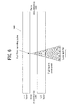
- the optical disc 100 in the example includes the L0 layer as the first recording layer, and the L1 layer as the second recording layer shown in FIG. 2. Then, the laser light for recording is irradiated from the side of a not-illustrated substrate, i.e., from the lower to the upper side in FIG. 6 and FIG. 7, by a not-illustrated optical pickup of the information recording apparatus, and the focal distance thereof or the like is controlled. At the same time, the travel distance and direction in the radial direction of the optical disc are controlled. By this, the data is recorded into each recording layer. Moreover, if the information recording apparatus functions as an information reproducing apparatus, the recorded data is reproduced.
- the unrecorded state of the L0 layer is detected by scanning performed by a CPU, an LD driver, and an optical pickup or the like, which constitute one example of the "setting device" of the present invention.
- a first recording pulse which defines one example of the "preferable irradiation condition" of the present invention is set in the data recording. The details of the first recording pulse will be discussed later.
- the recorded state of the L0 layer is detected by scanning performed by the CPU, the LD driver, and the optical pickup or the like.
- a second recording pulse which defines another example of the "preferable irradiation condition" of the present invention is set in the data recording. The details of the second recording pulse will be discussed later.
- the example is to compensate the increase /decrease in the amount of the light reaching the L1 layer according to the recording or unrecording in the L0 layer, basically on the light source side of the laser light.
- the preferable irradiation condition information as illustrated in FIG. 3 to FIG. 5 is not necessarily recorded on the optical disc 100 side, and is stored in a memory disposed on the information recording apparatus side in the example.
- the preferable irradiation condition information is read if necessary, and used for the setting of the preferable information condition.
- the preferable irradiation condition information what is obtained by performing the OPC process for the optical disc 100 by the information recording apparatus may be stored in the memory disposed on the information recording apparatus side, in a form that the preferable irradiation condition information corresponds to the disc identification number of the optical disc 100, for example.
- the preferable irradiation condition information recorded on the optical disc 100 side, as illustrated in FIG. 3 to FIG. 5, may be read and stored in the memory disposed on the information recording apparatus side.
- FIG. 8 is a graph showing the recording pulse characterized by the pulse intensity which is one specific example of the preferable irradiation condition according to the first example of the information recording apparatus of the present invention, wherein the vertical axis shows the intensity (power) of the recording pulse and the horizontal axis shows time.
- the recording pulse is provided with: a first top pulse top; a plurality of multi pulses mp in which the irradiation time is divided into shorter times; and a cooling pulse cl.
- a time interval in which the top pulse top is irradiated is Ttop
- a time interval in which the multi pulse mp is irradiated is Tmp
- a time interval in which the cooling pulse c1 is irradiated is Tcl.
- a change in the L0 layer from the unrecorded state to the recorded state is detected, under the control of a CPU or the like, in the recording in the L1 layer.
- the setting is changed from a first recording pulse Lw1 to a second recording pulse Lw2.
- the setting of the multi pulse mp is changed to a recording laser power of 12.0 (mW), for example.
- the power is set to a bias laser power, which is weaker than an erasing laser power of 0.6 (mW), for example.
- the cooling pulse cl is provided in the end of the recording pulse, and set to the bias laser power, as with the down time.
- the time interval Tmp in which the multi pulse mp is irradiated is equally set.
- FIG. 9 is a graph showing the recording pulse characterized by the pulse width which is another specific example of the preferable irradiation condition according to the first example of the information recording apparatus of the present invention, wherein the vertical axis and the horizontal axis are the same as those of the above-mentioned explanation in FIG. 8. Moreover, the definition of the top pulse top, the multi pulse mp, and the cooling pulse or the like is also the same as that of the explanation in FIG. 8.
- the setting is changed to increase the time interval Tmp in which the multi pulse mp is irradiated, i.e. to increase the pulse width.
- the intensity of the multi pulse mp may be 8.0 (mW), for example, as in the first recording pulse Lw1.
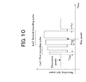
- FIG. 10 is a graph showing a recording pulse characterized by the pulse intensity and the pulse width which are another specific example of the preferable irradiation condition according to the first example of the information recording apparatus of the present invention.
- FIG. 10 is a graph showing a recording pulse characterized by the pulse intensity and the pulse width which are another specific example of the preferable irradiation condition according to the first example of the information recording apparatus of the present invention, wherein the vertical axis and the horizontal axis are the same as those of the above-mentioned explanation in FIG. 8.
- the definition of the top pulse top, the multi pulse mp, and the cooling pulse or the like is also the same as that of the explanation in FIG. 8.
- a gradual change in the L0 layer from the unrecorded state to the recorded state is detected, under the control of the CPU or the like, in the recording in the L1 layer.
- the setting is changed in stages from the first recording pulse Lw1 to the second recording pulse Lw2.
- the top pulse top and the multi pulse mp are set to a recording power of 8.0 (mW), for example, and set to reduce the pulse width.
- the preferable irradiation condition such as the pulse intensity, the pulse width, the pulse shape and the recording strategy, in accordance with the recording state of the L0 layer, in the recording in the L1 layer, under the control of the CPU or the like.
- the optical disc 100 if the optical disc 100 is loaded or mounted, a seek operation is performed by the optical pickup or the like, under the control of the CPU or the like, to thereby obtain various management information required for the recording operation with respect to the optical disc 100.
- the preferable information 101C-0 upon not-recording in the L1 layer if the L0 layer is unrecorded which constitutes one example of the "preferable irradiation condition information" of the present invention recorded in the management information recording area 101B-0, is obtained.
- the ratio or difference information 101D-0 which constitutes one example of the "relationship information" of the present invention, is also obtained.
- the preferable irradiation condition is set on the basis of the preferable information 101C-0 upon not-recording and the ratio or difference information 101D-0.
- the second recording pulse Lw2 with pulse intensity of 12.0 (mW) is irradiated to the L1 layer.
- FIG. 13 is a block diagram showing the information recording / reproducing apparatus 300 according to the example of the present invention.
- the information recording / reproducing apparatus 300 has a function of recording the record data onto the optical disc 100 and a function of reproducing the record data recorded on the optical disc 100.
- the operation control device 307 receives an operation instruction and performs display with respect to the information recording / reproducing apparatus 300, and transmits an instruction by the operation button 310, such as an instruction to record or reproduce, to the CPU 354. Moreover, the operation control device 307 outputs the operational state of the information recording / reproducing apparatus 300, such as during recording and during reproduction, to the display panel 310, such as a fluorescent tube.
- the second recording pulse is set as the preferable irradiation condition (step S108).
- the second recording pulse in the preferable irradiation condition is set.
- the second recording pulse in the preferable irradiation condition is set.
Landscapes
- Physics & Mathematics (AREA)
- Optics & Photonics (AREA)
- Optical Recording Or Reproduction (AREA)
- Debugging And Monitoring (AREA)
- Optical Head (AREA)
Applications Claiming Priority (2)
| Application Number | Priority Date | Filing Date | Title |
|---|---|---|---|
| JP2003340556 | 2003-09-30 | ||
| PCT/JP2004/014229 WO2005031718A1 (fr) | 2003-09-30 | 2004-09-29 | Appareil, procédé et support d'enregistrement d'informations |
Publications (3)
| Publication Number | Publication Date |
|---|---|
| EP1679698A1 true EP1679698A1 (fr) | 2006-07-12 |
| EP1679698A4 EP1679698A4 (fr) | 2009-03-04 |
| EP1679698B1 EP1679698B1 (fr) | 2010-11-03 |
Family
ID=34386208
Family Applications (1)
| Application Number | Title | Priority Date | Filing Date |
|---|---|---|---|
| EP04788295A Expired - Lifetime EP1679698B1 (fr) | 2003-09-30 | 2004-09-29 | Appareil et procede d'enregistrement d'informations |
Country Status (8)
| Country | Link |
|---|---|
| US (1) | US7636282B2 (fr) |
| EP (1) | EP1679698B1 (fr) |
| JP (1) | JPWO2005031718A1 (fr) |
| KR (1) | KR100703148B1 (fr) |
| CN (1) | CN100452182C (fr) |
| AT (1) | ATE487216T1 (fr) |
| DE (1) | DE602004029919D1 (fr) |
| WO (1) | WO2005031718A1 (fr) |
Families Citing this family (9)
| Publication number | Priority date | Publication date | Assignee | Title |
|---|---|---|---|---|
| EP1924990A4 (fr) * | 2005-09-15 | 2008-09-03 | Ricoh Kk | Support d enregistrement optique et dispositif d enregistrement optique |
| JPWO2007046478A1 (ja) * | 2005-10-20 | 2009-04-23 | パナソニック株式会社 | 光制御装置、光情報記録再生装置、光情報記録媒体、光ヘッドの制御方法 |
| JP5028099B2 (ja) * | 2007-02-07 | 2012-09-19 | 株式会社日立製作所 | 多層記録型光ディスク、多層記録型光ディスクの記録方法、および、多層記録型光ディスクの記録装置 |
| JP4810519B2 (ja) * | 2007-09-14 | 2011-11-09 | 株式会社リコー | 多層式追記型光記録媒体及びその記録方法、記録装置 |
| JP2009134785A (ja) | 2007-11-29 | 2009-06-18 | Hitachi-Lg Data Storage Inc | 記録方法及び光ディスク装置 |
| US20100103793A1 (en) * | 2008-10-27 | 2010-04-29 | Panasonic Corporation | Multilayer optical information recording medium, method for recording information in the multilayer optical information recording medium, recording/reproducing apparatus |
| CN102077281A (zh) * | 2008-10-27 | 2011-05-25 | 松下电器产业株式会社 | 信息记录介质、记录装置和再现装置 |
| US20100172226A1 (en) * | 2008-10-27 | 2010-07-08 | Panasonic Corporation | Information recording medium, reproduction apparatus and recording apparatus |
| JP2011175734A (ja) * | 2011-05-12 | 2011-09-08 | Hitachi Ltd | 多層記録型光ディスク、多層記録型光ディスクの記録方法、および、多層記録型光ディスクの記録装置 |
Family Cites Families (9)
| Publication number | Priority date | Publication date | Assignee | Title |
|---|---|---|---|---|
| JP2000293947A (ja) | 1999-04-08 | 2000-10-20 | Matsushita Electric Ind Co Ltd | 光ディスク及び光ディスク記録再生装置、方法 |
| AU8620901A (en) | 2000-09-13 | 2002-03-26 | Matsushita Electric Industrial Co Ltd | Optical information recording medium and optical information recording method, optical information recording device |
| JP4185774B2 (ja) | 2000-10-05 | 2008-11-26 | 松下電器産業株式会社 | 光記録媒体、光記録媒体の記録方法及び光記録媒体の記録装置 |
| US20020126602A1 (en) | 2001-01-11 | 2002-09-12 | Koninklijke Philips Electronics N.V. | Recording on a multilayer record carrier using feed forward power control |
| JP2003022532A (ja) * | 2001-07-06 | 2003-01-24 | Columbia Music Entertainment Inc | 光情報記録媒体ならびにその記録方法および情報記録装置 |
| US20020136122A1 (en) | 2001-03-21 | 2002-09-26 | Kazuhiko Nakano | Optical information record medium, method of recording information on optical information record medium, and information recording apparatus |
| JP4101666B2 (ja) * | 2002-01-22 | 2008-06-18 | 松下電器産業株式会社 | 情報記録媒体、記録装置、再生装置、記録方法、再生方法 |
| US7231649B2 (en) * | 2002-05-31 | 2007-06-12 | Tdk Corporation | Optical recording medium and method for optically recording data in the same |
| JP2004171740A (ja) | 2002-10-28 | 2004-06-17 | Matsushita Electric Ind Co Ltd | 光学式情報記録媒体、光学式記録再生方法及び光学式記録再生装置 |
-
2004
- 2004-09-29 CN CNB2004800325864A patent/CN100452182C/zh not_active Expired - Lifetime
- 2004-09-29 WO PCT/JP2004/014229 patent/WO2005031718A1/fr not_active Ceased
- 2004-09-29 JP JP2005514246A patent/JPWO2005031718A1/ja active Pending
- 2004-09-29 DE DE602004029919T patent/DE602004029919D1/de not_active Expired - Lifetime
- 2004-09-29 US US10/573,762 patent/US7636282B2/en active Active
- 2004-09-29 KR KR1020067008524A patent/KR100703148B1/ko not_active Expired - Lifetime
- 2004-09-29 AT AT04788295T patent/ATE487216T1/de not_active IP Right Cessation
- 2004-09-29 EP EP04788295A patent/EP1679698B1/fr not_active Expired - Lifetime
Also Published As
| Publication number | Publication date |
|---|---|
| HK1090740A1 (en) | 2006-12-29 |
| KR20060081719A (ko) | 2006-07-13 |
| US20060285457A1 (en) | 2006-12-21 |
| JPWO2005031718A1 (ja) | 2006-12-07 |
| EP1679698B1 (fr) | 2010-11-03 |
| KR100703148B1 (ko) | 2007-04-09 |
| EP1679698A4 (fr) | 2009-03-04 |
| WO2005031718A1 (fr) | 2005-04-07 |
| US7636282B2 (en) | 2009-12-22 |
| DE602004029919D1 (de) | 2010-12-16 |
| ATE487216T1 (de) | 2010-11-15 |
| CN100452182C (zh) | 2009-01-14 |
| CN1875405A (zh) | 2006-12-06 |
Similar Documents
| Publication | Publication Date | Title |
|---|---|---|
| US8194516B2 (en) | Information recording apparatus and method | |
| CN100428337C (zh) | 对光记录介质的试写处理控制方法 | |
| EP1679698B1 (fr) | Appareil et procede d'enregistrement d'informations | |
| US8218416B2 (en) | Multi-layer optical disc, information recording method and information reproducing method | |
| US20050030853A1 (en) | Information storage medium and method and apparatus for recording and/or reproducing data | |
| JP2004327038A (ja) | 光記録媒体 | |
| US20050276212A1 (en) | Information record medium, and information record apparatus and method | |
| HK1090740B (en) | Information recording apparatus and method | |
| US7889604B2 (en) | Information recording medium, apparatus, and method, using dummy data in dummy data recording area | |
| CN1981328B (zh) | 信息记录装置 | |
| KR100769625B1 (ko) | 정보 기록 매체, 정보 기록 장치 및 방법 | |
| US20080137509A1 (en) | Recording Medium, Recording Method, and Computer Program | |
| US7885157B2 (en) | Information recording medium, apparatus, and method using management information identifying whether or not embossed pits are formed in a predetermined recording area | |
| EP1873774A1 (fr) | Dispositif et procede d'enregistrement d'informations, programme informatique pour commande d'enregistrement et support d'enregistrement d'informations | |
| US20090268593A1 (en) | Information recording medium, information recording apparatus and method, information reproducing apparatus and method, and computer program | |
| US20090135707A1 (en) | Information recording device and method, computer program and information recording medium | |
| HK1090742A (en) | Information recording medium, and information recording apparatus and method | |
| HK1090741B (en) | Information recording medium, information recording device and method |
Legal Events
| Date | Code | Title | Description |
|---|---|---|---|
| PUAI | Public reference made under article 153(3) epc to a published international application that has entered the european phase |
Free format text: ORIGINAL CODE: 0009012 |
|
| 17P | Request for examination filed |
Effective date: 20060420 |
|
| AK | Designated contracting states |
Kind code of ref document: A1 Designated state(s): AT BE BG CH CY CZ DE DK EE ES FI FR GB GR HU IE IT LI LU MC NL PL PT RO SE SI SK TR |
|
| REG | Reference to a national code |
Ref country code: HK Ref legal event code: DE Ref document number: 1090740 Country of ref document: HK |
|
| DAX | Request for extension of the european patent (deleted) | ||
| A4 | Supplementary search report drawn up and despatched |
Effective date: 20090130 |
|
| 17Q | First examination report despatched |
Effective date: 20090513 |
|
| GRAP | Despatch of communication of intention to grant a patent |
Free format text: ORIGINAL CODE: EPIDOSNIGR1 |
|
| RTI1 | Title (correction) |
Free format text: INFORMATION RECORDING APPARATUS AND METHOD |
|
| GRAS | Grant fee paid |
Free format text: ORIGINAL CODE: EPIDOSNIGR3 |
|
| GRAA | (expected) grant |
Free format text: ORIGINAL CODE: 0009210 |
|
| AK | Designated contracting states |
Kind code of ref document: B1 Designated state(s): AT BE BG CH CY CZ DE DK EE ES FI FR GB GR HU IE IT LI LU MC NL PL PT RO SE SI SK TR |
|
| REG | Reference to a national code |
Ref country code: GB Ref legal event code: FG4D |
|
| REG | Reference to a national code |
Ref country code: CH Ref legal event code: EP |
|
| REG | Reference to a national code |
Ref country code: IE Ref legal event code: FG4D |
|
| REF | Corresponds to: |
Ref document number: 602004029919 Country of ref document: DE Date of ref document: 20101216 Kind code of ref document: P |
|
| RAP2 | Party data changed (patent owner data changed or rights of a patent transferred) |
Owner name: PIONEER CORPORATION |
|
| REG | Reference to a national code |
Ref country code: NL Ref legal event code: VDEP Effective date: 20101103 |
|
| REG | Reference to a national code |
Ref country code: HK Ref legal event code: GR Ref document number: 1090740 Country of ref document: HK |
|
| PG25 | Lapsed in a contracting state [announced via postgrant information from national office to epo] |
Ref country code: FI Free format text: LAPSE BECAUSE OF FAILURE TO SUBMIT A TRANSLATION OF THE DESCRIPTION OR TO PAY THE FEE WITHIN THE PRESCRIBED TIME-LIMIT Effective date: 20101103 Ref country code: BG Free format text: LAPSE BECAUSE OF FAILURE TO SUBMIT A TRANSLATION OF THE DESCRIPTION OR TO PAY THE FEE WITHIN THE PRESCRIBED TIME-LIMIT Effective date: 20110203 Ref country code: NL Free format text: LAPSE BECAUSE OF FAILURE TO SUBMIT A TRANSLATION OF THE DESCRIPTION OR TO PAY THE FEE WITHIN THE PRESCRIBED TIME-LIMIT Effective date: 20101103 Ref country code: PT Free format text: LAPSE BECAUSE OF FAILURE TO SUBMIT A TRANSLATION OF THE DESCRIPTION OR TO PAY THE FEE WITHIN THE PRESCRIBED TIME-LIMIT Effective date: 20110303 Ref country code: SE Free format text: LAPSE BECAUSE OF FAILURE TO SUBMIT A TRANSLATION OF THE DESCRIPTION OR TO PAY THE FEE WITHIN THE PRESCRIBED TIME-LIMIT Effective date: 20101103 Ref country code: SI Free format text: LAPSE BECAUSE OF FAILURE TO SUBMIT A TRANSLATION OF THE DESCRIPTION OR TO PAY THE FEE WITHIN THE PRESCRIBED TIME-LIMIT Effective date: 20101103 Ref country code: AT Free format text: LAPSE BECAUSE OF FAILURE TO SUBMIT A TRANSLATION OF THE DESCRIPTION OR TO PAY THE FEE WITHIN THE PRESCRIBED TIME-LIMIT Effective date: 20101103 |
|
| PG25 | Lapsed in a contracting state [announced via postgrant information from national office to epo] |
Ref country code: GR Free format text: LAPSE BECAUSE OF FAILURE TO SUBMIT A TRANSLATION OF THE DESCRIPTION OR TO PAY THE FEE WITHIN THE PRESCRIBED TIME-LIMIT Effective date: 20110204 |
|
| PG25 | Lapsed in a contracting state [announced via postgrant information from national office to epo] |
Ref country code: BE Free format text: LAPSE BECAUSE OF FAILURE TO SUBMIT A TRANSLATION OF THE DESCRIPTION OR TO PAY THE FEE WITHIN THE PRESCRIBED TIME-LIMIT Effective date: 20101103 Ref country code: EE Free format text: LAPSE BECAUSE OF FAILURE TO SUBMIT A TRANSLATION OF THE DESCRIPTION OR TO PAY THE FEE WITHIN THE PRESCRIBED TIME-LIMIT Effective date: 20101103 Ref country code: ES Free format text: LAPSE BECAUSE OF FAILURE TO SUBMIT A TRANSLATION OF THE DESCRIPTION OR TO PAY THE FEE WITHIN THE PRESCRIBED TIME-LIMIT Effective date: 20110214 Ref country code: CZ Free format text: LAPSE BECAUSE OF FAILURE TO SUBMIT A TRANSLATION OF THE DESCRIPTION OR TO PAY THE FEE WITHIN THE PRESCRIBED TIME-LIMIT Effective date: 20101103 |
|
| PG25 | Lapsed in a contracting state [announced via postgrant information from national office to epo] |
Ref country code: PL Free format text: LAPSE BECAUSE OF FAILURE TO SUBMIT A TRANSLATION OF THE DESCRIPTION OR TO PAY THE FEE WITHIN THE PRESCRIBED TIME-LIMIT Effective date: 20101103 Ref country code: SK Free format text: LAPSE BECAUSE OF FAILURE TO SUBMIT A TRANSLATION OF THE DESCRIPTION OR TO PAY THE FEE WITHIN THE PRESCRIBED TIME-LIMIT Effective date: 20101103 Ref country code: DK Free format text: LAPSE BECAUSE OF FAILURE TO SUBMIT A TRANSLATION OF THE DESCRIPTION OR TO PAY THE FEE WITHIN THE PRESCRIBED TIME-LIMIT Effective date: 20101103 Ref country code: RO Free format text: LAPSE BECAUSE OF FAILURE TO SUBMIT A TRANSLATION OF THE DESCRIPTION OR TO PAY THE FEE WITHIN THE PRESCRIBED TIME-LIMIT Effective date: 20101103 |
|
| PLBE | No opposition filed within time limit |
Free format text: ORIGINAL CODE: 0009261 |
|
| STAA | Information on the status of an ep patent application or granted ep patent |
Free format text: STATUS: NO OPPOSITION FILED WITHIN TIME LIMIT |
|
| 26N | No opposition filed |
Effective date: 20110804 |
|
| REG | Reference to a national code |
Ref country code: DE Ref legal event code: R097 Ref document number: 602004029919 Country of ref document: DE Effective date: 20110804 |
|
| PG25 | Lapsed in a contracting state [announced via postgrant information from national office to epo] |
Ref country code: IT Free format text: LAPSE BECAUSE OF FAILURE TO SUBMIT A TRANSLATION OF THE DESCRIPTION OR TO PAY THE FEE WITHIN THE PRESCRIBED TIME-LIMIT Effective date: 20101103 |
|
| PG25 | Lapsed in a contracting state [announced via postgrant information from national office to epo] |
Ref country code: MC Free format text: LAPSE BECAUSE OF NON-PAYMENT OF DUE FEES Effective date: 20110930 |
|
| REG | Reference to a national code |
Ref country code: CH Ref legal event code: PL |
|
| REG | Reference to a national code |
Ref country code: IE Ref legal event code: MM4A |
|
| PG25 | Lapsed in a contracting state [announced via postgrant information from national office to epo] |
Ref country code: IE Free format text: LAPSE BECAUSE OF NON-PAYMENT OF DUE FEES Effective date: 20110929 Ref country code: CH Free format text: LAPSE BECAUSE OF NON-PAYMENT OF DUE FEES Effective date: 20110930 Ref country code: LI Free format text: LAPSE BECAUSE OF NON-PAYMENT OF DUE FEES Effective date: 20110930 |
|
| REG | Reference to a national code |
Ref country code: GB Ref legal event code: 746 Effective date: 20121119 |
|
| PG25 | Lapsed in a contracting state [announced via postgrant information from national office to epo] |
Ref country code: CY Free format text: LAPSE BECAUSE OF EXPIRATION OF PROTECTION Effective date: 20101103 Ref country code: LU Free format text: LAPSE BECAUSE OF NON-PAYMENT OF DUE FEES Effective date: 20110929 |
|
| PG25 | Lapsed in a contracting state [announced via postgrant information from national office to epo] |
Ref country code: TR Free format text: LAPSE BECAUSE OF FAILURE TO SUBMIT A TRANSLATION OF THE DESCRIPTION OR TO PAY THE FEE WITHIN THE PRESCRIBED TIME-LIMIT Effective date: 20101103 |
|
| PG25 | Lapsed in a contracting state [announced via postgrant information from national office to epo] |
Ref country code: HU Free format text: LAPSE BECAUSE OF FAILURE TO SUBMIT A TRANSLATION OF THE DESCRIPTION OR TO PAY THE FEE WITHIN THE PRESCRIBED TIME-LIMIT Effective date: 20101103 |
|
| REG | Reference to a national code |
Ref country code: FR Ref legal event code: PLFP Year of fee payment: 13 |
|
| REG | Reference to a national code |
Ref country code: FR Ref legal event code: PLFP Year of fee payment: 14 |
|
| REG | Reference to a national code |
Ref country code: FR Ref legal event code: PLFP Year of fee payment: 15 |
|
| PGFP | Annual fee paid to national office [announced via postgrant information from national office to epo] |
Ref country code: GB Payment date: 20230810 Year of fee payment: 20 |
|
| PGFP | Annual fee paid to national office [announced via postgrant information from national office to epo] |
Ref country code: FR Payment date: 20230808 Year of fee payment: 20 Ref country code: DE Payment date: 20230802 Year of fee payment: 20 |
|
| REG | Reference to a national code |
Ref country code: DE Ref legal event code: R071 Ref document number: 602004029919 Country of ref document: DE |
|
| PG25 | Lapsed in a contracting state [announced via postgrant information from national office to epo] |
Ref country code: GB Free format text: LAPSE BECAUSE OF EXPIRATION OF PROTECTION Effective date: 20240928 |
|
| REG | Reference to a national code |
Ref country code: GB Ref legal event code: PE20 Expiry date: 20240928 |
|
| PG25 | Lapsed in a contracting state [announced via postgrant information from national office to epo] |
Ref country code: GB Free format text: LAPSE BECAUSE OF EXPIRATION OF PROTECTION Effective date: 20240928 |