EP1680362B1 - Flüssigkeitsfiltrationsapparatur und -verfahren mit superschwimmfähigen filtrationsteilchen - Google Patents
Flüssigkeitsfiltrationsapparatur und -verfahren mit superschwimmfähigen filtrationsteilchen Download PDFInfo
- Publication number
- EP1680362B1 EP1680362B1 EP04778021A EP04778021A EP1680362B1 EP 1680362 B1 EP1680362 B1 EP 1680362B1 EP 04778021 A EP04778021 A EP 04778021A EP 04778021 A EP04778021 A EP 04778021A EP 1680362 B1 EP1680362 B1 EP 1680362B1
- Authority
- EP
- European Patent Office
- Prior art keywords
- filter
- liquid
- bed
- process liquid
- media
- Prior art date
- Legal status (The legal status is an assumption and is not a legal conclusion. Google has not performed a legal analysis and makes no representation as to the accuracy of the status listed.)
- Expired - Lifetime
Links
- 239000007788 liquid Substances 0.000 title claims abstract description 411
- 238000000034 method Methods 0.000 title claims abstract description 255
- 238000001914 filtration Methods 0.000 title claims abstract description 142
- 239000002245 particle Substances 0.000 title claims description 141
- 230000008569 process Effects 0.000 claims abstract description 230
- 239000007921 spray Substances 0.000 claims abstract description 49
- 230000005484 gravity Effects 0.000 claims abstract description 39
- 239000000356 contaminant Substances 0.000 claims description 72
- 238000011001 backwashing Methods 0.000 claims description 33
- 239000000463 material Substances 0.000 claims description 31
- XLYOFNOQVPJJNP-UHFFFAOYSA-N water Substances O XLYOFNOQVPJJNP-UHFFFAOYSA-N 0.000 claims description 29
- 229910052751 metal Inorganic materials 0.000 claims description 20
- 239000002184 metal Substances 0.000 claims description 20
- 239000004033 plastic Substances 0.000 claims description 13
- 229920003023 plastic Polymers 0.000 claims description 13
- 239000012530 fluid Substances 0.000 claims description 12
- 230000000694 effects Effects 0.000 claims description 9
- 238000003860 storage Methods 0.000 claims description 9
- 230000009977 dual effect Effects 0.000 claims description 8
- 239000011521 glass Substances 0.000 claims description 7
- 238000005406 washing Methods 0.000 claims description 7
- 239000000919 ceramic Substances 0.000 claims description 6
- 230000002209 hydrophobic effect Effects 0.000 claims description 5
- 230000002829 reductive effect Effects 0.000 claims description 3
- 239000002131 composite material Substances 0.000 claims 4
- 238000007599 discharging Methods 0.000 claims 1
- 239000011236 particulate material Substances 0.000 abstract description 3
- 239000010410 layer Substances 0.000 description 34
- 230000007246 mechanism Effects 0.000 description 24
- VYPSYNLAJGMNEJ-UHFFFAOYSA-N Silicium dioxide Chemical compound O=[Si]=O VYPSYNLAJGMNEJ-UHFFFAOYSA-N 0.000 description 19
- 230000000630 rising effect Effects 0.000 description 16
- 238000004140 cleaning Methods 0.000 description 14
- 238000007667 floating Methods 0.000 description 13
- 230000000717 retained effect Effects 0.000 description 10
- 239000004576 sand Substances 0.000 description 10
- 239000005909 Kieselgur Substances 0.000 description 9
- 230000003749 cleanliness Effects 0.000 description 9
- 238000013461 design Methods 0.000 description 9
- 230000037452 priming Effects 0.000 description 8
- 238000011118 depth filtration Methods 0.000 description 7
- 150000002739 metals Chemical class 0.000 description 7
- 239000012528 membrane Substances 0.000 description 6
- 239000000203 mixture Substances 0.000 description 6
- 238000005086 pumping Methods 0.000 description 6
- 238000007792 addition Methods 0.000 description 5
- 239000007864 aqueous solution Substances 0.000 description 5
- -1 hydroxyl ions Chemical class 0.000 description 5
- 239000011148 porous material Substances 0.000 description 5
- 239000007787 solid Substances 0.000 description 5
- 230000004888 barrier function Effects 0.000 description 4
- 239000003637 basic solution Substances 0.000 description 4
- 230000015572 biosynthetic process Effects 0.000 description 4
- 239000004005 microsphere Substances 0.000 description 4
- 239000002244 precipitate Substances 0.000 description 4
- 230000005855 radiation Effects 0.000 description 4
- 230000005070 ripening Effects 0.000 description 4
- KWYUFKZDYYNOTN-UHFFFAOYSA-M Potassium hydroxide Chemical compound [OH-].[K+] KWYUFKZDYYNOTN-UHFFFAOYSA-M 0.000 description 3
- HEMHJVSKTPXQMS-UHFFFAOYSA-M Sodium hydroxide Chemical compound [OH-].[Na+] HEMHJVSKTPXQMS-UHFFFAOYSA-M 0.000 description 3
- 238000009825 accumulation Methods 0.000 description 3
- 230000008901 benefit Effects 0.000 description 3
- 238000000576 coating method Methods 0.000 description 3
- 238000013327 media filtration Methods 0.000 description 3
- 230000007935 neutral effect Effects 0.000 description 3
- 238000001556 precipitation Methods 0.000 description 3
- 239000000047 product Substances 0.000 description 3
- 239000000126 substance Substances 0.000 description 3
- 238000011282 treatment Methods 0.000 description 3
- 239000002699 waste material Substances 0.000 description 3
- 239000002253 acid Substances 0.000 description 2
- 239000002585 base Substances 0.000 description 2
- 229910010293 ceramic material Inorganic materials 0.000 description 2
- 239000000470 constituent Substances 0.000 description 2
- 238000007796 conventional method Methods 0.000 description 2
- 239000008367 deionised water Substances 0.000 description 2
- 229910021641 deionized water Inorganic materials 0.000 description 2
- 238000010586 diagram Methods 0.000 description 2
- 239000006185 dispersion Substances 0.000 description 2
- 238000009826 distribution Methods 0.000 description 2
- 238000009760 electrical discharge machining Methods 0.000 description 2
- 238000002347 injection Methods 0.000 description 2
- 239000007924 injection Substances 0.000 description 2
- 239000007769 metal material Substances 0.000 description 2
- 238000002156 mixing Methods 0.000 description 2
- 238000012986 modification Methods 0.000 description 2
- 230000004048 modification Effects 0.000 description 2
- 239000003921 oil Substances 0.000 description 2
- 150000002894 organic compounds Chemical class 0.000 description 2
- 229920000642 polymer Polymers 0.000 description 2
- 238000000926 separation method Methods 0.000 description 2
- 239000000243 solution Substances 0.000 description 2
- 230000002269 spontaneous effect Effects 0.000 description 2
- 241000206761 Bacillariophyta Species 0.000 description 1
- 235000008733 Citrus aurantifolia Nutrition 0.000 description 1
- 235000011941 Tilia x europaea Nutrition 0.000 description 1
- 150000007513 acids Chemical class 0.000 description 1
- 230000009471 action Effects 0.000 description 1
- 230000006978 adaptation Effects 0.000 description 1
- 238000013459 approach Methods 0.000 description 1
- 230000001580 bacterial effect Effects 0.000 description 1
- 238000003486 chemical etching Methods 0.000 description 1
- 238000009388 chemical precipitation Methods 0.000 description 1
- 238000006243 chemical reaction Methods 0.000 description 1
- 239000011248 coating agent Substances 0.000 description 1
- 230000001427 coherent effect Effects 0.000 description 1
- 239000012141 concentrate Substances 0.000 description 1
- 238000011109 contamination Methods 0.000 description 1
- 239000002826 coolant Substances 0.000 description 1
- 239000007799 cork Substances 0.000 description 1
- 238000005260 corrosion Methods 0.000 description 1
- 230000007797 corrosion Effects 0.000 description 1
- 230000003247 decreasing effect Effects 0.000 description 1
- 238000006073 displacement reaction Methods 0.000 description 1
- 238000005516 engineering process Methods 0.000 description 1
- 239000004794 expanded polystyrene Substances 0.000 description 1
- 239000004744 fabric Substances 0.000 description 1
- 238000011049 filling Methods 0.000 description 1
- 239000010419 fine particle Substances 0.000 description 1
- 238000011010 flushing procedure Methods 0.000 description 1
- 230000004907 flux Effects 0.000 description 1
- 239000003292 glue Substances 0.000 description 1
- 238000003306 harvesting Methods 0.000 description 1
- 125000002887 hydroxy group Chemical group [H]O* 0.000 description 1
- 238000007654 immersion Methods 0.000 description 1
- 230000000977 initiatory effect Effects 0.000 description 1
- 239000004571 lime Substances 0.000 description 1
- 230000000670 limiting effect Effects 0.000 description 1
- 238000003754 machining Methods 0.000 description 1
- 238000011093 media selection Methods 0.000 description 1
- 229910000000 metal hydroxide Inorganic materials 0.000 description 1
- 150000004692 metal hydroxides Chemical class 0.000 description 1
- 229910021645 metal ion Inorganic materials 0.000 description 1
- 230000000813 microbial effect Effects 0.000 description 1
- 244000005700 microbiome Species 0.000 description 1
- 239000003960 organic solvent Substances 0.000 description 1
- 230000001151 other effect Effects 0.000 description 1
- 238000012856 packing Methods 0.000 description 1
- 239000003973 paint Substances 0.000 description 1
- 239000000123 paper Substances 0.000 description 1
- 230000036961 partial effect Effects 0.000 description 1
- 239000013618 particulate matter Substances 0.000 description 1
- 230000037361 pathway Effects 0.000 description 1
- 238000009877 rendering Methods 0.000 description 1
- 238000012552 review Methods 0.000 description 1
- 239000010865 sewage Substances 0.000 description 1
- 238000004904 shortening Methods 0.000 description 1
- 239000002356 single layer Substances 0.000 description 1
- 230000003068 static effect Effects 0.000 description 1
- 230000009182 swimming Effects 0.000 description 1
- 230000003442 weekly effect Effects 0.000 description 1
Images



Classifications
-
- C—CHEMISTRY; METALLURGY
- C02—TREATMENT OF WATER, WASTE WATER, SEWAGE, OR SLUDGE
- C02F—TREATMENT OF WATER, WASTE WATER, SEWAGE, OR SLUDGE
- C02F1/00—Treatment of water, waste water, or sewage
- C02F1/001—Processes for the treatment of water whereby the filtration technique is of importance
- C02F1/004—Processes for the treatment of water whereby the filtration technique is of importance using large scale industrial sized filters
-
- B—PERFORMING OPERATIONS; TRANSPORTING
- B01—PHYSICAL OR CHEMICAL PROCESSES OR APPARATUS IN GENERAL
- B01D—SEPARATION
- B01D21/00—Separation of suspended solid particles from liquids by sedimentation
- B01D21/0012—Settling tanks making use of filters, e.g. by floating layers of particulate material
-
- B—PERFORMING OPERATIONS; TRANSPORTING
- B01—PHYSICAL OR CHEMICAL PROCESSES OR APPARATUS IN GENERAL
- B01D—SEPARATION
- B01D24/00—Filters comprising loose filtering material, i.e. filtering material without any binder between the individual particles or fibres thereof
- B01D24/02—Filters comprising loose filtering material, i.e. filtering material without any binder between the individual particles or fibres thereof with the filter bed stationary during the filtration
- B01D24/10—Filters comprising loose filtering material, i.e. filtering material without any binder between the individual particles or fibres thereof with the filter bed stationary during the filtration the filtering material being held in a closed container
- B01D24/16—Upward filtration
- B01D24/165—Upward filtration the filtering material being supported by pervious surfaces
-
- B—PERFORMING OPERATIONS; TRANSPORTING
- B01—PHYSICAL OR CHEMICAL PROCESSES OR APPARATUS IN GENERAL
- B01D—SEPARATION
- B01D24/00—Filters comprising loose filtering material, i.e. filtering material without any binder between the individual particles or fibres thereof
- B01D24/36—Filters comprising loose filtering material, i.e. filtering material without any binder between the individual particles or fibres thereof with the filter bed fluidised during the filtration
-
- B—PERFORMING OPERATIONS; TRANSPORTING
- B01—PHYSICAL OR CHEMICAL PROCESSES OR APPARATUS IN GENERAL
- B01D—SEPARATION
- B01D24/00—Filters comprising loose filtering material, i.e. filtering material without any binder between the individual particles or fibres thereof
- B01D24/46—Regenerating the filtering material in the filter
- B01D24/4631—Counter-current flushing, e.g. by air
- B01D24/4636—Counter-current flushing, e.g. by air with backwash shoes; with nozzles
-
- C—CHEMISTRY; METALLURGY
- C02—TREATMENT OF WATER, WASTE WATER, SEWAGE, OR SLUDGE
- C02F—TREATMENT OF WATER, WASTE WATER, SEWAGE, OR SLUDGE
- C02F1/00—Treatment of water, waste water, or sewage
- C02F1/30—Treatment of water, waste water, or sewage by irradiation
- C02F1/32—Treatment of water, waste water, or sewage by irradiation with ultraviolet light
-
- C—CHEMISTRY; METALLURGY
- C02—TREATMENT OF WATER, WASTE WATER, SEWAGE, OR SLUDGE
- C02F—TREATMENT OF WATER, WASTE WATER, SEWAGE, OR SLUDGE
- C02F2101/00—Nature of the contaminant
- C02F2101/10—Inorganic compounds
- C02F2101/20—Heavy metals or heavy metal compounds
-
- C—CHEMISTRY; METALLURGY
- C02—TREATMENT OF WATER, WASTE WATER, SEWAGE, OR SLUDGE
- C02F—TREATMENT OF WATER, WASTE WATER, SEWAGE, OR SLUDGE
- C02F2103/00—Nature of the water, waste water, sewage or sludge to be treated
- C02F2103/16—Nature of the water, waste water, sewage or sludge to be treated from metallurgical processes, i.e. from the production, refining or treatment of metals, e.g. galvanic wastes
-
- C—CHEMISTRY; METALLURGY
- C02—TREATMENT OF WATER, WASTE WATER, SEWAGE, OR SLUDGE
- C02F—TREATMENT OF WATER, WASTE WATER, SEWAGE, OR SLUDGE
- C02F2103/00—Nature of the water, waste water, sewage or sludge to be treated
- C02F2103/42—Nature of the water, waste water, sewage or sludge to be treated from bathing facilities, e.g. swimming pools
-
- Y—GENERAL TAGGING OF NEW TECHNOLOGICAL DEVELOPMENTS; GENERAL TAGGING OF CROSS-SECTIONAL TECHNOLOGIES SPANNING OVER SEVERAL SECTIONS OF THE IPC; TECHNICAL SUBJECTS COVERED BY FORMER USPC CROSS-REFERENCE ART COLLECTIONS [XRACs] AND DIGESTS
- Y02—TECHNOLOGIES OR APPLICATIONS FOR MITIGATION OR ADAPTATION AGAINST CLIMATE CHANGE
- Y02A—TECHNOLOGIES FOR ADAPTATION TO CLIMATE CHANGE
- Y02A20/00—Water conservation; Efficient water supply; Efficient water use
- Y02A20/152—Water filtration
Definitions
- the present invention relates to an apparatus and method for filtering particulates of various sizes from miscellaneous process liquids, and more particularly to an apparatus and method that utilizes a filtration bed formed from super-buoyant media, which has a specific gravity much lower than that of the liquid being filtered.
- media filtration particulate contaminants are strained from the process liquid in one of two ways, either by pumping the contaminated liquid through a unitary permeable element, or by pumping the liquid through a filter bed that is itself composed of small particles.
- Permeable elements comprise a variety of materials, including fabric, paper, ceramic, metal, and plastic. These elements filter the liquid primarily by capturing the contaminant particles on the surface of the element, thus building up a crust or layer of contaminants on the surface. As contaminants accumulate on the surface of the element, liquid flow through the permeable element is reduced because the crust or layer of contaminants acts as an obstruction and because an increasing number of the pores or channels become blocked. As the percentage of blocked pores/channels increases and the crust or layer of contaminants becomes thicker, the pressure required to maintain a specific rate of flow of liquid through the element increases. Eventually, the pressure required exceeds the capability of the pump, or some other system component, and the contaminated element must be replaced with a new element in order to maintain the desired performance of the filtration system.
- an attempt may be made to clean the filter element (e.g., by backwashing it with clean liquid or air) to remove the contaminants accumulated on the surface.
- the filter element e.g., by backwashing it with clean liquid or air
- the element must either be replaced with a new element or cleaned in a more rigorous fashion, i.e. by immersion in an acid or base solution to dissolve the contaminants. The more frequently such element replacement or stringent cleaning must be performed, the more costly this filtration process becomes.
- the second type of media filtration uses a filter bed composed of small particles such as sand or diatomaceous earth, and is one of the most common conventional methods of removing particulate contaminants from liquids.
- the sand filter uses sand particles that are about 0.35 mm in diameter and fairly uniform in size.
- Diatomaceous earth filters use a siliceous material formed from the skeletons of small (about 100 microns [ ⁇ m] in diameter) marine algal cells called diatoms. Both sand and diatomaceous earth filters use media that are substantially heavier than the process liquid being filtered, so that the media sink to the bottom of the filtration vessel forming a bed of filter media. This bed may have different thickness.
- the process liquid is pumped, or allowed to flow (via gravity), downward through this filter bed.
- the particulate-laden liquid passes through the bed, the particulates are strained from the liquid and the cleaned liquid exits at the bottom of the bed.
- the bed removes the particulate contaminants via one of two processes.
- This straining effect produces a layer or crust (also called a cake) of large contaminant particles, which builds up on the surface of the bed, a mechanism called surface filtration.
- This cake can actually enhance the performance of the bed by helping to capture more contaminant particulates, which are retained in the crust itself, because they cannot pass through the spaces between the contaminant particles that form the crust.
- the size and cleanliness of the bed particles are extremely important to the success of the filtration process; a bed composed of large particles allows significant numbers of small particulates to pass through the filter bed along with the process liquid. On the other hand, beds composed of smaller particles can quickly become clogged with small contaminant particles, thus rendering the filter bed ineffective.
- the bed particles can also adsorb organic compounds on which microorganisms feed. Microbes growing on these organic compounds can bind the filter particles together and clog the bed, thus decreasing its effectiveness and shortening the interval until cleaning.
- An alternative method of bed filtration uses a filter bed composed of buoyant filter media particles.
- the media form a bed in which the majority of the media floats just beneath the surface of the process liquid.
- the process liquid is pumped into the bottom of the filter chamber and flows vertically upward through the bed. As the process liquid passes through the bed, contaminants are filtered from the liquid via the surface and depth filtration mechanisms described above.
- the buoyant media particles used in this type of application are also of a larger diameter than the media particles used in either sand or diatomaceous earth filters.
- Hsiung, et al. specify the particle diameter as being preferably in the range of 1.5 to 20 mm, in contrast to the sizes of sand particles (about 0.35 mm in diameter) and diatomaceous earth (about 100 microns ( ⁇ m) in diameter).
- these buoyant media filter beds are not optimized to remove small particulate contaminants. In general, they are designed to perform larger particulate contaminant removal and some degree of biofiltration of the process liquid by the bacterial biofilm adhering to the media particles.
- backwashing must be performed in a gentle fashion to preserve the "ripened" layer on the filter media: If the backwash is especially vigorous, particles that were adhering to the buoyant media will be removed from the media and a portion of the buoyant media's filtration capacity would thus be lost. That capacity cannot be regained until the filter has "ripened” by again filtering a sufficient amount of contaminant particles and retaining them in the filter media in order to replenish the loss.
- backwashing is typically performed by gently agitating the bed with air bubbles introduced beneath the bed and allowed to flow upwards through the bed or by gentle streams of water directed into the bed to agitate and dislodge some of the adhering contaminant particles.
- these backwash methods flush only a portion of the retained contaminants from the filter bed.
- the backwash system described by Hsiung et al. is the type that uses air injection and the normal flow of raw process liquid to wash excess particulates out of the media. Because the buoyant media particles have a specific gravity close to that of water, it is easy for these gentle agitating mechanisms to move the mostly submerged media around in the process liquid, and thus dislodge some of the contaminant particulates adhering to the media. Consequently, these mechanisms provide the required minimal degree of cleaning of the filter media bed. Using this method of backwashing, the amount of solids flushed from the buoyant media depends on total wash volume. However, because the media particles have a specific gravity close to that of water, they are moved easily by the backwash mechanism, and cannot be thoroughly cleaned.
- the document JP10028817 (by Tepitsukusu ) describes another method for washing floating filter material, where a cleaning fluid is supplied from a cleaning nozzle and is injected towards the upper part of the filter main body. The flooting filter medium is moved vertically during the washing process.
- buoyant media filter systems do not employ a separate backwash pump or backwash water storage system.
- raw process liquid is used to backwash the bed media.
- maximum cleanliness of the media particles cannot be achieved because a separate, isolated pump and process liquid storage system are not utilized to provide a source of clean process liquid for backwashing.
- buoyant media filters have desirable characteristics for specific filtration applications, they do not overcome the above-stated disadvantages of conventional media bed filters.
- Another object of the present invention is to provide a liquid filtration apparatus and method that embodies a filtration bed formed from super-buoyant particles having a specific gravity less than one half that of the liquid being filtered.
- a still further object of the invention is to provide a liquid filtration apparatus that embodies a filtration bed that floats on the liquid to be filtered.
- Yet another object of the invention is to provide a new and improved filtering system for the removal of particulate contaminants from process liquids which incorporates a high-efficiency back-washable filter bed.
- a still further object of the invention is the provision of a liquid filtration apparatus and method that in one aspect incorporates a pair of filtration housings connected in parallel.
- Yet another object of the invention is the provision of a liquid filtration apparatus and method that in another aspect incorporates a pair of filtration housings connected in series.
- the invention disclosed herein overcomes the disadvantages encountered with prior bed filtration systems by providing a filtering apparatus which incorporates a super-buoyant filter medium having a specific gravity very substantially lower than that of the process liquid being filtered. This requirement permits a majority of the medium to float on top of the process liquid.
- buoyant media filters use filter media which are at or near neutral buoyancy in the process liquid, and therefore float with the majority of the media just below the surface of the process liquid.
- Hsiung et al. specifically define buoyant filter media as having a specific gravity of no lower than 0.8 and "most preferably” no lower than 0.9. Using a specific gravity value of 0.9, the amount of a buoyant media particle that floats above the surface of the process liquid can be calculated using fundamental physical principles.
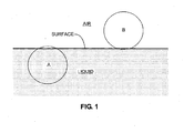
- a sphere 1 cubic centimeter in volume will have a mass of 0.9 grams. If that sphere is placed in water, it will displace 0.9 cubic centimeters of volume. This displacement means that 0.1 cubic centimeter of the sphere, or 10%, will be visible above the surface of the water as shown in Figure 1 , neglecting surface tension and other effects described below. Thus, 90% of the buoyant media sphere will actually be immersed beneath the water's surface. If several spheres are stacked on top of one another to increase the thickness of the media layer, the relationship remains the same, so that 90% of the media thickness will still be immersed in the water and 10% will be exposed above the water.
- super-buoyant media In contrast to buoyant media, super-buoyant media form a mass in which the majority of the media floats on top of the process liquid (i.e., in which the media have a specific gravity less than one-half that of the process liquid). For clarity, this difference is illustrated in FIG. 1 .
- the use of super-buoyant media that float principally on top of the process liquid is a design feature that provides unique capabilities not provided by the buoyant media filter designs described in Hsiung, et al., Banks, Muller et al., or any of the other filtration systems described previously.
- filter media floating submerged beneath the surface of the process liquid is critical in determining the unique operational characteristics of the each kind of filter.
- the filter media behave principally as though they are part of the water mass.
- any horizontal movement of the water containing such media drags the media along with it.
- An injection of air bubbles into such a media bed will also move the media particles because they are very close to neutral buoyancy, and this neutral buoyancy renders them easy to move.
- super-buoyant media filter particles (B in FIG. 1 ) do not behave as though they are part of the process liquid mass. Instead, they form a mass that floats on the surface of the process liquid, largely independent of, and isolated from, the movements of the process liquid beneath. Horizontal movements of the liquid beneath the floating, super-buoyant media have virtually no effect on the media, and thus such movements do not tend to cause significant movement of the super-buoyant media bed. In essence, the super-buoyant media described herein behave much like a cork floating on a water surface.
- the super-buoyant media particles must have a nominal specific gravity less than 50% of the specific gravity of the process liquid to be filtered.
- utilizing a super-buoyant media with the lowest possible specific gravity maximizes the effectiveness of both the filtration and backwashing mechanisms.
- good performance can be achieved when the specific gravity of the super-buoyant filter media is less than or equal to approximately 0.25-0.35, but the best performance is achieved when the specific gravity of the super-buoyant media is in the range of 0.01 to 0.05.
- These super-buoyant media are typically selected from materials such as lightweight plastics (e.g., expanded polystyrene), or hollow microspheres formed from glass or ceramic.
- the uniqueness of the super-buoyant media approach stems from the fact that when such super-buoyant filter media are used, the aggregate forces acting on the media produce a natural, spontaneous, gravimetric separation of the filter media and the process liquid into two different phases. This occurs in the same manner that a well-agitated mixture of oil and water separates naturally into two distinct phases when a mixture of the two is allowed to reach a static equilibrium.
- the super-buoyant media of the filter described here is one of its most novel and unique aspects, as it provides a method for naturally, easily, and efficiently separating the filter media and trapped contaminants from the process liquid.
- implementation of the super-buoyant media method requires that the filter media must float principally on the surface of the process liquid. This requirement is satisfied primarily by selecting media that are much lighter in density than the process liquid. Thus, selection of the appropriate media to implement this filtration method must be initially dictated by the specific gravity of the process liquid. However, selecting media with a low specific gravity is not always sufficient to identify an optimal filter media for filtration of a specific process liquid. Other factors can also influence the effectiveness of the super-buoyant media as a filter for a given process liquid, and therefore must also be considered in selecting the type of filter media.
- the second factor in selecting the type of super-buoyant filter media is the attraction of the filter media particles to one another. If, for instance, there is a weak electrostatic attraction between the filter media particles, the particles tend to adhere to one another. As a consequence, through selection of media material (e.g., plastic, ceramic, or glass), this electrostatic effect can be utilized to assist the filter media in forming a coherent mass that floats better on the surface of the process liquid, as well as assisting in attraction and removal of contaminant particles from the process liquid. If the electrostatic attraction between the media particles is too great, however, the particles will tend to stick to one another too strongly, thus forming clumps that can cause bed inhomogeneities or interfere with the removal of contaminants from the bed during backwashing. In this later case, it may be necessary to include in the filter housing, a means of electrically grounding the media to remove the charge
- the filter bed generally works best when the media particles are uniformly spherical in shape as this shape allows the most efficient packing of the media particles. Deviations from a spherical shape can lead to inhomogeneities in the bed, which in turn can decrease the effectiveness of the filter and significantly complicate cleaning of the media.
- the final factor that must be taken into account in selecting the type of super-buoyant media is the nature of the process liquid and the physical conditions under which the process functions. Practitioners of the art will easily recognize that there are many organic solvents in which plastic filter media would dissolve, and therefore would not be suitable. In such cases, the use of ceramic or glass microspheres is dictated. In other cases, such as strong acids or bases, the process liquid is extremely corrosive, and corrosion-resistant plastics or glass microspheres must be used. In some cases, the process liquid may operate at elevated temperatures or pressures that would rapidly degrade some types of plastic filter media, and ceramic microspheres would be required.
- the surface of the super-buoyant media particles may be altered by subjecting the particles to various physical or chemical treatments, including high temperature, high pressure, chemical etching, etc. These treatments are capable of modifying the surface of the media particles, for example, making it more or less hydrophobic in some cases or more or less hydrophilic in others. It is also possible to apply a polymer coating to these media particles. Such polymer coatings may determine the surface properties of the media directly, or the coatings may contain additional embedded chemicals that produce different surface properties for the media. These embedded chemicals can be selected to optimize specific aspects of the super-buoyant media, thus affecting the manner in which the filter functions.
- the super-buoyant media particles should be as small as possible, and should be chosen based upon the size of the contaminants to be removed.
- Candidate media are currently available in diameters as small as 10 ⁇ m and as large as several cm.
- the performance of the filter is also influenced by the thickness of the media layer.
- the use of thicker beds composed of larger diameter media particles generally offers good depth filtration.
- the use of thinner beds composed of smaller diameter media particles generally offer good surface filtration.
- the efficiency of the filter bed can be tailored to meet a variety of filtration problems.
- Using smaller diameter media or thicker media beds carry a power penalty, however, as a more powerful, high pressure pump is required to force the process liquid through such a super-buoyant media bed.
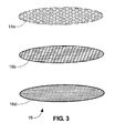
- a strong, multicomponent "sandwich” is used as a bed restraint 16 ( FIGS. 2 , 3 ). In both FIGS.
- a perforated metal plate 16a provides support for the bed restraint 16.
- An intermediate layer of coarse screen 16b provides additional support as well as facilitates passage of the process liquid through the bed restraint 16.
- the final layer of the "sandwich” is either a very fine mesh screen 16c ( FIG. 2 ) for medium or coarse filter media, or a sheet of permeable metal or plastic material 16d ( FIG. 3 ) for fine filter media.
- a thin layer of super-buoyant media is a preferable choice for filtering process liquid.
- it may be necessary to insure a uniformly thin media layer by adding a ring grid 16e ( FIG. 4 ) to the bed restraint 16 described above.
- this bed restraint 16 consists of a perforated metal plate 16a, an intermediate layer of course screen 16b and a final layer of fine screen (not shown) or a sheet of permeable metal or plastic material 16d.
- the ring grid 16e in combination with the directed flow of the process liquid, or, occasionally, in conjunction with other mechanical rotating mechanisms, assists in maintaining a uniform, thin media layer to maximize the surface filtration provided by the media.
- Other grid designs e.g., where the open area is filled with small square, rectangular, or hexagonal cells, rather than a single large central open area, may also be used to assist in maximizing the amount of surface filtration achieved.
- FIGS. 5A-5F The most effective way to clean a super-buoyant media filter bed is to use a rigorous spray of clean process liquid while forcing the entire bed to move through the spray.
- a normally-operating filter FIG. 5A
- FIG. 5B the process liquid is flowing upward through the media bed 14
- FIG. 5C the drain valve (not shown) is closed and the backwash spray 5 of clean process liquid is turned on ( FIG. 5C ).
- this backwash sequence may be repeated as many times as required to provide the desired level of media cleanliness.
- the amount of clean process liquid required for a single backwash is usually no more than 2-3 times the volume of the filter media bed.
- the filter housing is assumed to be cylindrical in shape, other housing shapes may be selected for specific applications to increase either or both the filtration efficiency or the backwashing efficiency.
- Several alternative, non-cylindrical housings 13a-13c are pictured in FIG. 6 . All of these alternatives provide a larger filtration area and a "necked-down" backwashing section 10. These features enhance the total area of the super-buoyant media available for filtration, as well as providing a means of concentrating the backwash spray to increase its cleaning effectiveness.
- the novel backwash mechanism described herein makes it possible to thoroughly scour and clean small diameter filter media, thus providing an unprecedented level of cleanliness in the backwashed media.
- the media does not have to be discarded nearly as frequently as previous filters which used small diameter, non-buoyant media, thus making the super-buoyant media filter design significantly more economical to operate as well as more efficient in removing contaminants.
- the cleaned super-buoyant media bed retains its initial filtration characteristics, and performs in a repeatable fashion after every backwash cycle, all without requiring any sort of "ripening".
- the life of the media is also very significantly extended over that experienced with non-buoyant media.
- because of the high efficiency of the backwash mechanism very little particulate-laden waste process liquid is generated.
- the liquid to be filtered is withdrawn from a process tank or process stream and pumped under pressure through one or more filter housings containing the aforementioned super-buoyant bed medium.
- the liquid being filtered is pumped into the dry housing at the bottom, elevates the filter bed by floatation to a position where further elevation is restrained and then rises through the restrained bed medium, exiting the filter housing at the top.
- a valve in the exit line at the top of the housing directs the filtered liquid either back into the process tank or stream, or into a clean liquid storage tank.
- a small storage tank in the filtration system provides a volume of filtered liquid for use in backwashing the filtered medium to clean it by removing the particulates it strains from the process liquid.
- a valve in the entry line is closed when the backwash is performed to prevent backflow of contaminated liquid into the process stream.
- a second valve, in the exit drain line, is opened to direct the "dirty" liquid into a storage chamber where it is collected until it can be properly disposed or recycled.
- the present invention is directed to an apparatus for filtering particulate contaminants from contaminated liquid process streams, such as, by way of example, from the deionized water used during electrical discharge machining.
- the apparatus includes a primary pump with a liquid inlet from the process stream or process storage tank and a liquid outlet to the filter hosing a chamber.
- the filter chamber includes a liquid inlet from the primary pump and a liquid outlet that returns the filtered liquid to the process stream or to a clean process liquid reservoir.
- the filter chamber contains the filter bed which acts a a strainer to remove the particulates from the process stream.
- the present invention is directed to a liquid filtration apparatus that includes a filter bed composed of a particulate medium that has a substantially lower specific gravity than that of the process liquid to be filtered.
- the particle size and nature of this bed medium are determined by the identity of the process liquid to be filtered.
- the particulate contaminants are strained from the liquid by one or both of the aforementioned methods.
- the present invention is directed to a liquid filtration apparatus that includes a backwash system that incorporates a backwash reservoir to store cleaned process liquid for backwashing, a backwash pump, a single or plurality of backwash nozzles, a backwash valve, and a backwash waste liquid/particulate collection reservoir.
- a backwash system that incorporates a backwash reservoir to store cleaned process liquid for backwashing, a backwash pump, a single or plurality of backwash nozzles, a backwash valve, and a backwash waste liquid/particulate collection reservoir.
- This backwash spray in conjunction with alternately opening and closing of the backwash valve at the bottom of the filter chamber, serves to efficiently clean the strained particulate contaminants from the bed and wash them into the waste liquid/particulate collection reservoir.
- FIG.1 is a diagrammatic illustration of the difference between buoyant media particles (A) and super-buoyant media particles (B) when the particles are placed into the process liquid to be filtered.
- FIG. 2 is a diagrammatic view which presents a detailed view of the filter bed retaining plates for coarse and medium filter media (mean media particle diameter greater than 100 microns [100 ⁇ m] in diameter).
- FIG. 3 is a diagrammatic view which presents a detailed view of the filter bed retaining plates for fine filter media (mean media particle diameter less than 100 microns [100 ⁇ m] in diameter).
- FIG. 4 is a diagrammatic view which presents a detailed view of the filter bed medium retaining plates for fine filter media (mean media particle diameter less than 100 microns [100 ⁇ m] in diameter), incorporating a ring grid to control bed thickness.
- FIGS. 5A-5F are a diagrammatic view of the backwash process that illustrates the various positional relationships of the filter bed to the backwash spray nozzle during a complete filter and backwash cycle, according to the present invention.
- FIG. 6 is a diagrammatic cross-sectional illustration of several different shaped filter housings which have large surface areas for retaining the super-buoyant media and narrower areas which concentrate the backwash spray to provide maximum cleaning of the media.
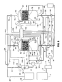
- FIG. 7 is a diagrammatic view of the overall apparatus for filtering particulates from a process liquid according to the present invention.
- FIG. 8 is a diagrammatic view of the apparatus for filtering particulates from a process liquid utilizing dual filter housings connected in a parallel flow filtration system according to the present invention.
- FIG. 9 is a diagrammatic view of the apparatus for filtering particulates from a process liquid utilizing dual filter housings connected in a serial flow filtration system according to the present invention.
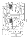
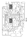
- FIG. 10 is a diagrammatic view of the filtration apparatus incorporating an intermediate hydroxyl ion-generating reactor which functions to precipitate dissolved metal ions prior to flowing through the filter bed to enable filtering precipitates thereof from a process liquid utilizing the dual filter, serial flow filtration system illustrated in FIG 9 .
- a central control system designated generally by the numeral 54 is used to monitor the sensors installed in the filtration system, and to turn "ON" and “OFF” all of the actuators (pumps and valves) required to operate the system.
- This control system may be operated either by manually actuated switches or by electronic switches activated by an embedded microprocessor. Although using a microprocessor makes the system somewhat more complex, it enables more efficient operation of the system as well as providing unattended operating capability during periods when no personnel are available to manually control the system.
- the process liquid to be filtered is withdrawn from a reservoir 2, connected by a conduit 3, to a pump priming chamber 4.
- the liquid may also be withdrawn directly from a process liquid stream.
- the use of the pump priming chamber 4 helps prolong the life of the primary liquid pump 7, by ensuring that the pump does not run “dry”. Running "dry” (i.e., run without liquid in the pump head), may damage the pump.
- valves As the liquid is removed from the pump priming chamber 4, through a conduit connecting the pump priming chamber 4 to the primary fluid pump 7, a partial vacuum is created in the pump priming chamber 4 and thus in the conduit 3 connecting the reservoir 2 to the priming chamber 4.
- the vacuum pulls process liquid from the reservoir and establishes a supply flow of the process liquid to the primary pump 7.
- valves may be manually actuated or electronically actuated, and preferably the latter.
- the filter bed 14 consists of small diameter super-buoyant particles having a specific gravity substantially lower than that of the liquid being filtered, and selected to be within a specific size range, nominally having a diameter between 0.1 micron and 25.4 mm.
- the size and material composition of the filter bed particles, as well as the bed volume and filtration area, are determined by the process liquid filtration requirements, including the size and nature of the particulates to be removed from the process liquid.
- the super-buoyant particles which compose the filter bed are typically formed from plastic, glass or ceramic materials, but in any event these particles must have a specific gravity less than one half that of the process liquid being filtered.
- the level of the process liquid rises in the housing.
- the filter bed 14 itself is prevented from rising any further in the housing 13, the process liquid continues to rise and flows through the filter bed 14 as it is pumped into the housing 13 by the primary pump 7.
- the bed support 16 thus also provides a final filtration barrier to the particulates carried in the liquid.
- the bed support 16 is nominally formed from a multi-layer "sandwich" ( FIG. 2 ) comprising a perforated metal plate 16a, and two or more layers of screen 16b and 16c.
- the "sandwich” may also comprise the aforementioned perforated metal plate 16a, with a single layer of screen 16b, and a layer of semi-permeable membrane or sintered permeable plastic or metal material 16d.
- the fine mesh screen 16c or membrane layer 16d is positioned at the lower face of the bed support 16 immediately next to the filter bed media.
- a medium mesh screen 16b is positioned in the center to provide structural support for the fine layer, and the perforated metal 16a is last and provides structural stiffening for the entire support assembly.
- the fine material, whether screen 16c or permeable membrane 16d, is preferably the layer that directly contacts the filter bed media 14.
- the other layers serve to provide structural support and enhance liquid flow through the bed support 16.
- This multiple layer design provides the strength necessary to retain the bed media 14 under working filtration pressures that may be as high, for example, as 5,171 x 10 5 Pa (75 psi) to 10,342 x 10 5 Pa (150 psi).
- a broader range may of course be utilized under appropriate conditions related to the type of media bed, the type and size of particulates sought to be filtered thereby and the optimum velocity flow of liquid through the system.
- contaminant particles are retained by the filter bed through one of two different mechanisms.
- the first mechanism occurs at the point where the process liquid flow first encounters the filter bed, surface filtration, the first mechanism. This mechanism occurs as the larger particulates are captured at the filter bed's lower surface, being unable to pass through the spaces between the particles, which make up the filter bed as the liquid flows up through the filter bed. As these larger particulates are captured at the lower surface of the filter bed, they form a crust on that surface.
- smaller particulates may be captured at the bottom surface of the filter, retained by the crust formed by the accumulation of larger particulates.
- this crust may by itself prevent the passage of some of the smaller particulates.
- Some of the smaller particulates may also pass through the crust on the filter bed's lower surface, penetrate the bed, and become trapped by the second mechanism, depth filtration. In this mechanism, these smaller particulates are captured and retained in the interstitial spaces in the filter bed between the super-buoyant filter media particles.
- the smallest particles depending on their size, the size of the bed particles, and the size of the openings in the bed support, may actually flow through the bed and exit the filter housing through the housing exit port 17 along with the out-flowing filtered process liquid.
- the process liquid After flowing through the filter bed support 16, the process liquid enters the top portion of the filter housing above the filter bed support structure and exits through the exit port 17. The liquid then flows through a connecting conduit 23 to a normally-open valve 24, another connecting conduit 26, and a flow sensor 27. Following the flow sensor 27, the liquid flows through an additional conduit 28 connecting to a clean process liquid reservoir 29 where the filtered liquid is stored. Also connected to this conduit 28 through an additional conduit 31, is normally-closed valve 32, and a final conduit 33 connected to a backwash reservoir 34.
- the backwash reservoir 34 provides a means of storing filtered process liquid for use in the backwash cycle that cleans the filter bed medium.
- the backwash reservoir 34 is open with respect to the atmosphere through vent 38 to prevent pressure build-up during filling as well as to prevent creation of a vacuum when liquid is removed for backwashing the filter.
- a liquid level sensor 36 in the backwash reservoir 34 is attached to the filter controller 54 via wire 109.
- the filter controller 54 opens valve 32 via wire 110 whenever the backwash reservoir liquid level is low, thus allowing filtered process liquid exiting the filter housing 13 to enter and fill the backwash reservoir 34.
- the level sensor 36 indicates to the controller 54 via wire 109 that the reservoir is full, and the controller 54 turns off valve 32 via wire 110 to stop liquid flow into the backwash reservoir 34.
- the flow sensor 27 measures the rate of flow of liquid exiting the filter bed. The signal from this sensor is transmitted to the filter controller 54 via wire 112. As the filter accumulates more and more particulates from the liquid stream, the resistance of the bed to liquid flow increases, and the flow of process liquid through the filter lessens (unless the flow of process liquid through the primary pump 7 is increased). At a critical point (defined by the filtration requirements for the process liquid), the flow measured by flow sensor 27 is low enough that the filter must be regenerated by a backwashing process to regain its filtration capacity. This point is identified by having the control system 54 monitor the output of flow sensor 27 via wire 112.
- the normally-open valves 9, 24 in the filter inflow line and in the filter outflow line, respectively, are closed by the controller via wires 103 and 111, respectively, to prevent continued flow of the liquid through the filter.
- the normally-closed liquid drain valve 46 and the normally-closed atmospheric vent valve 22 are opened by the controller 54 via wires 102 and 108, respectively. With these valves open, "dirty" liquid drains from the filter housing into the collection reservoir 48 through conduit 11, valve 46 and conduit 47 by gravity flow under atmospheric pressure admitted into the housing through now open vent valve 22.
- the backwash spray delivered by nozzle(s) 44 washes adhering contaminant particulates off each filter particle of the filter bed 14. As this spray drains down through the remaining filter bed material, which is now in its lowermost position, carrying with it the collected contaminants, it accumulates in the bottom of the housing. As this drainage accumulates, the liquid level in the housing 13 rises, because of the continuing backwash process, and the super-buoyant media bed 14 (floating on top of the rising liquid) moves upward and past the backwash nozzle 44 which continues to spray clean liquid into the bed, thus continuously washing out the contaminant particulates, as illustrated in FIGS. 5A-5F .
- the fluid spray washes them out of the bed and causes them to sink to the bottom of the filter housing 13. Simultaneously, the super-buoyant filter bed particles, which are lighter than the process liquid, continue to float upwards on the rising liquid level in the filter housing 13.
- Level sensor 19 indicates to the controller 54 via wire 107 that the level of liquid in the housing 13 has risen to the appropriate level, and thus indicates that the entire filter bed has been washed in this manner.
- the filter controller 54 When the filter controller 54 receives information from the level sensor 19 that the liquid level is correct, the controller closes valve 42 via wire 105, opens drain valve 46 via wire 102, and thus causes the particulate-laden liquid to once more drain into the collection reservoir 48. This backwash sequence can then be repeated as necessary to ensure the highest level of cleanliness in the filter bed. Once backwashed, the clean filter medium, once again located in the lower end of the filter chamber, is again ready to filter particulates from the process liquid stream.
- the filtration process is again initiated by the controller 54 closing valves 46 and 22 via wires 102 and 108 opening the inlet valve 9 via wire 103 and the outlet valve 24 via wire 111, and pumping liquid from reservoir fluid pump 7 by actuating pump 7 via wire 101.
- the filter bed 14 again rises in the filter housing until it encounters the bed support 16.
- the filtration process then begins once again as the process liquid begins to flow upwards through the stabilized filter bed and the particulate contaminants begin to be captured by one of the two aforementioned filtration mechanisms.
- FIG. 8 In this second embodiment of this filtration system design, as illustrated in FIG. 8 , two filter housings (containing the same type of bed material) are connected in parallel with one another, so that the filtration system can continue to function without interruption while one of the two filters is being cleaned by backwashing.
- the two filters may be the same size or the primary filter may be larger than the secondary filter. In the former case, the two filters may share filtration effort equally, while in the latter case, the secondary filter serves only as a temporary filter to maintain filtration capability during the brief time required to backwash the primary filter.
- a central control system 54 with an embedded microprocessor is used to monitor the sensors installed in the filtration system, and to turn "ON” and “OFF” all of the actuators (pumps and valves) required to operate the system.
- this control system may also be operated manually, due to its increased complexity, the system is much more effectively controlled by an embedded microprocessor.
- the embedded microprocessor enables more efficient operation of the system as well as providing unattended operating capability for operation during periods when no personnel are available to manually control the system.
- the flow of the process liquid through the first or primary filter housing 13 follows the sequence described above for the system of FIG. 7 .
- the operational sequence applicable to the embodiment of FIG. 7 is included herein by reference rather than repeating the sequence.
- the normally-open valves 9 and 24 in the primary filter inflow line 11 and in the filter outflow line 23, respectively, are closed by the controller 54 via wires 103 and 111, respectively, to prevent continued flow of the liquid through the filter 13.
- the controller 54 opens normally-closed valves 57 and 73 via wires 115 and 119, respectively, to initiate the flow of process liquid through the secondary filter housing 62.
- the liquid is pumped by the primary pump 7 through conduits 8 and 56 to a now open (but normally-closed) valve 57 and into a connecting conduit 59 which attaches to the secondary filter housing 62 through the filter housing inlet 61.
- the secondary filter bed 63 is composed of the same particles as the primary filter bed 14.
- the particles in the secondary filter bed have the same specific size range, density and composition as the particles in the primary filter in order to meet the needs of the filtration process.
- the primary filter 13 may be larger than the secondary filter 62.
- the two filters may share filtration effort equally, while in the latter case, the secondary filter 62 serves only as a temporary filter to maintain filtration capability during the brief time required to backwash the primary filter 13.
- the filter bed 63 floating on the rising process liquid, reaches the bed support 64 near the top of the filter housing 62.
- this support retains the super-buoyant filter bed media, and also provides a final filtration barrier to the particulates carried in the liquid.
- the filter bed support 64 is nominally formed from the same kind of multi-layer "sandwich" ( FIGS. 2 , 3 ) described above.
- the senor When the level reaches a predetermined minimum value, the sensor signals the controller 54 through wire 109 to open valve 32 via wire 10. Additional clean liquid is then added to the backwash reservoir 34 through conduit 31, valve 32 and conduit 33. When the liquid level In the backwash reservoir 34 is returned to its normal level, the controller 54 closes valve 32 via wire 110 to stop the flow of liquid into the backwash reservoir 34.
- the backwash cycle for the primary filter housing 13 can be initiated.
- the normally-closed liquid drain valve 46 and the normally-closed atmospheric vent valve 22 are opened by the controller 54 via wires 102 and 108, respectively. With these valves open, dirty liquid drains from the primary filter housing 13 into the collection reservoir 48 through conduit 11, valve 46 and conduit 47.
- the controller re-initiates the filtration process in the primary filter housing 13 by closing valves 46, 22 and 57, via wires 102, 108 and 115, respectively, and by opening the inlet valve 9 and exit valve 24 via wires 103 and 111, and pumping liquid from the reservoir 2 via the primary liquid pump 7.
- the filter bed 14 rises in the housing and stabilizes when it encounters the bed support structure 16. The filtration process then begins once again as the process liquid begins to flow upward through the stabilized filter bed.
- the secondary filter 63 contained in the secondary filter housing 62 can be cleaned in the same manner by the backwashing process used for the primary filter.
- the process begins when the controller 54 opens the normally-closed liquid drain valve 58 and the normally-closed atmospheric vent valve 71 via wires 114 and 118. With these valves open, dirty liquid drains from filter housing 62 into the collection reservoir 48 through conduit 59, valve 58 and conduit 47.
- the liquid level in the housing 62 drops.
- the bed material (which is lighter than the process liquid, and thus still pressed against the bed support 64 as it floats on top of the process liquid) begins to descend in the filter housing 62 as it floats on the top of the receding liquid.
- the liquid level is allowed to descend until the top of the filter bed has fallen below the midpoint of the filter housing 62, as indicated to the controller 54 by the lower liquid level sensor 67 via wire 116. At this point, the controller closes drain valve 58 via wire 114 and the backwash spray process is initiated to clean the secondary filter bed.
- Level sensor 68 then indicates to the controller via wire 117 when the level of liquid in the housing 62 has risen to the appropriate point, thus indicating that the entire secondary filter bed has been washed of all contaminants and particulate matter.
- the controller 54 receives information from level sensor 68 via wire 117 that the liquid level is appropriate, the controller 54 opens the drain valve 58 via wire 114, and the particulate-laden liquid once more drains into the collection reservoir 48. This backwash sequence can then be repeated if necessary to ensure the highest level of cleanliness in the filter bed. The backwashed, clean filter medium 63 is then once again ready to filter particulates from the process liquid stream.
- two filter housings are connected in series with one another as illustrated in FIG. 9 to provide a filtration capability which is enhanced over that provided by a single filter.
- the super-buoyant filter bed material 14 in the first housing 13 is selected to filter out one or more specific components while the super-buoyant bed material 63 in the second housing 62 is selected to filter out one or more components different from those removed by the first filter.
- the bed material 14 in the first housing 13 is composed of coarser, larger diameter particles
- the filter bed material 63 in the second housing 62 is composed of finer, smaller diameter particles.
- This embodiment allows the first filter bed 14 to serve as a "coarse” filter for removing larger contaminant particles, and the second filter bed 63 to serve as a "fine” filter for removing smaller contaminant, particles which remain after the process liquid passes through the first bed 14.
- the process liquid to be filtered is withdrawn from the storage reservoir 2 through conduit 3 to the priming chamber 4, by the vacuum created by the pumping action of the primary pump 7.
- the liquid may also be withdrawn directly from a process liquid stream.
- the liquid then passes from priming chamber 4 through conduit 6 to the primary liquid pump 7, by which it is pumped through conduit 8, to the normally-open inlet valve 9, and into the connecting conduit 11.
- the liquid is pumped into the first filter housing 13 through the filter housing inlet 12 as previously described in relation to the FIG. 7 embodiment.
- the first filter bed 14 is composed of super-buoyant particles having a specific gravity less than one half that of the liquid being filtered, and selected to be within a specific size range, e.g., between 0.5 and 1.0 mm for a "coarse" filter.
- the size and composition of the filter bed particles, as well as the bed volume and filtration area are determined by the specific process liquid filtration requirements, including the size and nature of the particulates to be removed from the process liquid.
- the particles which compose the filter bed 14 are typically formed from plastic, glass or ceramic materials, but in any event these particles must have a specific gravity less than one half that of the specific gravity of the liquid being filtered.
- the level of the process liquid rises in the housing 13, the filter bed 14, which is floating on the rising process liquid, rises until it touches the bed support 16 adjacent the top of the filter housing.
- This support 16 retains the bed media 14, and prevents it both from rising any further and from flowing out of the filter housing along with the liquid being filtered.
- the bed support 16 also provides a final filtration barrier to the particulates carried in the liquid.
- the bed support 16 is nominally formed from a multi-layer sandwich ( FIG. 2 ), consisting of a perforated metal plate 16a, and two or more layers of screen 16b and 16c or alternatively ( FIG. 3 ), a layer of screen 16b and a layer of semi-permeable membrane or sintered permeable plastic or metal material 16d.
- the fine mesh screen 16c or membrane layer 16d is positioned adjacent the lower face of the bed support 16 immediately next to the filter bed media, a medium mesh screen 16b is positioned in the center to provide structural support for the fine layer, and the perforated metal plate 16a is last and provides structural stiffening.
- the fine material, whether screen 16c or permeable membrane 16d, is always the layer which directly contacts the top of the filter bed media 14.
- the other layers serve to provide structural support and enhance liquid flow through the bed support 16.
- This multiple layer design provides the strength necessary to retain the bed media under working filtration pressures that may be as high as 5,171 x 10 5 Pa (75 psi) to 10,342 x 10 5 Pa (150 psi), as previously described.
- contaminant particles are retained by the filter bed through two different mechanisms previously discussed.
- surface filtration the first mechanism, occurs. This mechanism occurs as the larger particulates are captured at the filter bed's lower surface, being unable to pass through the spaces between the particles that make up the filter bed as the liquid flows up through the bed. As these larger particulates are captured at the lower surface of the filter bed, they form a crust on that surface.
- smaller particulates may be captured at the bottom surface of the filter, retained by the crust formed by the accumulation of larger particulates.
- this crust may by itself prevent the passage of some of the smaller particulates.
- the smaller particulates may pass through the crust on the filter bed's lower surface, penetrate the bed, and become trapped by the second mechanism, namely, depth filtration, which captures and retains the smaller particles in the interstitial spaces between the filter media particles forming the bed.
- the smallest particulates will pass through the crust on the first filter bed's lower surface, the bed 14 itself and the bed restraint structure 16. These particulates will then flow with the liquid out of the filter through the filter housing outlet 17, conduit 82, the normally-open inlet valve 83 for the second filter bed, conduit 84, and finally into the second filter housing 62 through the housing inlet 61.
- the second filter bed 63 is composed of smaller diameter particles than the first filter bed 14 (e.g., 0.05 to 0.1 mm).
- the second filter bed particles are selected to be within the specific size range and composition to meet the specific needs of the filtration process as well as having a specific gravity lower than that of the liquid being filtered.
- the bed support is nominally formed from the same kind of multi-layer sandwich 16 previously discussed and illustrated in FIGS. 2 and 3 .
- the process liquid flows vertically upward through the filter bed 63, the smallest contaminant particles are retained by the second filter bed 63 through both surface filtration and depth filtration mechanisms.
- the liquid After flowing through the bed support 64, the liquid enters the top of the filter housing and exits through the exit port 66.
- the liquid then flows through a connecting conduit 86 to a normally-open valve 87, another connecting conduit 88, and a flow sensor 27. From the flow sensor 27, the liquid flows through an additional conduit 28 that connects to a clean process liquid reservoir 29. Also connected to this conduit 28 through an additional conduit 31, normally-closed valve 32, and final conduit 33, is the backwash reservoir 34.
- the sensor signals the controller 54 via wire 109 and the controller adds clean liquid to the reservoir 34 by opening normally-closed valve 32 via wire 110.
- the level sensor 36 signals the controller 54 via wire 109 and the controller closes valve 32 via wire 110 to stop the flow of liquid into the reservoir 34.
- the backwash process in this embodiment is to clean each bed individually, routing the dirty liquid from both filters into the collection tank 48.
- the controller 54 closes the normally-open valves 9, 83 in the first filter inflow line 11, in the second filter inflow line 82, and valve 87, in the filter outflow line 86 via wires 103, 123 and 127, respectively, to prevent continued flow of the liquid through the filters.
- the controller 54 opens the normally-closed liquid drain valve 46 and the normally-closed atmosphere vent valves 22 via wires 102 and 111. With these valves 46, 22 open, dirty liquid drains from the first filter housing 13 into the collection reservoir 48 through conduit 11, valve 46 and conduit 47.
- the bed material 14 (which has a specific gravity less than one half that of the process fluid, and thus is still pressed against the retaining screen 16 as it floats on top of the process liquid) begins to descend in the filter housing 13 as it floats on the top of the receding liquid.
- the liquid level is allowed to recede until the top of the filter bed has descended below the midpoint of the filter housing, which fact is indicated to the controller 54 by the lower liquid level sensor 18 via wire 106. At this point, the controller 54 closes the drain valve 46 via wire 102 and the backwash process is initiated to clean the filter bed 14.
- the liquid spray washes them out of the bed and causes them to sink to the bottom of the filter housing.
- the filter bed particles which are lighter than the process liquid, continue to float upwards on the rising liquid level in the filter housing.
- the backwash spray is continued until the entire bed has risen above the nozzle, allowing all of the bed particles to be cleansed by the spray of clean liquid emitted by the nozzle 44.
- Level sensor 19 indicates to the controller 54 through wire 107 that the level of liquid in the housing 13 has risen to the highest appropriate level, thus indicating that the entire bed has been washed in this fashion and that the filter bed now is positioned in the top portion of the filter housing above the body of contaminated liquid.
- the filter controller When the filter controller receives the signal from level sensor 19 that the level is appropriate, the controller 54 opens drain valve 46 via wire 102, and the particulate-laden contaminated liquid drains into the collection reservoir 48. Such draining may be effected by gravity induced flow, or a suction pump or siphon tube may be utilized to totally drain the contaminated liquid in less than one minute, causing the filter bed to descend in the housing as the contaminated liquid recedes.
- This backwash sequence can then be repeated as necessary to ensure the highest level of cleanliness in the filter bed.
- the controller 54 closes normally-closed valves 22 and 46 via wires 111 and 102. Once backwashed, the clean filter medium is then again ready to filter particulates from the process liquid stream.
- the controller 54 keeps the normally-open valves in the filter inflow line 83 and in the filter outflow line 87 closed to prevent continued flow of the liquid through the filter.
- the controller 54 then opens the normally-closed liquid drain valve 91 and the normally-closed atmospheric vent valve 71 via wires 122 and 126. With these valves open, dirty liquid drains from filter housing 62 into the collection reservoir 48 through conduit 84, valve 91 and conduit 47. As the liquid from the secondary filter housing 62 drains into the collection reservoir 48, air enters the filter housing through valve 71 and conduit 69, and the liquid level in the housing drops.
- the bed material begins to descend in the filter housing 62 as it floats on the top of the receding liquid.
- the liquid level is allowed to fall until the top of the filter bed has descended below the midpoint of the filter housing, as indicated to the controller 54 by the lower liquid level sensor 67 via wire 124.
- the controller closes drain valve 91 via wire 122 and the backwash process is initiated to clean the filter bed.
- the backwash spray is continued until the entire bed has risen above the nozzle, allowing all of the bed particles to be cleansed by the spray of clean liquid emitted by the nozzle 78.
- Level sensor 68 indicates to the controller 54 through wire 125 that the level of liquid in the housing 62 has risen to the appropriate level, thus indicating that the entire bed has been washed in this fashion and now lies above the contaminated body of liquid.
- the filter controller 54 receives information from the level sensor 68 that the level of the contaminated liquid is appropriate, it opens drain valve 91 via wire 122, and all the particulate-laden liquid once more drains into the collection reservoir 48. This backwash sequence can then be repeated as necessary to ensure the highest level of cleanliness in the filter bed. The backwashed, clean filter medium is then again ready to filter particulates from the process liquid stream.
- the filtration process is again initiated when the controller 54 closes valves 91 and 71 via wires 122 and 126, opens the inlet valves 9 and 83 and exit valve 87 via wires 103, 123 and 127, respectively, and pumps liquid from the reservoir 2 via the primary fluid pump 7.
- the filter beds 14, 63 rise in the housings and stabilize when they encounter their respective filter bed restraint structures 16, 64.
- the filtration process then begins once again as the process liquid begins to flow upward through the stabilized filter beds.
- two filter housings 13 and 62 are arranged in series as described above with respect to FIG. 9 , and function by a unique method of chemical precipitation of dissolved, ionized metals in the aqueous solutions, followed by filtering of and removal of the precipitated particulates from the process liquid with a particulate filter as previously discussed.
- This is in contrast to dissolved metals conventionally precipitated in a liquid containing them by the direct addition of basic solutions (e.g., lime, sodium hydroxide, potassium hydroxide), which provide the required hydroxyl ions for initiation of the precipitation reaction.
- the advantage of the metals removal system described herein, in contrast to the conventional method described above, is that no basic solutions need be added to cause the precipitation. Instead, the hydroxyl ions are generated directly in the process liquid by pumping the liquid through an ultraviolet radiation reactor. This ultraviolet radiation forms hydroxyl ions in the metal-containing aqueous solution. These hydroxyl ions chemically combine with the ionized metals and cause them to precipitate and form particulates. These particulates are then removed from the aqueous solution by the filter bed filtration embodiments described herein.
- FIG. 10 A diagram of a system to effect this type of precipitation is presented in FIG. 10 .
- the diagram presented in this figure illustrates a pair of filter beds connected in series as described above and illustrated in FIG. 9 .
- an ultraviolet reactor 191 has been added to the system to process aqueous solution exiting from the first (coarse) filter housing 13.
- the structure and operation of the system of FIG. 10 is in all respects similar to the structure and operation of the system illustrated in FIG. 9 and described hereinabove. Accordingly, in the interest of brevity in this description, the operation of the system of FIG. 10 will not be described in detail and the description of the system illustrated in FIG. 9 is incorporated herein by reference.
- the aqueous process liquid then flows through an ultraviolet (UV) exposure reactor 191, where it is exposed to a high flux of UV radiation.
- UV radiation induces the formation of hydroxyl ions in the liquid, which subsequently combine with the ionized metals in the solution to form insoluble precipitate particles.
- the liquid then flows out of the UV exposure reactor 191, through the normally-open inlet valve 83 for the second filter bed, conduit 84, and into the second filter housing 62 through the housing inlet 61.
- the process liquid, now bearing the insoluble precipitated particles passes upward through the filter bed 63 in the second filter housing 62 as previously described.
Landscapes
- Chemical & Material Sciences (AREA)
- Chemical Kinetics & Catalysis (AREA)
- Life Sciences & Earth Sciences (AREA)
- Hydrology & Water Resources (AREA)
- Engineering & Computer Science (AREA)
- Environmental & Geological Engineering (AREA)
- Water Supply & Treatment (AREA)
- Organic Chemistry (AREA)
- Filtering Materials (AREA)
- Filtration Of Liquid (AREA)
- Physical Water Treatments (AREA)
- External Artificial Organs (AREA)
Claims (22)
- Prozessflüssigkeits-Filtervorrichtung, die ein Filterbett zum Entfernen von Schwebeteilchen aus einer Prozessflüssigkeit mit einer vorgegebenen relativen Dichte verwendet, mit:einer Pumpe, die einen Prozessfluid-Druck so bereitstellt, dass die Prozessflüssigkeit durch das Filterbett fließen kann;einer Filterkammer, die eine Einlassöffnung zum Aufnehmen der mit den Schwebeteilchen beladenen Prozessflüssigkeit und eine Auslassöffnung zum Ablassen einer filtrierten Prozessflüssigkeit aus der Filterkammer hat, wobei das Filterbett in der Filterkammer aus superschwimmfähigen Teilchen besteht, die eine relative Dichte haben, die kleiner als die Hälfte der vorgegebenen relativen Dichte der Prozessflüssigkeit ist;einem Bett-Träger, der so eingerichtet ist, dass er die superschwimmfähigen Teilchen zurückhält und den Prozessfluid-Druck aushält, der erforderlich ist, um die Prozessflüssigkeit mit dem Druck durch das Filterbett zu befördern;einem Rückspülsystem, das so wirkt, dass es Verunreinigungen aus den superschwimmfähigen Teilchen entfernt, und das mindestens eine Sprühdüse hat, die unter dem Bett-Träger angeordnet ist; undMittel zum Verbinden der mindestens einen Rückspül-Sprühdüse mit der Auslassöffnung der Filterkammer, um filtrierte Prozessflüssigkeit aus der Filterkammer zu der mindestens einen Rückspül-Sprühdüse zu befördern, wobei die mindestens eine Sprühdüse so in der Filterkammer angebracht ist, dass sie saubere filtrierte Prozessflüssigkeit nach unten sprüht.
- Filtervorrichtung nach Anspruch 1, dadurch gekennzeichnet, dass die superschwimmfähigen Filterbett-Teilchen locker verdichtet sind und eine Mehrheit ihrer Masse auf der zu filtrierenden Prozessflüssigkeit aufschwimmt.
- Filtervorrichtung nach Anspruch 2, dadurch gekennzeichnet, dass die Masse der superschwimmfähigen Filterteilchen so locker verdichtet ist, dass ein Rückspülen des Filterbetts ermöglicht wird, wenn die Masse der Filterteilchen auf einem Körper der Prozessflüssigkeit aufschwimmt.
- Filtervorrichtung nach Anspruch 3, dadurch gekennzeichnet, dass sich das Volumen der Masse der superschwimmfähigen Teilchen während des Rückspülens von 10 bis 30% ausdehnt, um dadurch eingefangene Schwebeteilchen zu befreien und sie aus dem Filterbett herauszuwaschen.
- Filtervorrichtung nach Anspruch 1, dadurch gekennzeichnet, dass die superschwimmfähigen Filterbett-Teilchen aus der Gruppe Kunststoff, Glas oder Keramik ausgewählt sind.
- Filtervorrichtung nach Anspruch 1, dadurch gekennzeichnet, dass sie einen UV-Reaktor aufweist.
- Filtervorrichtung nach Anspruch 1, dadurch gekennzeichnet, dass die Prozessflüssigkeit Wasser oder eine Prozessflüssigkeit auf der Basis von Wasser ist und die superschwimmfähigen Teilchen hydrophobe superschwimmfähige Teilchen sind.
- Filtervorrichtung nach Anspruch 1, dadurch gekennzeichnet, dass die superschwimmfähigen Teilchen kugelförmige Teilchen sind.
- Filtervorrichtung nach Anspruch 1, dadurch gekennzeichnet, dass der Bett-Träger ein mehrschichtiger Träger mit einem Lochblech und zwei oder mehr Siebschichten ist.
- Filtervorrichtung nach Anspruch 1, dadurch gekennzeichnet, dass der Bett-Träger ein mehrschichtiger Träger mit einem Lochblech, einer Siebschicht und einer Schicht aus einem halbdurchlässigen Material ist.
- Filtervorrichtung nach Anspruch 1, dadurch gekennzeichnet, dass die superschwimmfähigen Teilchen so gewählt sind, dass sie eine spezifische Größe in dem Bereich von 0,1 µm und 1,0 mm für ein feineres Filter haben.
- Flüssigkeitsfiltervorrichtung nach Anspruch 1, dadurch gekennzeichnet, dass ein Vorratsbehälter vorgesehen ist, der eine Einlassöffnung zum selektiven Aufnehmen von filtrierter Prozessflüssigkeit aus der Filterkammer und eine Auslassöffnung zum selektiven Ablassen von filtrierter Prozessflüssigkeit zurück in die Filterkammer hat, um das zusammengesetzte Filterbett rückzuspülen, um daraus Schwebeteilchen zu entfernen.
- Flüssigkeitsfiltervorrichtung nach Anspruch 12, dadurch gekennzeichnet, dass ein Vorratsbehälter vorgesehen ist, der mit der Einlassöffnung der Filterkammer verbunden ist, um Prozessflüssigkeit, die mit Schwebeteilchen verunreinigt ist, selektiv aus der Filterkammer zu sammeln, nachdem das zusammengesetzte Filterbett rückgespült worden ist, um die Schwebeteilchen zu entfernen.
- Flüssigkeitsfiltervorrichtung nach Anspruch 1, dadurch gekennzeichnet, dass Steuermittel vorgesehen sind, die selektiv so betreibbar sind, dass sie den Transport von mit Schwebeteilchen verunreinigter Prozessflüssigkeit zu und von der Filterkammer steuern und das Ablassen von filtrierter Prozessflüssigkeit aus der Filterkammer steuern.
- Filtervorrichtung nach Anspruch 1, dadurch gekennzeichnet, dass die superschwimmfähigen Teilchen so gewählt sind, dass sie eine spezifische Größe in dem Bereich von 0,1 µm und 25,4 mm haben.
- Flüssigkeitsfiltervorrichtung nach Anspruch 1, dadurch gekennzeichnet, dass die Filterkammer mit einem normalerweise geschlossenen Lüftungsrohr versehen ist, das das Innere der Filterkammer mit der Atmosphäre verbindet und selektiv geöffnet wird, wenn Prozessflüssigkeit, die mit Schwebeteilchen verunreinigt ist, aus der Filterkammer abgelassen wird, nachdem das zusammengesetzte Filterbett rückgespült worden ist, um verunreinigende Schwebeteilchen daraus zu entfernen.
- Flüssigkeitsfiltervorrichtung nach Anspruch 1, dadurch gekennzeichnet, dass Mittel, die in die Mittel integriert sind, die den mindestens einen Sprühkopf mit der Filterkammer verbinden, selektiv so betreibbar sind, dass sie die Beförderung der filtrierten Prozessflüssigkeit zu dem mindestens einen Sprühkopf initiieren, wenn das superschwimmfähige Filterbett so mit Schwebeteilchen zugesetzt ist, dass die Fließgeschwindigkeit der filtrierten Prozessflüssigkeit unter eine gewählte festgelegte Fließgeschwindigkeit absinkt, wodurch das Filterbett rückgespült wird, um daraus die Schwebeteilchen zu entfernen, wobei die Mittel, die auf die verringerte Fließgeschwindigkeit von der Filterkammer reagieren, Folgendes umfassen: einen Sensor, der die Fließgeschwindigkeit misst; eine Vielzahl von Magnetventilen; einen Vorratsbehälter für filtrierte Prozessflüssigkeit; eine Pumpe und ein elektronisches Steuersystem, das den Sensor, die Ventile, den Vorratsbehälter und die Pumpe miteinander verbindet.
- Flüssigkeitsfiltervorrichtung nach Anspruch 1, dadurch gekennzeichnet, dass zwei Filterkammern vorgesehen sind, die in einer Parallelstrom-Filtersystemkonfiguration verbunden sind.
- Flüssigkeitsfiltervorrichtung nach Anspruch 18, dadurch gekennzeichnet, dass Steuermittel vorgesehen sind, die so betreibbar sind, dass sie eine Filterkammer im Filterbetrieb halten, während das Filterbett der anderen Filterkammer rückgespült wird, wodurch die mit Schwebeteilchen verunreinigte Prozessflüssigkeit kontinuierlich ohne Unterbrechung filtriert werden kann.
- Flüssigkeitsfiltervorrichtung nach Anspruch 17, dadurch gekennzeichnet, dass
zwei Filterkammern vorgesehen sind, die in einer Parallelstrom-Filtersystemkonfiguration verbunden sind, und
das elektronische Steuersystem einen eingebetteten Mikroprozessor aufweist, der so betreibbar ist, dass er die Sensoren überwacht und alle Pumpen und Ventile, die erforderlich sind, um die Vorrichtung mit den beiden Filterkammern in Betrieb zu setzen, rechtzeitig ein- und ausschaltet. - Flüssigkeitsfiltervorrichtung nach Anspruch 1, dadurch gekennzeichnet, dass zwei Filterkammern vorgesehen sind, die in einer Reihenstrom-Filtersystemkonfiguration verbunden sind, wobei eine erste der Filterkammern die primäre Filterkammer ist und eine zweite der Filterkammern die sekundäre Filterkammer ist.
- Flüssigkeitsfiltervorrichtung nach Anspruch 21, dadurch gekennzeichnet, dass
die Auslassöffnung der primären Filterkammer mit der Einlassöffnung der sekundären Filterkammer verbunden ist, die Auslassöffnung der sekundären Filterkammer selektiv so verbunden ist, dass sie der primären und der sekundären Kammer Prozessflüssigkeit zuführt, um ein Rückspülen der zusammengesetzten Filterbetten in den beiden Kammern zu bewirken, und
ein elektronisches Steuersystem vorgesehen ist, das die Reihenfluss-Filterkammern miteinander verbindet, wobei die Filterbetten in den reihengeschalteten Filtergehäusen aus Teilchen bestehen können, die so dimensioniert sind, dass sie grobe Schwebeteilchen aus der Prozessflüssigkeit filtrieren, die die erste Filterkammer passiert, und aus Teilchen bestehen können, die so dimensioniert sind, dass sie feinere Schwebeteilchen aus der Prozessflüssigkeit filtrieren, die in die sekundäre Filterkammer hineingelassen wird, um dadurch die Gesamtmenge von verunreinigenden Schwebeteilchen zu maximieren, die mit der Flüssigkeitsfiltervorrichtung entfernt werden.
Applications Claiming Priority (2)
| Application Number | Priority Date | Filing Date | Title |
|---|---|---|---|
| US10/634,595 US7270745B2 (en) | 2003-08-04 | 2003-08-04 | Liquid filtration apparatus embodying super-buoyant filtration particles |
| PCT/US2004/022303 WO2006025811A1 (en) | 2003-08-04 | 2004-08-02 | Liquid filtration apparatus and method embodying super-buoyant filtration particles |
Publications (3)
| Publication Number | Publication Date |
|---|---|
| EP1680362A1 EP1680362A1 (de) | 2006-07-19 |
| EP1680362A4 EP1680362A4 (de) | 2009-07-22 |
| EP1680362B1 true EP1680362B1 (de) | 2011-01-12 |
Family
ID=34116064
Family Applications (1)
| Application Number | Title | Priority Date | Filing Date |
|---|---|---|---|
| EP04778021A Expired - Lifetime EP1680362B1 (de) | 2003-08-04 | 2004-08-02 | Flüssigkeitsfiltrationsapparatur und -verfahren mit superschwimmfähigen filtrationsteilchen |
Country Status (7)
| Country | Link |
|---|---|
| US (2) | US7270745B2 (de) |
| EP (1) | EP1680362B1 (de) |
| JP (1) | JP4922763B2 (de) |
| AT (1) | ATE494942T1 (de) |
| DE (1) | DE602004031035D1 (de) |
| ES (1) | ES2358742T3 (de) |
| WO (1) | WO2006025811A1 (de) |
Cited By (1)
| Publication number | Priority date | Publication date | Assignee | Title |
|---|---|---|---|---|
| CN106731058A (zh) * | 2016-12-08 | 2017-05-31 | 北京奥博水处理有限责任公司 | 一种不堵塞、免清洗、滤径可调过滤器 |
Families Citing this family (38)
| Publication number | Priority date | Publication date | Assignee | Title |
|---|---|---|---|---|
| US20100176050A1 (en) * | 2005-11-24 | 2010-07-15 | Bridgestone Corporation | Fluid purifying apparatus and filter housing |
| DE102008025168B4 (de) | 2008-05-26 | 2010-11-18 | Aquaworx Holding Ag | Vorrichtung zur Reinigung von Flüssigkeiten, insbesondere zur Reinigung von Ballastwasser |
| JP2010207800A (ja) * | 2009-02-16 | 2010-09-24 | Kuraray Co Ltd | ろ過ユニットおよびこれを備えたろ過装置 |
| US8246818B2 (en) * | 2009-04-24 | 2012-08-21 | Korzeniowski Jan A | Syphon filtration system |
| US8505742B2 (en) * | 2009-10-29 | 2013-08-13 | Velcon Filters, Llc | Perforated hexagon-hole tube support for synthetic screen separator |
| CN102596352A (zh) * | 2009-11-11 | 2012-07-18 | 诺狄克水产品公司 | 水及废水处理方法 |
| WO2012116039A2 (en) * | 2011-02-22 | 2012-08-30 | Suchanek Steven C | Zero-backwash liquid filter |
| US20130020266A1 (en) * | 2011-02-28 | 2013-01-24 | HTH Engineering & Equipment Company, LLC | Method and apparatus for water jet moving bed filtration system |
| US9731221B2 (en) | 2011-05-25 | 2017-08-15 | Cidra Corporate Services, Inc. | Apparatus having polymer surfaces having a siloxane functional group |
| AU2012337376B2 (en) * | 2011-05-25 | 2016-12-08 | Cidra Corporate Services Inc. | Mineral recovery in tailings using functionalized polymers |
| CN102284199B (zh) * | 2011-06-07 | 2013-09-11 | 珠海九通水务有限公司 | 自动化水处理反冲洗装置 |
| USD682398S1 (en) * | 2011-07-22 | 2013-05-14 | Akk Co., Ltd. | Water treatment media |
| CA2845996A1 (en) * | 2011-08-23 | 2013-02-28 | Pr Aqua Supplies Ltd. | Apparatus and methods for sequential treatments of process flows |
| EP2570167A1 (de) * | 2011-09-13 | 2013-03-20 | Bayer Intellectual Property GmbH | Gerät und Verfahren zur diskontinuierlichen Filtration |
| GB201115823D0 (en) | 2011-09-13 | 2011-10-26 | Novel Polymer Solutions Ltd | Mineral processing |
| US20130134100A1 (en) * | 2011-11-28 | 2013-05-30 | Celanese Acetate Llc | Compacted Filter Beds Comprising Non-Sintered, Buoyant Filter Media and Methods Relating Thereto |
| AU2013214751A1 (en) * | 2012-02-03 | 2014-09-11 | Filtration Technology Corporation | Filter cleaning system and method |
| USD678483S1 (en) * | 2012-08-09 | 2013-03-19 | Sun C. Barker | Disposable shower strainer |
| CN105979775B (zh) * | 2013-12-03 | 2020-01-14 | 比奥费什斯有限公司 | 机械生物过滤器 |
| CN104437293B (zh) * | 2014-12-05 | 2016-01-27 | 大连皆必喜机械有限公司 | 一种离型剂再生装置 |
| US11052338B2 (en) * | 2015-01-23 | 2021-07-06 | Kirk S. Morris | Systems and methods of filtering particulate matter from a fluid |
| GB201508392D0 (en) | 2015-05-15 | 2015-07-01 | Evolution Aqua Ltd | Mechanical filter element apparatus and method |
| WO2017161381A1 (en) | 2016-03-18 | 2017-09-21 | Schreiber, Llc | Improved methods for cleaning filtration system media |
| GB201608615D0 (en) * | 2016-05-16 | 2016-06-29 | Evolution Aqua Ltd | Filter apparatus and method |
| US11185800B2 (en) * | 2017-08-15 | 2021-11-30 | Conopco, Inc. | Apparatus and method for filtering aqueous liquid |
| GB2569780B (en) * | 2017-11-15 | 2022-06-01 | Evolution Aqua Ltd | Filter apparatus and method |
| US10913667B2 (en) | 2017-12-08 | 2021-02-09 | Westech Engineering, Inc. | Multi-media clarification systems and methods |
| CN108658162B (zh) * | 2018-05-17 | 2020-09-29 | 兖州煤业股份有限公司 | 采用硅藻土处理矿井水的一体化装置 |
| US11724214B2 (en) * | 2018-06-13 | 2023-08-15 | 2144811 Alberta Inc. | Method and apparatus for removal of particulate matter from a multiphase stream |
| CN110711414B (zh) * | 2018-07-12 | 2021-11-02 | 北京奥博水处理有限责任公司 | 一种双床介质过滤器 |
| CN108946994B (zh) * | 2018-08-14 | 2021-04-30 | 岳阳天河环保科技有限公司 | 一种多功能三级式污水处理装置 |
| RU2701932C1 (ru) | 2019-04-29 | 2019-10-02 | Общество с ограниченной ответственностью "МИРРИКО" | Способ очистки природных и сточных вод |
| USD946109S1 (en) | 2019-05-16 | 2022-03-15 | Evolution Aqua Limited | Water filter |
| USD968559S1 (en) | 2019-05-16 | 2022-11-01 | Evolution Aqua Limited | Water filter |
| US11272694B2 (en) | 2019-06-19 | 2022-03-15 | The Tru Shrimp Company | Aquaculture filtration systems |
| CN114873808A (zh) * | 2020-09-13 | 2022-08-09 | 陈志伟 | 一种具有支架及外置液泵的智能水处理装置及系统 |
| US11331616B2 (en) * | 2020-09-25 | 2022-05-17 | Mark Henderson | Pool filter assembly |
| US12208346B2 (en) | 2021-10-11 | 2025-01-28 | Mycelx Technologies Corporation | Backwashable media bed filtration system and drop in retrofit kit for same |
Family Cites Families (65)
| Publication number | Priority date | Publication date | Assignee | Title |
|---|---|---|---|---|
| US3067385A (en) * | 1959-08-24 | 1962-12-04 | Francis B Rykoskey | Oil monitor |
| US3067358A (en) | 1960-11-02 | 1962-12-04 | Ibm | Electro-erosion apparatus |
| US3469057A (en) * | 1965-02-15 | 1969-09-23 | Owens Corning Fiberglass Corp | Filter system for particulate matter |
| US3709362A (en) * | 1970-05-12 | 1973-01-09 | Ecodyne Corp | Self-backwashing filter apparatus |
| US3678240A (en) * | 1971-02-24 | 1972-07-18 | Gerald P Dietrick | Fluid handling system for electrical discharge machining equipment |
| JPS5326861B2 (de) * | 1974-10-25 | 1978-08-04 | ||
| US3962557A (en) * | 1975-01-30 | 1976-06-08 | Buck Homer G | Waste metal removal in E.D.M. machining |
| US4032300A (en) * | 1975-05-02 | 1977-06-28 | Shell Oil Company | Oxygen-containing gas distribution apparatus employed in fluidized bed regeneration of carbon-contaminated catalysts |
| JPS54147573A (en) * | 1978-05-10 | 1979-11-17 | Asahi Chem Ind Co Ltd | Segregating method |
| JPS54168678U (de) * | 1978-05-19 | 1979-11-28 | ||
| US4211656A (en) * | 1978-06-26 | 1980-07-08 | Cochrane John J | Liquid treating system |
| JPS5554006A (en) * | 1978-10-13 | 1980-04-21 | Nippon Paint Co Ltd | Suspension clarifying treatment apparatus |
| US4387286A (en) * | 1980-03-26 | 1983-06-07 | Inoue-Japax Research Incorporated | Apparatus for controlling splashes and purification of a machining liquid |
| JPS56163839A (en) * | 1980-05-15 | 1981-12-16 | Inoue Japax Res Inc | Electric discharge machining apparatus |
| US4743382A (en) * | 1980-08-06 | 1988-05-10 | The State Of Oregon Acting By And Through The State Board Of Higher Education On Behalf Of Oregon State University | Method and apparatus for separating suspended solids from liquids |
| DE3032882A1 (de) * | 1980-09-01 | 1982-04-15 | Linde Ag, 6200 Wiesbaden | Verfahren und vorrichtung zur biologischen reinigung von abwasser |
| US4383920A (en) * | 1981-05-29 | 1983-05-17 | Ecolochem, Inc. | Mobile fluid purification system |
| US4454040A (en) * | 1982-09-30 | 1984-06-12 | Roberts Robert L | Filter |
| US4608181A (en) * | 1983-03-25 | 1986-08-26 | Neptune Microfloc, Inc. | Water filtration apparatus having upflow buoyant media filter and downflow nonbuoyant media filter |
| JPS6094194A (ja) * | 1983-10-25 | 1985-05-27 | Kurita Water Ind Ltd | 有機性廃水の処理装置 |
| JPS60112313A (ja) * | 1983-11-24 | 1985-06-18 | Hitachi Ltd | 集積化波形変換回路 |
| DD241406B1 (de) * | 1985-10-03 | 1989-04-19 | Projekt Wasserwirtschaft Veb | Duesenbodenloser rieselfilmreaktor zur kontinuierlichen eliminierung geloester wasserinhaltsstoffe |
| JPS6352928A (ja) * | 1986-08-20 | 1988-03-07 | Toshiba Ceramics Co Ltd | 放電加工装置 |
| FR2611529A1 (fr) * | 1987-02-23 | 1988-09-09 | Degremont Sa | Appareil de filtration et procede de nettoyage d'un tel appareil |
| US4883083A (en) * | 1987-05-05 | 1989-11-28 | Donaldson Company, Inc. | Relief valve assembly; piston member from same and filter head assembly incorporating same |
| JPS63315108A (ja) * | 1987-06-15 | 1988-12-22 | Akua Giken Kk | 濾層の上方に浮動粒体物充填層を設けた濾過槽 |
| US4747945A (en) * | 1987-07-14 | 1988-05-31 | Culligan International Company | Lightweight media depth filter |
| US4885083A (en) * | 1987-08-10 | 1989-12-05 | Banks James V | Single chamber filter vessel |
| US4865734A (en) * | 1988-03-25 | 1989-09-12 | Schulz Christopher R | Buoyant coarse media flocculator |
| CA1327542C (en) * | 1988-03-25 | 1994-03-08 | Christopher R. Schulz | Buoyant coarse media flocculator |
| JPH02198720A (ja) * | 1988-10-03 | 1990-08-07 | Mitsubishi Electric Corp | 放電加工装置 |
| US5030353A (en) * | 1989-01-13 | 1991-07-09 | Stuth William L | Secondary sewage treatment system |
| JPH0736919B2 (ja) * | 1990-06-13 | 1995-04-26 | 勝利 大島 | 有機性廃液の浄化方法 |
| US5122287A (en) * | 1990-10-26 | 1992-06-16 | Hsiung Andrew K | Filtration system |
| US5126042A (en) * | 1991-10-31 | 1992-06-30 | Malone Ronald F | Floating media biofilter |
| US5178772A (en) * | 1991-11-15 | 1993-01-12 | Chemical Waste Management, Inc. | Process for destruction of metal complexes by ultraviolet irradiation |
| JPH05185325A (ja) * | 1992-01-10 | 1993-07-27 | Mitsubishi Electric Corp | 放電加工装置 |
| US5217607A (en) * | 1992-02-21 | 1993-06-08 | Diamond Water Systems, Inc. | Water decontamination system with filter, electrostatic treatment and UV radiation chamber |
| DE4214974A1 (de) * | 1992-05-06 | 1993-11-11 | Ultra Systems Gmbh Uv Oxidatio | Zerstörung von freien und komplexen Cyaniden, AOX, Mineralöl, Komplexbildnern, CSB, Nitrit, Chromat und Abtrennung von Metallen in Abwässern |
| US5232586A (en) * | 1992-09-25 | 1993-08-03 | Malone Ronald F | Floating media hourglass biofilter |
| GB2280124A (en) * | 1993-07-21 | 1995-01-25 | Pwt Projects Ltd | Granular bed filter |
| JPH0751687A (ja) * | 1993-08-20 | 1995-02-28 | Kurita Water Ind Ltd | 上向流式生物濾過装置 |
| US5434381A (en) * | 1993-09-13 | 1995-07-18 | T-Star Industrial Electronics, Inc. | Apparatus for filtering machining liquid of an electrical discharge machine |
| JPH07112193A (ja) * | 1993-10-19 | 1995-05-02 | Tonen Corp | 生物濾過床の逆洗方法 |
| US5573663A (en) * | 1994-01-10 | 1996-11-12 | Junius; John H. | Fluid filter using floating media |
| US5945005A (en) * | 1994-01-10 | 1999-08-31 | Junius; John H. | Fluid filter using floating media |
| JP3414480B2 (ja) * | 1994-02-21 | 2003-06-09 | 株式会社荏原製作所 | 浮上ろ過方法 |
| JPH07232008A (ja) * | 1994-02-21 | 1995-09-05 | Nittetsu Mining Co Ltd | 細粒セラミックス濾過装置 |
| US5662801A (en) * | 1994-05-09 | 1997-09-02 | Holland; Herbert W. | Method of removing organic compounds from air and water columns |
| JPH0824516A (ja) * | 1994-07-21 | 1996-01-30 | Toyo Eng Corp | 水処理設備 |
| JP2975276B2 (ja) * | 1994-11-16 | 1999-11-10 | ベスト工業株式会社 | 生物濾過装置用浮上濾材の洗浄方法 |
| CN1126629A (zh) * | 1995-02-13 | 1996-07-17 | 最佳工业株式会社 | 生物过滤装置用上浮过滤材料的洗净方法 |
| US5747311A (en) * | 1995-08-22 | 1998-05-05 | Microgen Corporation | Process for chemical modification of reactants by microbes |
| US5833867A (en) * | 1995-12-01 | 1998-11-10 | United States Filter Corporation | System and method for backwashing multiple filtration vessels |
| JPH09239374A (ja) * | 1996-03-08 | 1997-09-16 | Hoya Corp | ミセル電解液の処理方法 |
| US5932092A (en) * | 1996-06-13 | 1999-08-03 | Hawk; William D. | Filtering apparatus having positively buoyant and negatively buoyant particulate |
| JPH1028817A (ja) * | 1996-07-16 | 1998-02-03 | Tepitsukusu:Kk | 浮遊濾材の洗浄方法 |
| JPH10202014A (ja) * | 1997-01-27 | 1998-08-04 | Minoru Fukaya | 濾過装置 |
| US5770080A (en) * | 1997-04-23 | 1998-06-23 | Malone; Ronald F. | Air charged backwashing bioclarifier |
| US6015497A (en) * | 1997-12-17 | 2000-01-18 | Steen, Jr.; Albert Charles | Filtration system and method for removing biological wastes from aquaculture tanks |
| US6638422B1 (en) * | 1999-11-03 | 2003-10-28 | Steven H. Schwartzkopf | Liquid filtration apparatus and method embodying filtration particles having specific gravity less than liquid being filtered |
| JP2002336614A (ja) * | 2001-05-11 | 2002-11-26 | Hitachi Zosen Corp | 水族館等の水処理設備における海水濾過器の淡水・海水逆洗濾過システム |
| JP2002355689A (ja) * | 2001-05-31 | 2002-12-10 | Hitachi Zosen Corp | 閉鎖水域流入水の浄化装置 |
| JP2003093808A (ja) * | 2001-09-26 | 2003-04-02 | Masanobu Sakurai | 低圧式自己洗浄型ろ過装置 |
| JP2003144814A (ja) * | 2001-11-13 | 2003-05-20 | Ngk Insulators Ltd | 浮上ろ材の洗浄方法 |
-
2003
- 2003-08-04 US US10/634,595 patent/US7270745B2/en not_active Expired - Fee Related
-
2004
- 2004-08-02 EP EP04778021A patent/EP1680362B1/de not_active Expired - Lifetime
- 2004-08-02 DE DE602004031035T patent/DE602004031035D1/de not_active Expired - Lifetime
- 2004-08-02 ES ES04778021T patent/ES2358742T3/es not_active Expired - Lifetime
- 2004-08-02 WO PCT/US2004/022303 patent/WO2006025811A1/en not_active Ceased
- 2004-08-02 JP JP2006533828A patent/JP4922763B2/ja not_active Expired - Fee Related
- 2004-08-02 AT AT04778021T patent/ATE494942T1/de not_active IP Right Cessation
-
2005
- 2005-01-28 US US11/044,592 patent/US7270755B2/en not_active Expired - Fee Related
Cited By (1)
| Publication number | Priority date | Publication date | Assignee | Title |
|---|---|---|---|---|
| CN106731058A (zh) * | 2016-12-08 | 2017-05-31 | 北京奥博水处理有限责任公司 | 一种不堵塞、免清洗、滤径可调过滤器 |
Also Published As
| Publication number | Publication date |
|---|---|
| ES2358742T3 (es) | 2011-05-13 |
| EP1680362A1 (de) | 2006-07-19 |
| WO2006025811A1 (en) | 2006-03-09 |
| JP4922763B2 (ja) | 2012-04-25 |
| JP2007533429A (ja) | 2007-11-22 |
| US20050127011A1 (en) | 2005-06-16 |
| US20050029204A1 (en) | 2005-02-10 |
| DE602004031035D1 (de) | 2011-02-24 |
| ATE494942T1 (de) | 2011-01-15 |
| US7270755B2 (en) | 2007-09-18 |
| US7270745B2 (en) | 2007-09-18 |
| EP1680362A4 (de) | 2009-07-22 |
Similar Documents
| Publication | Publication Date | Title |
|---|---|---|
| US7270745B2 (en) | Liquid filtration apparatus embodying super-buoyant filtration particles | |
| US6638422B1 (en) | Liquid filtration apparatus and method embodying filtration particles having specific gravity less than liquid being filtered | |
| CN112154033B (zh) | 过滤系统中进行固体调理的系统和方法 | |
| US8012359B2 (en) | Filtration apparatus | |
| JP6049005B2 (ja) | ろ過装置、そのろ過方法及びろ材の逆洗方法 | |
| JPWO2014103854A1 (ja) | バラスト水処理装置およびバラスト水処理装置の逆洗浄方法 | |
| KR20040066002A (ko) | 여과장치 및 그것을 이용한 여과방법 | |
| KR20060049233A (ko) | 여과방법 및 여과장치 | |
| US7258784B2 (en) | Solid liquid filtration apparatus and method | |
| JP2007038205A (ja) | 濾過装置 | |
| JP4777857B2 (ja) | ろ過システム | |
| Bourgeous et al. | Performance Evaluation of a Cloth‐Media Disk Filter for Wastewater Reclamation | |
| JP4171248B2 (ja) | 浮上濾材を用いた濾過装置 | |
| JP2002035511A (ja) | 濾過装置 | |
| CN1010747B (zh) | 一种新型的漂浮滤池 | |
| JP2706080B2 (ja) | 濾過装置とその洗浄方法 | |
| GB2432130A (en) | Filtration apparatus | |
| JP4262568B2 (ja) | 油水分離装置 | |
| KR0142996B1 (ko) | 역 세척이 가능한 폐수의 여과 처리방법과 이에 사용되는 장치 | |
| US20090166277A1 (en) | Method of cleansing filtration media and system thereof | |
| JP3606449B2 (ja) | ろ過体の洗浄方法及び装置 | |
| US20040217066A1 (en) | Universal piping apparatus for use with a filtration device | |
| JPH0947604A (ja) | 浮上▲ろ▼材を使用する回分式上昇流▲ろ▼過装置 | |
| HK40045138B (en) | System and method of solids conditioning in a filtration system | |
| HK40045138A (en) | System and method of solids conditioning in a filtration system |
Legal Events
| Date | Code | Title | Description |
|---|---|---|---|
| PUAI | Public reference made under article 153(3) epc to a published international application that has entered the european phase |
Free format text: ORIGINAL CODE: 0009012 |
|
| AK | Designated contracting states |
Kind code of ref document: A1 Designated state(s): AT BE BG CH CY CZ DE DK EE ES FI FR GB GR HU IE IT LI LU MC NL PL PT RO SE SI SK TR |
|
| AX | Request for extension of the european patent |
Extension state: AL HR LT LV MK |
|
| 17P | Request for examination filed |
Effective date: 20060911 |
|
| RBV | Designated contracting states (corrected) |
Designated state(s): AT BE BG CH CY CZ DE DK EE ES FI FR GB GR HU IE IT LI LU MC NL PL PT RO SE SI SK TR |
|
| DAX | Request for extension of the european patent (deleted) | ||
| RIC1 | Information provided on ipc code assigned before grant |
Ipc: B01D 24/16 20060101AFI20090512BHEP Ipc: C02F 1/00 20060101ALI20090512BHEP Ipc: C02F 1/32 20060101ALI20090512BHEP |
|
| A4 | Supplementary search report drawn up and despatched |
Effective date: 20090624 |
|
| 17Q | First examination report despatched |
Effective date: 20091109 |
|
| GRAP | Despatch of communication of intention to grant a patent |
Free format text: ORIGINAL CODE: EPIDOSNIGR1 |
|
| GRAS | Grant fee paid |
Free format text: ORIGINAL CODE: EPIDOSNIGR3 |
|
| GRAA | (expected) grant |
Free format text: ORIGINAL CODE: 0009210 |
|
| AK | Designated contracting states |
Kind code of ref document: B1 Designated state(s): AT BE BG CH CY CZ DE DK EE ES FI FR GB GR HU IE IT LI LU MC NL PL PT RO SE SI SK TR |
|
| REG | Reference to a national code |
Ref country code: GB Ref legal event code: FG4D |
|
| REG | Reference to a national code |
Ref country code: CH Ref legal event code: EP |
|
| REG | Reference to a national code |
Ref country code: IE Ref legal event code: FG4D |
|
| REF | Corresponds to: |
Ref document number: 602004031035 Country of ref document: DE Date of ref document: 20110224 Kind code of ref document: P |
|
| REG | Reference to a national code |
Ref country code: DE Ref legal event code: R096 Ref document number: 602004031035 Country of ref document: DE Effective date: 20110224 |
|
| REG | Reference to a national code |
Ref country code: ES Ref legal event code: FG2A Ref document number: 2358742 Country of ref document: ES Kind code of ref document: T3 Effective date: 20110503 |
|
| REG | Reference to a national code |
Ref country code: NL Ref legal event code: VDEP Effective date: 20110112 |
|
| PG25 | Lapsed in a contracting state [announced via postgrant information from national office to epo] |
Ref country code: SE Free format text: LAPSE BECAUSE OF FAILURE TO SUBMIT A TRANSLATION OF THE DESCRIPTION OR TO PAY THE FEE WITHIN THE PRESCRIBED TIME-LIMIT Effective date: 20110112 Ref country code: GR Free format text: LAPSE BECAUSE OF FAILURE TO SUBMIT A TRANSLATION OF THE DESCRIPTION OR TO PAY THE FEE WITHIN THE PRESCRIBED TIME-LIMIT Effective date: 20110413 Ref country code: PT Free format text: LAPSE BECAUSE OF FAILURE TO SUBMIT A TRANSLATION OF THE DESCRIPTION OR TO PAY THE FEE WITHIN THE PRESCRIBED TIME-LIMIT Effective date: 20110512 |
|
| PG25 | Lapsed in a contracting state [announced via postgrant information from national office to epo] |
Ref country code: CY Free format text: LAPSE BECAUSE OF FAILURE TO SUBMIT A TRANSLATION OF THE DESCRIPTION OR TO PAY THE FEE WITHIN THE PRESCRIBED TIME-LIMIT Effective date: 20110112 Ref country code: FI Free format text: LAPSE BECAUSE OF FAILURE TO SUBMIT A TRANSLATION OF THE DESCRIPTION OR TO PAY THE FEE WITHIN THE PRESCRIBED TIME-LIMIT Effective date: 20110112 Ref country code: AT Free format text: LAPSE BECAUSE OF FAILURE TO SUBMIT A TRANSLATION OF THE DESCRIPTION OR TO PAY THE FEE WITHIN THE PRESCRIBED TIME-LIMIT Effective date: 20110112 Ref country code: SI Free format text: LAPSE BECAUSE OF FAILURE TO SUBMIT A TRANSLATION OF THE DESCRIPTION OR TO PAY THE FEE WITHIN THE PRESCRIBED TIME-LIMIT Effective date: 20110112 Ref country code: BG Free format text: LAPSE BECAUSE OF FAILURE TO SUBMIT A TRANSLATION OF THE DESCRIPTION OR TO PAY THE FEE WITHIN THE PRESCRIBED TIME-LIMIT Effective date: 20110412 Ref country code: PL Free format text: LAPSE BECAUSE OF FAILURE TO SUBMIT A TRANSLATION OF THE DESCRIPTION OR TO PAY THE FEE WITHIN THE PRESCRIBED TIME-LIMIT Effective date: 20110112 Ref country code: BE Free format text: LAPSE BECAUSE OF FAILURE TO SUBMIT A TRANSLATION OF THE DESCRIPTION OR TO PAY THE FEE WITHIN THE PRESCRIBED TIME-LIMIT Effective date: 20110112 Ref country code: NL Free format text: LAPSE BECAUSE OF FAILURE TO SUBMIT A TRANSLATION OF THE DESCRIPTION OR TO PAY THE FEE WITHIN THE PRESCRIBED TIME-LIMIT Effective date: 20110112 |
|
| PG25 | Lapsed in a contracting state [announced via postgrant information from national office to epo] |
Ref country code: DK Free format text: LAPSE BECAUSE OF FAILURE TO SUBMIT A TRANSLATION OF THE DESCRIPTION OR TO PAY THE FEE WITHIN THE PRESCRIBED TIME-LIMIT Effective date: 20110112 Ref country code: EE Free format text: LAPSE BECAUSE OF FAILURE TO SUBMIT A TRANSLATION OF THE DESCRIPTION OR TO PAY THE FEE WITHIN THE PRESCRIBED TIME-LIMIT Effective date: 20110112 |
|
| PLBE | No opposition filed within time limit |
Free format text: ORIGINAL CODE: 0009261 |
|
| STAA | Information on the status of an ep patent application or granted ep patent |
Free format text: STATUS: NO OPPOSITION FILED WITHIN TIME LIMIT |
|
| PG25 | Lapsed in a contracting state [announced via postgrant information from national office to epo] |
Ref country code: CZ Free format text: LAPSE BECAUSE OF FAILURE TO SUBMIT A TRANSLATION OF THE DESCRIPTION OR TO PAY THE FEE WITHIN THE PRESCRIBED TIME-LIMIT Effective date: 20110112 Ref country code: SK Free format text: LAPSE BECAUSE OF FAILURE TO SUBMIT A TRANSLATION OF THE DESCRIPTION OR TO PAY THE FEE WITHIN THE PRESCRIBED TIME-LIMIT Effective date: 20110112 Ref country code: RO Free format text: LAPSE BECAUSE OF FAILURE TO SUBMIT A TRANSLATION OF THE DESCRIPTION OR TO PAY THE FEE WITHIN THE PRESCRIBED TIME-LIMIT Effective date: 20110112 |
|
| 26N | No opposition filed |
Effective date: 20111013 |
|
| REG | Reference to a national code |
Ref country code: DE Ref legal event code: R097 Ref document number: 602004031035 Country of ref document: DE Effective date: 20111013 |
|
| PG25 | Lapsed in a contracting state [announced via postgrant information from national office to epo] |
Ref country code: MC Free format text: LAPSE BECAUSE OF NON-PAYMENT OF DUE FEES Effective date: 20110831 |
|
| REG | Reference to a national code |
Ref country code: IE Ref legal event code: MM4A |
|
| PG25 | Lapsed in a contracting state [announced via postgrant information from national office to epo] |
Ref country code: IE Free format text: LAPSE BECAUSE OF NON-PAYMENT OF DUE FEES Effective date: 20110802 |
|
| PG25 | Lapsed in a contracting state [announced via postgrant information from national office to epo] |
Ref country code: LU Free format text: LAPSE BECAUSE OF NON-PAYMENT OF DUE FEES Effective date: 20110802 |
|
| PG25 | Lapsed in a contracting state [announced via postgrant information from national office to epo] |
Ref country code: TR Free format text: LAPSE BECAUSE OF FAILURE TO SUBMIT A TRANSLATION OF THE DESCRIPTION OR TO PAY THE FEE WITHIN THE PRESCRIBED TIME-LIMIT Effective date: 20110112 |
|
| PG25 | Lapsed in a contracting state [announced via postgrant information from national office to epo] |
Ref country code: HU Free format text: LAPSE BECAUSE OF FAILURE TO SUBMIT A TRANSLATION OF THE DESCRIPTION OR TO PAY THE FEE WITHIN THE PRESCRIBED TIME-LIMIT Effective date: 20110112 |
|
| REG | Reference to a national code |
Ref country code: FR Ref legal event code: PLFP Year of fee payment: 13 |
|
| PGFP | Annual fee paid to national office [announced via postgrant information from national office to epo] |
Ref country code: IT Payment date: 20160831 Year of fee payment: 13 |
|
| REG | Reference to a national code |
Ref country code: FR Ref legal event code: PLFP Year of fee payment: 14 |
|
| PGFP | Annual fee paid to national office [announced via postgrant information from national office to epo] |
Ref country code: DE Payment date: 20170831 Year of fee payment: 14 Ref country code: CH Payment date: 20170817 Year of fee payment: 14 Ref country code: FR Payment date: 20170821 Year of fee payment: 14 Ref country code: ES Payment date: 20170912 Year of fee payment: 14 Ref country code: GB Payment date: 20170821 Year of fee payment: 14 |
|
| PG25 | Lapsed in a contracting state [announced via postgrant information from national office to epo] |
Ref country code: IT Free format text: LAPSE BECAUSE OF NON-PAYMENT OF DUE FEES Effective date: 20170802 |
|
| REG | Reference to a national code |
Ref country code: DE Ref legal event code: R119 Ref document number: 602004031035 Country of ref document: DE |
|
| REG | Reference to a national code |
Ref country code: CH Ref legal event code: PL |
|
| GBPC | Gb: european patent ceased through non-payment of renewal fee |
Effective date: 20180802 |
|
| PG25 | Lapsed in a contracting state [announced via postgrant information from national office to epo] |
Ref country code: CH Free format text: LAPSE BECAUSE OF NON-PAYMENT OF DUE FEES Effective date: 20180831 Ref country code: LI Free format text: LAPSE BECAUSE OF NON-PAYMENT OF DUE FEES Effective date: 20180831 |
|
| PG25 | Lapsed in a contracting state [announced via postgrant information from national office to epo] |
Ref country code: DE Free format text: LAPSE BECAUSE OF NON-PAYMENT OF DUE FEES Effective date: 20190301 |
|
| PG25 | Lapsed in a contracting state [announced via postgrant information from national office to epo] |
Ref country code: FR Free format text: LAPSE BECAUSE OF NON-PAYMENT OF DUE FEES Effective date: 20180831 |
|
| REG | Reference to a national code |
Ref country code: ES Ref legal event code: FD2A Effective date: 20190918 |
|
| PG25 | Lapsed in a contracting state [announced via postgrant information from national office to epo] |
Ref country code: ES Free format text: LAPSE BECAUSE OF NON-PAYMENT OF DUE FEES Effective date: 20180803 Ref country code: GB Free format text: LAPSE BECAUSE OF NON-PAYMENT OF DUE FEES Effective date: 20180802 |