EP1681006A2 - Système de chauffage d'eau pour lave-vaisselle avec tube d'immersion et turbulateur associé - Google Patents
Système de chauffage d'eau pour lave-vaisselle avec tube d'immersion et turbulateur associé Download PDFInfo
- Publication number
- EP1681006A2 EP1681006A2 EP05027705A EP05027705A EP1681006A2 EP 1681006 A2 EP1681006 A2 EP 1681006A2 EP 05027705 A EP05027705 A EP 05027705A EP 05027705 A EP05027705 A EP 05027705A EP 1681006 A2 EP1681006 A2 EP 1681006A2
- Authority
- EP
- European Patent Office
- Prior art keywords
- heat exchange
- water
- exchange tube
- turbulator
- warewash machine
- Prior art date
- Legal status (The legal status is an assumption and is not a legal conclusion. Google has not performed a legal analysis and makes no representation as to the accuracy of the status listed.)
- Withdrawn
Links
- XLYOFNOQVPJJNP-UHFFFAOYSA-N water Substances O XLYOFNOQVPJJNP-UHFFFAOYSA-N 0.000 title claims abstract description 79
- 238000010438 heat treatment Methods 0.000 title claims abstract description 32
- 238000007654 immersion Methods 0.000 title description 2
- 239000007789 gas Substances 0.000 claims abstract description 23
- 239000000567 combustion gas Substances 0.000 claims abstract description 14
- 239000000203 mixture Substances 0.000 claims abstract description 9
- 239000008236 heating water Substances 0.000 claims abstract description 4
- 229910001220 stainless steel Inorganic materials 0.000 claims description 2
- 239000010935 stainless steel Substances 0.000 claims description 2
- 238000005406 washing Methods 0.000 description 5
- 238000002485 combustion reaction Methods 0.000 description 3
- 239000000463 material Substances 0.000 description 3
- 238000013461 design Methods 0.000 description 2
- 239000004744 fabric Substances 0.000 description 2
- 238000000034 method Methods 0.000 description 2
- 239000007921 spray Substances 0.000 description 2
- RYGMFSIKBFXOCR-UHFFFAOYSA-N Copper Chemical compound [Cu] RYGMFSIKBFXOCR-UHFFFAOYSA-N 0.000 description 1
- 239000005708 Sodium hypochlorite Substances 0.000 description 1
- XAGFODPZIPBFFR-UHFFFAOYSA-N aluminium Chemical compound [Al] XAGFODPZIPBFFR-UHFFFAOYSA-N 0.000 description 1
- 229910052782 aluminium Inorganic materials 0.000 description 1
- 239000000919 ceramic Substances 0.000 description 1
- 238000004891 communication Methods 0.000 description 1
- 229910052802 copper Inorganic materials 0.000 description 1
- 239000010949 copper Substances 0.000 description 1
- 239000013505 freshwater Substances 0.000 description 1
- 238000003780 insertion Methods 0.000 description 1
- 230000037431 insertion Effects 0.000 description 1
- 239000007788 liquid Substances 0.000 description 1
- 238000004519 manufacturing process Methods 0.000 description 1
- 238000002844 melting Methods 0.000 description 1
- 230000008018 melting Effects 0.000 description 1
- 238000012986 modification Methods 0.000 description 1
- 230000004048 modification Effects 0.000 description 1
- 238000011012 sanitization Methods 0.000 description 1
- SUKJFIGYRHOWBL-UHFFFAOYSA-N sodium hypochlorite Chemical compound [Na+].Cl[O-] SUKJFIGYRHOWBL-UHFFFAOYSA-N 0.000 description 1
- 238000012546 transfer Methods 0.000 description 1
- 239000002759 woven fabric Substances 0.000 description 1
Images


Classifications
-
- F—MECHANICAL ENGINEERING; LIGHTING; HEATING; WEAPONS; BLASTING
- F24—HEATING; RANGES; VENTILATING
- F24H—FLUID HEATERS, e.g. WATER OR AIR HEATERS, HAVING HEAT-GENERATING MEANS, e.g. HEAT PUMPS, IN GENERAL
- F24H1/00—Water heaters, e.g. boilers, continuous-flow heaters or water-storage heaters
- F24H1/18—Water-storage heaters
- F24H1/20—Water-storage heaters with immersed heating elements, e.g. electric elements or furnace tubes
- F24H1/205—Water-storage heaters with immersed heating elements, e.g. electric elements or furnace tubes with furnace tubes
-
- A—HUMAN NECESSITIES
- A47—FURNITURE; DOMESTIC ARTICLES OR APPLIANCES; COFFEE MILLS; SPICE MILLS; SUCTION CLEANERS IN GENERAL
- A47L—DOMESTIC WASHING OR CLEANING; SUCTION CLEANERS IN GENERAL
- A47L15/00—Washing or rinsing machines for crockery or tableware
- A47L15/42—Details
- A47L15/4285—Water-heater arrangements
-
- F—MECHANICAL ENGINEERING; LIGHTING; HEATING; WEAPONS; BLASTING
- F24—HEATING; RANGES; VENTILATING
- F24H—FLUID HEATERS, e.g. WATER OR AIR HEATERS, HAVING HEAT-GENERATING MEANS, e.g. HEAT PUMPS, IN GENERAL
- F24H9/00—Details
- F24H9/0005—Details for water heaters
- F24H9/001—Guiding means
Definitions
- the present application relates to warewasher water heating systems and more particularly to a warewasher water heating system including an immersion tube with a turbulator disposed therein.
- warewashers vary significantly in their design and manner of use, but many include a water heating tank. Water may be recirculated from the tank through wash arms under pressure via a pump. In many cases, it is desirable that the temperature of the water be maintained at an approximate temperature of, e.g., about 150° F in a high-temperature machine (one using a fresh final rinse at 180-195° F) or, e.g., at about 140° F in a low-temperature machine (one utilizing a final rinse mixture of fresh water and sodium hypochlorite for sanitizing, also at about 140° F). Due to the high volume seen by many commercial warewashers, any increase in efficiency can result in substantial savings in operation costs over time.
- a warewash machine in an aspect, includes a housing at least in part defining a wash area.
- a water tank supplies water to the wash area and a water heating system is provided for heating water in the water tank.
- the water heating system includes a heat exchange tube immersed in water within the water tank and has an outer surface in a heat exchange relationship with the water.
- An infrared gas burner is at least partially disposed within the heat exchange tube for combusting an air/gas mixture and delivering combustion gases through the heat exchange tube.
- a turbulator is positioned within the heat exchange tube downstream of the infrared gas burner for introducing turbulence in the combustion gases traveling through the heat exchange tube.
- a method of increasing the efficiency of a water heating system for a warewash machine includes providing a first heating system configuration.
- the first heating system configuration includes a housing at least in part defining a wash area, a water tank for supplying water to the wash area, a water heating system for heating water in the water tank, the water heating system including a heat exchange tube within the water tank, and an infrared gas burner at least partially disposed within the heat exchange tube for combusting an air/gas mixture and delivering combustion gases through the heat exchange tube.
- the first heating system configuration has an efficiency during a water heating operation. The efficiency is increased by positioning a turbulator within the heat exchange tube downstream of the infrared gas burner for introducing turbulence in the combustion gases traveling through the heat exchange tube.
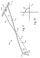
- FIG. 1 top, partial section view of an embodiment of a water heating system with a heat exchange tube shown in section;
- Fig. 2 is a perspective view of an embodiment of a turbulator
- Fig. 2A illustrates an angle between planar portions of the turbulator of Fig. 2;
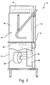
- Fig. 3 is a side, partial section view of an embodiment of a warewash machine including the water heating system of Fig. 1;
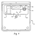
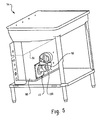
- Figs. 4 and 5 are top and perspective views of a base of the warewash machine of Fig. 3 with an outer cover removed;
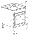
- Fig. 6 is a perspective view of an embodiment of a base of a warewash machine including a baffle box;
- Fig. 7 is a perspective view of the base of Fig. 6 with a sidewall of the baffle box removed.
- a water heating system 10 includes a heat exchange tube 14 and a heater 17 including a burner 22 disposed within the heat exchange tube.
- the heater 17 includes control connections 15 for connecting the heater to a control unit (not shown) for controlling operation of the heater and associated burner 22 during a heating operation.
- the heat exchange tube 14 is L-shaped including a first heat exchange portion 16, a gas inlet 24, a second heat exchange portion 18 and a gas outlet 26.
- a restricting portion 20 connects the first and second heat exchange portions 16, 18.
- the restricting portion 20 has an inner dimension to define a flow area that is less than that of the first and second heating portions 16 and 18, e.g., to induce or create back pressure for use during operation.
- back pressure can be introduced anywhere in the water heating system 10 between the burner 22 and the gas outlet 26.
- gas outlet 26 will typically connect with an exhaust stack and back pressure could also be induced at a location along the exhaust stack or path.
- a turbulator 30 is located within the heat exchange tube 14 downstream of the burner 22. The turbulator 30 introduces turbulence in the heated gases traveling through the heat exchange tube.
- a suitable heater 17 is an infrared (IR) heater including a gas-fired IR burner 22.
- IR burners typically have a hollow central permeable tube about which a sleeve 32 of woven ceramic fabric is provided.
- blower 34 When an air/gas mixture is introduced under pressure using blower 34 into the hollow tube, it flows outwardly through interstices of the woven fabric and, upon ignition of the mixture, forms the entire outer surface of the fabric to serve as an IR combustion surface 28.
- the pressure of the air/gas mixture and the back pressure built into the design are properly tuned, the flame will have a burning zone that is maintained at or near the combustion surface 28.
- turbulator 30 disposed within the second tube portion 18 is turbulator 30, which is represented by dashed lines to emphasize that turbulator 30 can be of any form suitable to introduce turbulence to the combustion gases flowing in the heat exchange tube 14. Turbulence is introduced to the combustion gas flow to force relatively hot combustion gases flowing near centerline L toward inner surface 44 of the heat exchange tube 14 (see arrows 19 of Fig. 1) and to mix the combustion gases within chamber 42, e.g., to provide a more uniform heating temperature during a heating operation. Turbulator 30 extends from an end 36 of the restricting portion 20 to outlet 26, which is formed by a flanged member 38 including flange 40.
- the flanged member 38 can be used to connect the heat exchange tube 14 to, for example, a flue or exhaust of a warewash machine.
- turbulator 30 may not extend to outlet 26 and may include, for example, a free end disposed within chamber 42.
- turbulator 30 has a maximum width W that is less than an inner dimension D of the second portion 18, e.g., to aid in assembly. In other embodiments, W may be about the same as D.
- Suitable materials for forming turbulator 30 include materials having a melting point high enough to withstand gas combustion temperatures, such as stainless steel, aluminum, copper, etc. Materials used to form the turbulator 30 may or may not have good thermal conductivity.
- an example of a turbulator 30 includes a first, relatively planar portion 46 and a second, relatively planar portion 48.
- First planar portion 46 and second planar portion 48 each form respective imaginary planes P 1 and P 2 that are disposed at an angle ⁇ (in some embodiments, between about zero and 180 degrees, such as about 45 degrees or greater, such as about 90 degrees) relative to each other (Fig. 2A).
- An angled or twisted portion 50 of varying angular relationship with respect to P 1 and P 2 connects the first and second planar portions 46 and 48.
- a stop tab 54 Connected at end 52 of the turbulator 30 is a stop tab 54. While in the illustrated embodiment each portion 46, 48 and 50 has somewhat smooth front and back faces, 62 and 64, the front and back faces can be ribbed, grooved, etc.
- the turbulator 30 is wedged into the second portion 18 through outlet 26, with the stop tab 54 sized to prevent the turbulator 30 from entering the first portion 16 of the heat exchange tube 14 and contacting burner 22.
- Stop tab 54 can also provide support for fixing turbulator 30 within the chamber 42 and maintaining spacing of the relatively planar portions 46, 48 from inner surface 46 of the heat exchange tube 14.
- Apertures 56 and 58 are located near ends 52 and 60 to aid in manufacture of the turbulator 30 by allowing for insertion of twisting members, such as rods, of a twisting device (not shown) to, for example, cold form a preform plate into the desired shape by twisting.
- the turbulator 30 can provide increased system efficiency at relatively low cost.
- Fig. 3 is a side view of a warewash machine 70 including a housing 72 atop a base 74, a moveable door 78 and a washing chamber 76 enclosed by the moveable door 78, while Figs. 4 and 5 show the water heating system 10 connected to a water tank 80 having a top opening that allows for communication with the washing chamber.
- this particular warewash machine embodiment is shown for illustrative purposes, it being understood that the heating system 10 can be useful with other warewash machine embodiments, such as conveyor-type warewash machines, or other types of warewash machines, for example, where detergent-laden wash water or rinse water is recirculated by a pump through one or more wash/rinse arms or other structures that spray liquid onto wares to be cleaned.
- warewash machine embodiments such as conveyor-type warewash machines, or other types of warewash machines, for example, where detergent-laden wash water or rinse water is recirculated by a pump through one or more wash/rinse arms or other structures that spray liquid onto wares to be cleaned.
- moveable door 78 encloses washing chamber 76 into which racks of wares are placed between an upper wash arm 82 and a lower wash arm 84, each of which arms are supplied with spray nozzles.
- Water is fed to the wash arms 82, 84 by a pump 86 which can include a screened water intake 88 and is passed through a conduit 90 to the arms.
- the water intake 88 is adjacent to and draws water through an opening 92 (Fig. 5) to water tank 80.
- Water fed to the wash arms 82, 84 is directed onto wares placed in the washing chamber 76 and the water drains back into the water tank 80 from the wares, enabling recirculation of water through the tank 80 as desired.
- water can be maintained at a predetermined fill level (e.g., as shown by dashed line 91) within the water tank 80 during a washing operation.
- a predetermined fill level e.g., as shown by dashed line 91
- the water tank 80 may be filled from either a separate water supply or through a conventionally-supplied water line.
- the level of water within the water tank 80 can be monitored, for example, using a float switch or electronic sensor (not shown), which can be operated to open and close a fill valve when the water reaches a desired level.
- a drain 94 is provided at the bottom of the water tank 80 and may be separate from or associated with a standpipe (not shown).
- the water level may be maintained within the water tank 80 such that the heat exchange tube 14 is completely submerged within the water.
- the heat exchange tube 14 extends generally horizontally within the water tank 80 with the first portion 16 connected to a front wall 96 of the water tank 80 and the second portion 18 connected to a rear wall 98 of the water tank.
- a gas supply conduit 100 (Figs. 1 and 5) extends from the blower 34 to the burner 22 for delivering the air/gas mixture to the burner.
- adding turbulator 30 to the heat exchange tube 14 of a warewasher can improve heating efficiency of the warewasher by about 2 percent (e.g., compared to the same warewasher without the turbulator 30).
- efficiency of a heating system was measured to be about 80 % without turbulator 30 and, after adding turbulator 30 by securing the turbulator within the heat exchange tube 14, the efficiency of the heating system was measured to be about 82 %.
- Efficiency of the heating system was determined by measuring the amount of heat units (BTU) and time necessary to increase the temperature of 110.6 pounds of water by 80° F in a pilot tank including baffle box 110 as shown in Figs. 6 and 7 using an IR heater having a BTU value UL listed at 25,000 and a heat exchange tube with a surface area of 286.9 sq inches. The following equation was used to calculate the efficiency and the results are summarized in Table I that follows.
- baffle plates 112 direct combustion gases exiting outlet 26 along a tortuous path for additional heating of the water through the sidewall of the water tank.
- the baffle box 110 includes an outlet 120 for connection to an exhaust stack.
- the turbulator could also be configured to provide flow restriction, which may induce back pressure in the heat exchange tube for more effective operation. Accordingly, other embodiments are contemplated.
Landscapes
- Engineering & Computer Science (AREA)
- Physics & Mathematics (AREA)
- Thermal Sciences (AREA)
- Chemical & Material Sciences (AREA)
- Combustion & Propulsion (AREA)
- Mechanical Engineering (AREA)
- General Engineering & Computer Science (AREA)
- Heat-Pump Type And Storage Water Heaters (AREA)
- Washing And Drying Of Tableware (AREA)
- Heat-Exchange Devices With Radiators And Conduit Assemblies (AREA)
- Instantaneous Water Boilers, Portable Hot-Water Supply Apparatuses, And Control Of Portable Hot-Water Supply Apparatuses (AREA)
Applications Claiming Priority (1)
| Application Number | Priority Date | Filing Date | Title |
|---|---|---|---|
| US11/036,423 US20060157092A1 (en) | 2005-01-14 | 2005-01-14 | Warewasher water heating system with immersion tube and associated turbulator |
Publications (2)
| Publication Number | Publication Date |
|---|---|
| EP1681006A2 true EP1681006A2 (fr) | 2006-07-19 |
| EP1681006A3 EP1681006A3 (fr) | 2007-06-20 |
Family
ID=36128359
Family Applications (1)
| Application Number | Title | Priority Date | Filing Date |
|---|---|---|---|
| EP05027705A Withdrawn EP1681006A3 (fr) | 2005-01-14 | 2005-12-17 | Système de chauffage d'eau pour lave-vaisselle avec tube d'immersion et turbulateur associé |
Country Status (5)
| Country | Link |
|---|---|
| US (1) | US20060157092A1 (fr) |
| EP (1) | EP1681006A3 (fr) |
| BR (1) | BRPI0600143A (fr) |
| CA (1) | CA2530836A1 (fr) |
| MX (1) | MXPA06000584A (fr) |
Families Citing this family (11)
| Publication number | Priority date | Publication date | Assignee | Title |
|---|---|---|---|---|
| RU2310256C2 (ru) * | 2005-12-16 | 2007-11-10 | Общество с ограниченной ответственностью "Национальная инновационная компания "Новые энергетические проекты" | Трубчатый элемент (варианты) для батарей высокотемпературных электрохимических устройств с тонкослойным твердым электролитом и способ его изготовления |
| US9839182B2 (en) | 2014-12-11 | 2017-12-12 | Ip Holdings, Llc | Horticulture lighting controller methods |
| USD848056S1 (en) | 2015-04-30 | 2019-05-07 | Hgci, Inc. | Horticulture lighting controller chassis |
| USD771792S1 (en) * | 2015-08-07 | 2016-11-15 | A. O. Smith Corporation | Air inlet damper |
| USD771233S1 (en) | 2015-08-07 | 2016-11-08 | A. O. Smith Corporation | Air inlet damper |
| USD779650S1 (en) * | 2015-08-07 | 2017-02-21 | A. O. Smith Corporation | Air inlet damper |
| USD771789S1 (en) * | 2015-08-07 | 2016-11-15 | A. O. Smith Corporation | Air inlet damper |
| USD771234S1 (en) * | 2015-08-07 | 2016-11-08 | A. O. Smith Corporation | Air inlet damper |
| USD771791S1 (en) * | 2015-08-07 | 2016-11-15 | A. O. Smith Corporation | Air inlet damper |
| USD771793S1 (en) * | 2015-08-07 | 2016-11-15 | A. O. Smith Corporation | Air inlet damper |
| USD771790S1 (en) * | 2015-08-07 | 2016-11-15 | A. O. Smith Corporation | Air inlet damper |
Family Cites Families (6)
| Publication number | Priority date | Publication date | Assignee | Title |
|---|---|---|---|---|
| US2558971A (en) * | 1945-09-17 | 1951-07-03 | Allan W Lundstrum | Water heater |
| US4492185A (en) * | 1981-10-05 | 1985-01-08 | Alzeta Corporation | High efficiency, reduced emissions water heater |
| US4510890A (en) * | 1983-04-11 | 1985-04-16 | Cowan Edwin J | Infrared water heater |
| EP0248629B1 (fr) * | 1986-06-04 | 1992-08-12 | Ambi-Rad Limited | Appareil de chauffage des locaux |
| US5368008A (en) * | 1992-10-09 | 1994-11-29 | Delaware Capital Formation, Inc. | Steamer apparatus |
| US5511570B1 (en) * | 1994-10-13 | 1997-08-26 | Stero Co | Warewasher employing infrared burner |
-
2005
- 2005-01-14 US US11/036,423 patent/US20060157092A1/en not_active Abandoned
- 2005-12-17 EP EP05027705A patent/EP1681006A3/fr not_active Withdrawn
- 2005-12-19 CA CA002530836A patent/CA2530836A1/fr not_active Abandoned
-
2006
- 2006-01-12 BR BRPI0600143-2A patent/BRPI0600143A/pt not_active Application Discontinuation
- 2006-01-13 MX MXPA06000584A patent/MXPA06000584A/es unknown
Also Published As
| Publication number | Publication date |
|---|---|
| EP1681006A3 (fr) | 2007-06-20 |
| US20060157092A1 (en) | 2006-07-20 |
| BRPI0600143A (pt) | 2006-09-19 |
| CA2530836A1 (fr) | 2006-07-14 |
| MXPA06000584A (es) | 2006-07-13 |
Similar Documents
| Publication | Publication Date | Title |
|---|---|---|
| US5642742A (en) | Warewasher tank heating system and controls therefor | |
| EP0239189B1 (fr) | Chauffe-eau/chaudière au gaz et leur brûleur | |
| EP1681006A2 (fr) | Système de chauffage d'eau pour lave-vaisselle avec tube d'immersion et turbulateur associé | |
| AU749964B2 (en) | Power burner type fuel-fired water heater with quick change manifold assembly | |
| US20130152876A1 (en) | Water heating system | |
| WO2019025633A1 (fr) | Appareil de chauffage pour véhicule de loisirs | |
| US20100170452A1 (en) | Water heating apparatus, especially for pools | |
| JPH0666489A (ja) | ガス燃焼式水ヒータ | |
| RU2470230C1 (ru) | Способ получения пара и устройство для его реализации | |
| KR960004764Y1 (ko) | 난방용 온수보일러 | |
| JP3713664B2 (ja) | 電気加熱式の業務用スチーマー | |
| US3982552A (en) | Thermal protection for dishwashing machine | |
| JP7063728B2 (ja) | 加熱調理装置、および加熱調理方法 | |
| CN108626777B (zh) | 一种生活热水恒温壁挂炉 | |
| CN210891801U (zh) | 一种具有储热功能的燃气节能灶 | |
| JPH0217340A (ja) | ガス燃焼式調理装置 | |
| CN217685224U (zh) | 一种燃气节能型灶台 | |
| JP6849220B2 (ja) | 洗浄乾燥装置 | |
| KR930001050Y1 (ko) | 온수 보일러 | |
| JP2019177043A (ja) | 加熱調理装置 | |
| KR200282397Y1 (ko) | 온수기를 겸한 온풍 발생기 | |
| JP2024068323A (ja) | 給湯器 | |
| JP2025145687A (ja) | 給湯器の製造方法及び給湯器 | |
| JP2025173361A (ja) | 食器洗浄機用ブースター | |
| AU2012201784B2 (en) | Water heating apparatus, especially for pools |
Legal Events
| Date | Code | Title | Description |
|---|---|---|---|
| PUAI | Public reference made under article 153(3) epc to a published international application that has entered the european phase |
Free format text: ORIGINAL CODE: 0009012 |
|
| 17P | Request for examination filed |
Effective date: 20051217 |
|
| AK | Designated contracting states |
Kind code of ref document: A2 Designated state(s): AT BE BG CH CY CZ DE DK EE ES FI FR GB GR HU IE IS IT LI LT LU LV MC NL PL PT RO SE SI SK TR |
|
| AX | Request for extension of the european patent |
Extension state: AL BA HR MK YU |
|
| PUAL | Search report despatched |
Free format text: ORIGINAL CODE: 0009013 |
|
| AK | Designated contracting states |
Kind code of ref document: A3 Designated state(s): AT BE BG CH CY CZ DE DK EE ES FI FR GB GR HU IE IS IT LI LT LU LV MC NL PL PT RO SE SI SK TR |
|
| AX | Request for extension of the european patent |
Extension state: AL BA HR MK YU |
|
| 17Q | First examination report despatched |
Effective date: 20070808 |
|
| AKX | Designation fees paid |
Designated state(s): DE FR GB IT |
|
| STAA | Information on the status of an ep patent application or granted ep patent |
Free format text: STATUS: THE APPLICATION IS DEEMED TO BE WITHDRAWN |
|
| 18D | Application deemed to be withdrawn |
Effective date: 20090228 |