EP1681202A2 - Feu de véhicule - Google Patents
Feu de véhicule Download PDFInfo
- Publication number
- EP1681202A2 EP1681202A2 EP06000252A EP06000252A EP1681202A2 EP 1681202 A2 EP1681202 A2 EP 1681202A2 EP 06000252 A EP06000252 A EP 06000252A EP 06000252 A EP06000252 A EP 06000252A EP 1681202 A2 EP1681202 A2 EP 1681202A2
- Authority
- EP
- European Patent Office
- Prior art keywords
- vehicle lamp
- lamp according
- circuit carrier
- sealing material
- lens
- Prior art date
- Legal status (The legal status is an assumption and is not a legal conclusion. Google has not performed a legal analysis and makes no representation as to the accuracy of the status listed.)
- Withdrawn
Links
- 239000003566 sealing material Substances 0.000 claims description 36
- 239000000463 material Substances 0.000 claims description 15
- 239000000758 substrate Substances 0.000 claims description 14
- 238000004382 potting Methods 0.000 claims description 12
- 239000004020 conductor Substances 0.000 claims description 9
- 150000001875 compounds Chemical class 0.000 claims description 4
- XAGFODPZIPBFFR-UHFFFAOYSA-N aluminium Chemical compound [Al] XAGFODPZIPBFFR-UHFFFAOYSA-N 0.000 claims description 3
- 229910052782 aluminium Inorganic materials 0.000 claims description 3
- 229920002725 thermoplastic elastomer Polymers 0.000 claims description 3
- 239000012815 thermoplastic material Substances 0.000 claims description 3
- 239000011810 insulating material Substances 0.000 claims 1
- 239000000565 sealant Substances 0.000 abstract description 2
- 239000010410 layer Substances 0.000 description 13
- 238000004873 anchoring Methods 0.000 description 6
- 239000011796 hollow space material Substances 0.000 description 5
- 238000005266 casting Methods 0.000 description 3
- 238000002347 injection Methods 0.000 description 3
- 239000007924 injection Substances 0.000 description 3
- 238000001746 injection moulding Methods 0.000 description 3
- 238000007789 sealing Methods 0.000 description 3
- 238000011161 development Methods 0.000 description 2
- 230000018109 developmental process Effects 0.000 description 2
- 239000011888 foil Substances 0.000 description 2
- 239000002356 single layer Substances 0.000 description 2
- 239000012780 transparent material Substances 0.000 description 2
- 230000001464 adherent effect Effects 0.000 description 1
- 238000004026 adhesive bonding Methods 0.000 description 1
- 239000002131 composite material Substances 0.000 description 1
- 230000001419 dependent effect Effects 0.000 description 1
- 239000013013 elastic material Substances 0.000 description 1
- 238000004519 manufacturing process Methods 0.000 description 1
- 239000000203 mixture Substances 0.000 description 1
- 238000005192 partition Methods 0.000 description 1
- 238000007711 solidification Methods 0.000 description 1
- 230000008023 solidification Effects 0.000 description 1
- 230000007704 transition Effects 0.000 description 1
Images


Classifications
-
- B—PERFORMING OPERATIONS; TRANSPORTING
- B60—VEHICLES IN GENERAL
- B60Q—ARRANGEMENT OF SIGNALLING OR LIGHTING DEVICES, THE MOUNTING OR SUPPORTING THEREOF OR CIRCUITS THEREFOR, FOR VEHICLES IN GENERAL
- B60Q1/00—Arrangement of optical signalling or lighting devices, the mounting or supporting thereof or circuits therefor
- B60Q1/26—Arrangement of optical signalling or lighting devices, the mounting or supporting thereof or circuits therefor the devices being primarily intended to indicate the vehicle, or parts thereof, or to give signals, to other traffic
- B60Q1/2696—Mounting of devices using LEDs
-
- B—PERFORMING OPERATIONS; TRANSPORTING
- B60—VEHICLES IN GENERAL
- B60Q—ARRANGEMENT OF SIGNALLING OR LIGHTING DEVICES, THE MOUNTING OR SUPPORTING THEREOF OR CIRCUITS THEREFOR, FOR VEHICLES IN GENERAL
- B60Q1/00—Arrangement of optical signalling or lighting devices, the mounting or supporting thereof or circuits therefor
- B60Q1/0088—Details of electrical connections
-
- F—MECHANICAL ENGINEERING; LIGHTING; HEATING; WEAPONS; BLASTING
- F21—LIGHTING
- F21S—NON-PORTABLE LIGHTING DEVICES; SYSTEMS THEREOF; VEHICLE LIGHTING DEVICES SPECIALLY ADAPTED FOR VEHICLE EXTERIORS
- F21S43/00—Signalling devices specially adapted for vehicle exteriors, e.g. brake lamps, direction indicator lights or reversing lights
- F21S43/10—Signalling devices specially adapted for vehicle exteriors, e.g. brake lamps, direction indicator lights or reversing lights characterised by the light source
- F21S43/13—Signalling devices specially adapted for vehicle exteriors, e.g. brake lamps, direction indicator lights or reversing lights characterised by the light source characterised by the type of light source
- F21S43/14—Light emitting diodes [LED]
Definitions
- the invention relates to a vehicle lamp with a hollow closed lamp housing.
- Vehicle lights with a hollow closed lamp housing are often formed from two housing parts, namely a transparent lens and a housing bottom.
- the light source or a holder for it is typically attached to the housing bottom.
- Lens and housing bottom are joined together along a housing joint and the space enclosed by the lens and housing bottom cavity is sealed along the housing joint.
- U1 vehicle light lens and case bottom are designed as separately produced injection molded parts, wherein the lens is cup-shaped.
- An LED as a light source is cast with PUR material in a trough of the housing bottom, so that only the emitting surface of the diode on the potting material protrudes into the cavity of the lamp housing.
- the invention has for its object to provide an advantageous vehicle lamp with a lamp housing with a light panel and a case back.
- circuit carrier with the electronic light source and printed conductors at the same time as a housing bottom is particularly advantageous due to the associated omission of a separate molded part for the housing bottom.
- electronic light source in addition to at least one light-emitting element further electronic components, in particular as functionally connected to the light-emitting element circuitry comprises.
- the at least one light-emitting element is preferably a light-emitting diode.
- series resistors, regulators or limiters for current, voltage or power are important as wiring.
- the electronic light source is advantageously constructed on a circuit board, which is preferably equipped on one side on the side facing the cavity of the lamp housing side with components.
- the circuit board can be constructed as a dimensionally stable rigid flat plate and form the circuit carrier alone.
- the circuit carrier may be constructed of at least two layers, wherein advantageously a first layer facing the cavity of the lamp housing is constructed as a circuit board with conductor tracks and components.
- This first layer can also be made very thin and / or flexible in the manner of a foil board, provided that a cavity facing away from the second layer has sufficient inherent rigidity and dimensional stability.
- Such a second layer can advantageously consist of good heat-conducting material and in particular be a metallic plate, preferably of aluminum.
- Such a good heat-conducting layer is advantageously in good thermal contact with components on the first layer, for which the dissipation of heat loss in the range of importance.
- at least one of the two layers, preferably the second layer extends substantially over the entire surface of the circuit substrate, whereas in such a composite, the other layer may be limited to a part of the surface of the circuit substrate.
- the cavity facing, not claimed by components of the electronic light source surface areas may be provided in a special embodiment with reflector devices.
- the lens is advantageously designed arched away from the circuit substrate and can advantageously stop elements or retaining elements for the defined relative positioning of the lens and circuit carrier have.
- the lens is cup-shaped and forms with the circuit substrate as a housing bottom a circumferential GeHousefuge, which is advantageously sealed with a sealing material.
- the lens may also be an open towards the circuit carrier, substantially U-shaped profile, which forms with the circuit carrier in the longitudinal direction of the profile at both ends open cavity whose ends z. B. closed by end caps or by a potting material.
- the design of the lens as a profile is particularly advantageous in series of lamps with a constant cross-section but varying length of luminaire housings.
- the light-emitting pane can have support elements in the form of columns, walls, etc., both in the case of a cup-shaped design and as a profile, which can advantageously extend to the circuit carrier.
- housing joints between the lens and the housing bottom are advantageously closed by a sealing material.
- Sealing material may also be provided at the joints between end caps and lens and / or circuit carrier.
- the entire, the cavity facing away from the back of the circuit board is covered up to the or the housing joints with sealing material.
- Sealing material on the housing joints and at end portions are advantageously the same and are preferably applied simultaneously. If electrical leads lead from the rear side of the circuit carrier to the outside, these are advantageously also encased in a starting region of the circuit carrier path with sealing material. If, especially in the execution of the lens as a profile, electrical leads are led out laterally, these z. B. be performed sealed by an end cap or tightly enclosed by potting material.
- Leading out electrical supply lines can be designed as a multi-core cable in a first advantageous embodiment.
- leads can be formed by an external contact device for connecting the lamp to an external cable.
- the sealing material may be a thermoplastic material applied in an injection mold, in particular a thermoplastic elastomer.
- the material which may in particular also be a mixture of materials, is advantageously matched to the materials of the lens, circuit carrier, end caps and supply lines that come into contact with it in such a way that respective creep-tight adherent surface connections occur during the application of the sealing material.
- the sealing material may also be given by an initially pourable at atmospheric pressure and ambient temperature, in particular low-viscosity material, which solidifies after application.
- a lens LS1 is designed as a cup-shaped injection-molded part made of transparent material which is open towards the left.
- the lens LS1 can for example be circular, rectangular, oval, etc. executed.
- the lens has three passage regions S1, S2, S3, which however can also form a single passage of light without transition.
- the light source contains a plurality of mutually independent partial light sources L1, L2, L3, each with a plurality of light emitting diodes for different, independent lighting functions, such as tail light, brake light and turn signals.
- the individual LEDs are arranged on a common board PL1, which can be designed as a rigid board or as a flexible board.
- a common board PL1 which can be designed as a rigid board or as a flexible board.
- further components BB for wiring the individual partial light sources or the entire light source can be provided on the board.
- These components can represent, for example, series resistors, regulators or limiters for current, voltage or power.
- the board contains traces for connecting the individual light-emitting diodes to the components BB and / or to one another and / or to connections of a multicore supply line, which in the example chosen is designed as a multi-core cable KA1.
- the light-emitting diodes of the light sources and the additional components BB are advantageously arranged on the side of the circuit board PL1 facing the hollow space HO between the circuit board and the light-emitting pane and protrude into the hollow space HO.
- a plate WP is arranged in an advantageous embodiment, which may in particular consist of good heat-conducting material, such as aluminum.
- the plate WP is advantageously fixedly connected to the board PL1, in particular glued.
- the board PL1 can, if the plate WP has sufficient inherent rigidity, also be designed as a foil plate and adhered to the plate WP in good heat-conducting contact.
- a on the cavity facing away from the HO HO side of the board PL1 arranged plate of good heat conducting material is advantageously suitable to dissipate power dissipation in the light emitting diodes or the devices BB, which arise locally there, quickly dissipate and distribute.
- the combination of plate WP and board PL1 is regarded as a two-layer circuit carrier in the sense of the present invention.
- the circuit carrier can also be embodied in a single-layer form as a dimensionally stable board or, in yet another embodiment, have more than two layers. The individual layers are not necessarily extended over the entire area of the circuit substrate.
- the circuit carrier is inserted from the open side of the housing of the lens LS1 forth in this and preferably positioned by a stop shoulder AS of the lens LS1 in a defined relative position to the lens.
- the circuit carrier may be glued to the final completion of the lamp in this position in the lens or clamped or otherwise, for example by locking projections held.
- the circuit carrier made of WP and PL1 forms with the lens LS1 in the region of the stop shoulder AS a circumferential Genzousefuge.
- a sealing material DM which completely seals at least the area of the housing joint between the circuit substrate and lens.
- sealing material is also applied to the cable guide through the plate WP to the board PL1 in the area of the supply cable serving for electrical supply of the light source KA, which advantageously extends from the lamp body in the direction of the cable still a piece and similar to a per se Known cable anti-kinking stabilized the cable approach to the lamp body and also ensures a reliable seal the interface between the cable and sealing material through the extended connection with the cable.
- the entire, the cavity HO remote from the rear side of the circuit substrate is flat throughout with the sealing material.
- fastening elements BE can be embedded, which extend to the plate WP and can be connected to this. Such fasteners BE can be used to attach the finished lamp body to a vehicle.
- fastening devices can also from the outset on the lens LS1, preferably from the side Edge outwardly projecting, for example in the form of fastening tabs, be provided.
- Supply lines can be given in another, not sketched embodiment by a connection device with multiple contacts, in particular for connection to an external cable.
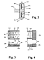
- FIG. 2 an embodiment of a vehicle lamp according to the invention is sketched in a sectional side view, in which a lens LS2 is designed as a perpendicular to the plane of FIG. 2 extending injection molding of transparent material.
- the profile contains, for example, an irradiated surface SF2, a contact shoulder AS2, rearwardly projecting wall webs RS and laterally protruding fastening projections BV.
- a circuit carrier ST here assumed as a single-layer circuit board, carries a plurality of light-emitting diodes of a light source LQ2 and optionally further components, not shown, in functional connection with the light source.
- sealing material DM applied to the hollow space HO2 between the circuit substrate and lens side of the circuit substrate preferably the entire surface between the wall webs RS of the lens.
- the hollow space HO2 is open perpendicular to the drawing plane of FIG. 2 a priori to both sides.
- a potting compound VM which may be the same material as the sealing material DM and which can also be applied together with this.
- the profile end by a remaining there only for the casting or permanently connected to the lamp body end wall plate be completed.
- a further delimitation in the form of an intermediate wall ZW can also be provided toward the cavity.
- the connecting cable KA2 as a multi-core cable is guided in the sketched example laterally away from the board and deflected backwards.
- the cable is enclosed during the introduction of the potting compound and / or the sealant of these and sealed.
- the cable can also be led out laterally by the potting compound VM and not deflected backwards.
- the cavity of a luminaire constructed according to FIG. 2 with a profile as a lens can be closed by an end cap VK, such an end cap VK sealingly sealing the cavity laterally with the profile and the circuit carrier ST.
- an end cap VK such an end cap VK sealingly sealing the cavity laterally with the profile and the circuit carrier ST.
- This can be done by gluing, by clamping elastic sealing elements on the end cap VK against surfaces of the lens and / or the circuit substrate or in turn by casting joints with sealing material.
- a feed line n form of a connection cable can also be guided in a sealed manner through the end closure cap to the outside.
- a recess NU is introduced on a surface of a rearwardly facing wall section RS of the lens LS, which may be formed, for example, as a longitudinal groove in a light disk profile.
- Sealing material DM penetrates when casting the cavity HO remote from the side of the circuit substrate ST in the recess NU as an extension and thus additionally causes the anchoring of the sealing material DM due to adhesion to the surface of the lens also as a positive anchoring.
- a wall opening DU is provided in the wall RS of the light disc LS delimiting the sealing material DM, which is filled with the sealing material.
- sealing material can also be applied outside the opening.
- a projection RN towards the sealing material is provided on the rearward-pointing wall section RS of the light disk LS, preferably on the rear edge of this wall section RS facing away from the hollow space HO, which protrudes toward the sealing material when the sealing material DM is introduced therefrom is flown behind, so that in turn a positive anchoring of the sealing material is formed.
- FIGS. 5 (A) and 5 (C) are particularly advantageous in the case of light disks in the form of extruded profiles, where the anchoring structures NU, RN can be produced without additional expenditure as part of the profile cross-section.
- the variant according to FIG. 5 (B) lends itself to molded-on light disks.
- the sealing material DM and / or the potting material VM can be applied, for example, as a thermoplastic material, in particular as a thermoplastic elastomer, in an injection molding process at elevated temperature and pressure, in which case support elements on the lens are advantageously provided on the lens to the circuit carrier, which reliably intercept the high pressure that occurs in such an injection molding process.
- support elements can, for example, as quasi point-like struts or be designed as partitions and are advantageously produced in the manufacture of the lens as an injection molded part without any special additional effort.
- sealing material DM and / or the potting material VM can be applied in castable, in particular low-viscosity form and solidify on the lamp body.
- the sealing material and the potting material are preferably after solidification permanently elastic materials.
Landscapes
- Engineering & Computer Science (AREA)
- Mechanical Engineering (AREA)
- Physics & Mathematics (AREA)
- Microelectronics & Electronic Packaging (AREA)
- Optics & Photonics (AREA)
- General Engineering & Computer Science (AREA)
- Arrangement Of Elements, Cooling, Sealing, Or The Like Of Lighting Devices (AREA)
- Non-Portable Lighting Devices Or Systems Thereof (AREA)
Applications Claiming Priority (1)
| Application Number | Priority Date | Filing Date | Title |
|---|---|---|---|
| DE102005001998A DE102005001998A1 (de) | 2005-01-15 | 2005-01-15 | Fahrzeugleuchte |
Publications (2)
| Publication Number | Publication Date |
|---|---|
| EP1681202A2 true EP1681202A2 (fr) | 2006-07-19 |
| EP1681202A3 EP1681202A3 (fr) | 2006-11-08 |
Family
ID=36121392
Family Applications (1)
| Application Number | Title | Priority Date | Filing Date |
|---|---|---|---|
| EP06000252A Withdrawn EP1681202A3 (fr) | 2005-01-15 | 2006-01-07 | Feu de véhicule |
Country Status (2)
| Country | Link |
|---|---|
| EP (1) | EP1681202A3 (fr) |
| DE (1) | DE102005001998A1 (fr) |
Cited By (3)
| Publication number | Priority date | Publication date | Assignee | Title |
|---|---|---|---|---|
| DE102008003270A1 (de) * | 2008-01-04 | 2009-07-09 | Schefenacker Grah Sg Automotive D.O.O. | Seitenleuchte für Kraftfahrzeuge |
| WO2013004608A1 (fr) * | 2011-07-01 | 2013-01-10 | Siteco Beleuchtungstechnik Gmbh | Système d'éclairage muni d'une matière d'étanchéité et de scellement |
| EP2857744A1 (fr) * | 2013-10-07 | 2015-04-08 | Hella KGaA Hueck & Co | Module à LED et système d'éclairage |
Families Citing this family (2)
| Publication number | Priority date | Publication date | Assignee | Title |
|---|---|---|---|---|
| DE102009016416B4 (de) * | 2009-04-04 | 2014-02-20 | Kesseböhmer Holding e.K. | Auszugsvorrichtung für Schrankauszüge |
| DE102010033297A1 (de) * | 2010-08-04 | 2012-02-09 | Hella Kgaa Hueck & Co. | Beleuchtungsvorrichtung und Dichtelement hierfür |
Citations (3)
| Publication number | Priority date | Publication date | Assignee | Title |
|---|---|---|---|---|
| US5038255A (en) * | 1989-09-09 | 1991-08-06 | Stanley Electric Co., Ltd. | Vehicle lamp |
| DE20011330U1 (de) * | 1999-07-08 | 2000-10-26 | Patent-Treuhand-Gesellschaft für elektrische Glühlampen mbH, 81543 München | Optoelektronische Bauteilgruppe |
| DE20304930U1 (de) | 2003-02-17 | 2003-08-07 | Aspöck Systems Ges.m.b.H., Peuerbach | Außenleuchte für Fahrzeuge |
Family Cites Families (6)
| Publication number | Priority date | Publication date | Assignee | Title |
|---|---|---|---|---|
| US5857767A (en) * | 1996-09-23 | 1999-01-12 | Relume Corporation | Thermal management system for L.E.D. arrays |
| US5896093A (en) * | 1998-04-03 | 1999-04-20 | Sjobom; Fritz C. | L.E.D. light assembly for traffic arrowboards |
| DE19922176C2 (de) * | 1999-05-12 | 2001-11-15 | Osram Opto Semiconductors Gmbh | Oberflächenmontierte LED-Mehrfachanordnung und deren Verwendung in einer Beleuchtungseinrichtung |
| GB2361989A (en) * | 2000-07-17 | 2001-11-07 | Designedge Europ Ltd | Luminaire which is edge-illuminated by an array of LEDs |
| US6871981B2 (en) * | 2001-09-13 | 2005-03-29 | Heads Up Technologies, Inc. | LED lighting device and system |
| DE102004036340A1 (de) * | 2004-07-27 | 2006-03-23 | Schmitz Gotha Fahrzeugwerke Gmbh | Heckleuchtenanordnung für Lastfahrzeuge, insbesondere Anhänger |
-
2005
- 2005-01-15 DE DE102005001998A patent/DE102005001998A1/de not_active Withdrawn
-
2006
- 2006-01-07 EP EP06000252A patent/EP1681202A3/fr not_active Withdrawn
Patent Citations (3)
| Publication number | Priority date | Publication date | Assignee | Title |
|---|---|---|---|---|
| US5038255A (en) * | 1989-09-09 | 1991-08-06 | Stanley Electric Co., Ltd. | Vehicle lamp |
| DE20011330U1 (de) * | 1999-07-08 | 2000-10-26 | Patent-Treuhand-Gesellschaft für elektrische Glühlampen mbH, 81543 München | Optoelektronische Bauteilgruppe |
| DE20304930U1 (de) | 2003-02-17 | 2003-08-07 | Aspöck Systems Ges.m.b.H., Peuerbach | Außenleuchte für Fahrzeuge |
Cited By (4)
| Publication number | Priority date | Publication date | Assignee | Title |
|---|---|---|---|---|
| DE102008003270A1 (de) * | 2008-01-04 | 2009-07-09 | Schefenacker Grah Sg Automotive D.O.O. | Seitenleuchte für Kraftfahrzeuge |
| WO2013004608A1 (fr) * | 2011-07-01 | 2013-01-10 | Siteco Beleuchtungstechnik Gmbh | Système d'éclairage muni d'une matière d'étanchéité et de scellement |
| CN103635744A (zh) * | 2011-07-01 | 2014-03-12 | 西特科照明有限公司 | 具有填料的发光装置 |
| EP2857744A1 (fr) * | 2013-10-07 | 2015-04-08 | Hella KGaA Hueck & Co | Module à LED et système d'éclairage |
Also Published As
| Publication number | Publication date |
|---|---|
| EP1681202A3 (fr) | 2006-11-08 |
| DE102005001998A1 (de) | 2006-07-20 |
Similar Documents
| Publication | Publication Date | Title |
|---|---|---|
| DE102008025398B4 (de) | Schutzumhüllung für ein LED-Band | |
| DE102011017162B4 (de) | Explosionsgeschütztes LED-Modul | |
| DE102009020851A1 (de) | Leuchtband und Verfahren zum Herstellen eines Leuchtbands | |
| DE4101418C2 (de) | Schalterbetätigte Warnleuchte zur Verwendung bei Fahrzeugen | |
| EP0818652A2 (fr) | Rampe d'éclairage et méthode de fabrication | |
| DE102007041817A1 (de) | Leuchtmodul und Verfahren zu dessen Herstellung | |
| EP2394093A2 (fr) | Module lumineux | |
| DE102006001947A1 (de) | Heckleuchtenanordnung | |
| EP2505906A2 (fr) | Procédé de fabrication d'une lampe à base de DEL | |
| EP1691131A1 (fr) | Lampe exterieure de vehicule et procédé de fabrication d'une telle lampe exterieure | |
| DE102008016697A1 (de) | Leuchte | |
| DE102005025214A1 (de) | Fahrzeugaußenleuchte und Verfahren zur Herstellung einer solchen Fahrzeugaußenleuchte | |
| DE202022106049U1 (de) | Anschlussverbindungselement für ein Leuchtdiodenband, mit einem Anschlussverbindungselement versehenes Leuchtdiodenband und Beleuchtungsstreifen mit einem solchen Leuchtdiodenband | |
| WO2016040972A1 (fr) | Appareil d'éclairage extérieur pour véhicule automobile | |
| EP2887778B1 (fr) | Carte de circuit souple avec dissipateur thermique et procédé pour sa fabrication | |
| DE102005001998A1 (de) | Fahrzeugleuchte | |
| EP3473066A1 (fr) | Feu de véhicules | |
| DE102015201152A1 (de) | Kühlkörper für eine Beleuchtungseinrichtung | |
| DE102008004799A1 (de) | Rundumleuchte, vorzugsweise Rundumkennleuchte | |
| DE102017101332A1 (de) | Vefahren zum Herstellen eines LED-Bandes | |
| EP4361496A1 (fr) | Elément de terminaison pour une bande de diodes électroluminescentes, bande de diodes électroluminescentes pourvue d'un élément de terminaison et bande d'éclairage dotée d'une telle bande de diodes électroluminescentes | |
| DE202008007474U1 (de) | Leuchtband mit einem biegeelastischen streifenförmigen Träger | |
| WO2024184450A1 (fr) | Dispositif d'éclairage comprenant une électronique intégrée | |
| DE102007010211B4 (de) | Leuchteinheit für Fahrzeuge und Montageverfahren | |
| DE102021127851A1 (de) | Wasserdichte LED-Anordnung |
Legal Events
| Date | Code | Title | Description |
|---|---|---|---|
| PUAI | Public reference made under article 153(3) epc to a published international application that has entered the european phase |
Free format text: ORIGINAL CODE: 0009012 |
|
| AK | Designated contracting states |
Kind code of ref document: A2 Designated state(s): AT BE BG CH CY CZ DE DK EE ES FI FR GB GR HU IE IS IT LI LT LU LV MC NL PL PT RO SE SI SK TR |
|
| AX | Request for extension of the european patent |
Extension state: AL BA HR MK YU |
|
| PUAL | Search report despatched |
Free format text: ORIGINAL CODE: 0009013 |
|
| RAP1 | Party data changed (applicant data changed or rights of an application transferred) |
Owner name: KOMPLED GMBH & CO. KG |
|
| AK | Designated contracting states |
Kind code of ref document: A3 Designated state(s): AT BE BG CH CY CZ DE DK EE ES FI FR GB GR HU IE IS IT LI LT LU LV MC NL PL PT RO SE SI SK TR |
|
| AX | Request for extension of the european patent |
Extension state: AL BA HR MK YU |
|
| 17P | Request for examination filed |
Effective date: 20061113 |
|
| 17Q | First examination report despatched |
Effective date: 20070111 |
|
| AKX | Designation fees paid | ||
| STAA | Information on the status of an ep patent application or granted ep patent |
Free format text: STATUS: THE APPLICATION IS DEEMED TO BE WITHDRAWN |
|
| 18D | Application deemed to be withdrawn |
Effective date: 20070522 |
|
| REG | Reference to a national code |
Ref country code: DE Ref legal event code: 8566 |