EP1681399A2 - Châssis de fenêtre adapté pour une fabrication standardisée - Google Patents
Châssis de fenêtre adapté pour une fabrication standardisée Download PDFInfo
- Publication number
- EP1681399A2 EP1681399A2 EP05388117A EP05388117A EP1681399A2 EP 1681399 A2 EP1681399 A2 EP 1681399A2 EP 05388117 A EP05388117 A EP 05388117A EP 05388117 A EP05388117 A EP 05388117A EP 1681399 A2 EP1681399 A2 EP 1681399A2
- Authority
- EP
- European Patent Office
- Prior art keywords
- sash
- frame
- window
- extra
- extra side
- Prior art date
- Legal status (The legal status is an assumption and is not a legal conclusion. Google has not performed a legal analysis and makes no representation as to the accuracy of the status listed.)
- Granted
Links
- 238000004519 manufacturing process Methods 0.000 title claims abstract description 14
- 238000007789 sealing Methods 0.000 claims abstract description 49
- 230000002787 reinforcement Effects 0.000 claims description 6
- 238000003780 insertion Methods 0.000 claims description 4
- 230000037431 insertion Effects 0.000 claims description 4
- 210000001503 joint Anatomy 0.000 claims description 3
- 238000009434 installation Methods 0.000 abstract description 8
- 230000000694 effects Effects 0.000 description 5
- 238000010586 diagram Methods 0.000 description 3
- 239000000463 material Substances 0.000 description 3
- 239000007769 metal material Substances 0.000 description 2
- 230000002349 favourable effect Effects 0.000 description 1
- 230000007774 longterm Effects 0.000 description 1
- 229910052755 nonmetal Inorganic materials 0.000 description 1
- 230000007704 transition Effects 0.000 description 1
- 239000002023 wood Substances 0.000 description 1
Images





Classifications
-
- E—FIXED CONSTRUCTIONS
- E04—BUILDING
- E04D—ROOF COVERINGS; SKY-LIGHTS; GUTTERS; ROOF-WORKING TOOLS
- E04D13/00—Special arrangements or devices in connection with roof coverings; Protection against birds; Roof drainage ; Sky-lights
- E04D13/03—Sky-lights; Domes; Ventilating sky-lights
- E04D13/035—Sky-lights; Domes; Ventilating sky-lights characterised by having movable parts
- E04D13/0351—Sky-lights; Domes; Ventilating sky-lights characterised by having movable parts the parts pivoting about a fixed axis
- E04D13/0354—Sky-lights; Domes; Ventilating sky-lights characterised by having movable parts the parts pivoting about a fixed axis the parts being flat
Definitions
- the present invention relates to a window sash, in particular to a window sash adapted for standardized manufacture, which constitutes a part of a window arranged in a building or a pitched roof.
- a window comprises a frame, a sash, a covering, a pane and other accessories.
- the frame comprises a top frame member, a bottom frame member and two side frame members; and the sash comprises a top sash member, a bottom sash member and two side sash members.
- a window arranged in a building or a pitched roof can meet requirements in use through a combination of said frame and sash with related accessories or parts and the combination of the frame with the sash. Furthermore, with a hinge device mounted in a central or top portion of a frame or a sash, the sash may pivot on an axis arranged in the central or top portion of the frame in an opened state, which are respectively referred to as a centre-hung window and a top-hung window hereinafter.
- window elements particularly the sash and frame
- Structures of the sash, frame and accessories thereof have a crucial effect on types of windows, processing, cost, installation, connection, sealing, waterproof, drain, usage and service, etc.
- an exposed sealing groove therefore is generally defined in a joining face of said frame and sash to obtain a sealing between these two parts, and a gasket is embedded in said sealing groove, then fixed. Therefore, although the gasket has been securely fastened by a fixing member, the exposed gasket is still prone to come off due to long term hit and press between the frame or sash and the gasket after the window has been used for a period of time, thereby the sealing between the frame and the sash become loose and the window cannot be normally used.
- parts of the frame and sash should be generally covered from outside by coverings so as to protect wood or other materials in the frame and sash from weathering such as rain, sunshine, wind and snow.
- the coverings for the frame and sash comprise a top covering, side coverings and a bottom covering.
- the sash and the coverings for the sash are mobile both when the sash is opened or closed. Particularly, at the instant that the sash is closed upon the frame, the sash and the coverings get trembled. Since the coverings are screwed directly onto the frame and sash and pressed thereon, and these coverings are generally made of thin metal material, the strength and stability of the sash coverings or the frame is not sufficient. The sash coverings are prone to distortion and slack after the window is used for a period of time.
- An object of the invention is to solve the above problem in the prior art and provide a window sash adapted for standardized manufacture.
- Another object of the invention is to provide a window sash with an excellent sealing between a window frame and the sash.
- Still another object of the invention is to provide a window sash with a covering of improved strength and little deformation.
- a window sash adapted for standardized manufacture comprises a basic sash frame and extra side plates fastened to outer surfaces of side sash members of the basic sash frame, said basic sash frame consisting of two side sash members, a top sash member and a bottom sash member which cooperatively form a closed sash frame, and said basic sash frame is a standard sash member, while said extra side plates are adapted for different types of windows.
- Said extra side plates may define a sealing groove in a longitudinal direction of the sash frame, and a gasket is received in said sealing groove to seal a gap between a window frame and the window sash.
- the top sash member of said basic sash frame extends upwardly from its rear side to form a rear plate of the top sash member so as to better fit different types of windows.
- Said extra side plate may be so arranged that their top surfaces locate above the top surface of the top sash member and approach a top edge of the rear plate for a top-hung window.
- Said extra side plates may be arranged on the outer surface of the side sash members with upper portions of these extra side plates close to middle regions of these sash members for a centre-hung window.
- a plurality of supports may be arranged on said extra side plates to support side coverings.
- Said supports may define a fixing hole therein for a corresponding side sash covering.
- the sash according to the invention comprises a basic sash frame and extra side plates fastened to side sash members thereof, such that the sash frame is adapted for standardized manufacture and suitable for different types of windows, especially for windows arranged in a building or a pitched roof.
- the extra side plates may be diversely configured for different types of windows. Therefore, a sash of this type may be economically, efficiently and effectively manufactured, while at the same time the installation, usage, service and management thereof is greatly facilitated.
- a support for a window covering is provided.
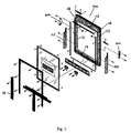
- Figs. 1 and 2 are schematic views showing installation diagrams of a basic sash frame 100 for a centre-hung window and a top-hung window, respectively.
- the basic sash frame 100 may be also used in other types of windows, such as a special window in which the hinge mechanism is arranged at a position between the top portion and central portion of the window.
- the window sash adapted for standardized manufacture comprises a basic sash frame 100 and extra side plates 211, 212 or 211', 212' fixed to the outer surface of side sash members 111, 112 of the sash frame 100.
- Said basic sash frame 100 consists of two side sash members 111, 112, a top sash member 113 and a bottom sash member 114, with all sash members coupled together to form a closed frame structure.
- the basic sash frame 100 is a standard member of a sash. Although two different types of windows are shown in Figs 1 and 2, respectively, the same basic sash frame 100 is adopted in both windows.
- the extra side plates 211, 212 in Fig. 1 and the extra side plates 211', 212' in Fig. 2 are non-standard parts and have different lengths and different top structures, suitable for different types of windows.
- Each of the extra side plates 211, 212 and 211' 212' defines a sealing groove 231 in a longitudinal direction of the basic sash frame 100, and a gasket 231 is received in the sealing groove 231 to seal a gap between a window frame and the window sash.
- top sash member 113 extends upwardly from its rear side to form a rear plate 115 of the top sash member so as to better fit different types of windows while reducing non-standard parts as much as possible and simplifying structures of these non-standard parts.
- the top element 213 can be of simple structure, i.e. nothing but a piece of top plate. The detailed structure of the top element 213 will be described hereinafter.
- the extra side plates 211', 212' are so arranged that their top surfaces are located above the top surface of the top sash member 113 and approach a top edge of the rear plate 115. Such a sash is hinged in a top region of a window frame.
- the extra side plates 211, 212 are arranged on the outer surface of the side sash members 111, 112 with upper portions of these extra side plates close to middle regions of these sash members. Materials may be saved with this design.
- Such a sash is hinged in a middle region of a window frame.
- each extra side plate 211, 212 defines a cutout corresponding to the outer profile of a hinge 400 at its upper end portion 232, so that an upper end portion 232 of the extra side plates 211, 212 may extend between the outer surfaces of the side sash members 111, 112 and the hinge 600, and this portion 232 is arranged neighboring a pivot axis of the hinge 400.
- the sealing between the exposed sash and the frame may be carried out by another gasket arranged in a corresponding position of the frame.
- the hinge 400 has an unfavorable effect on the sealing between the sash and the frame in this region.
- the gasket 300 in the sealing groove 231 can yield a wider sealing when the upper end portion 232 of the side plates 211, 212 is closer to the pivot axis of the hinge 400.
- sealing between the sash and frame in the hinge region is improved when the upper end portion 232 of the side plates 211, 212 is closer to the pivot axis of the hinge 400.
- the cutout defined in the upper end portion 232 of the side plate 211, 212 comprises an arc section and a straight section joined to the arc section with a smooth transition.
- the straight section forms a longitudinal protruding straight portion 233 at the upper end of the extra side plate 211, 212, and is inserted into a gap between the hinge 400 and the side sash member 111, 112, resulting in a satisfactory sealing between the sash and the frame in the hinge region.
- a ring sealing groove 118 is provided around the outer surface of the basic sash frame 100 so as to provide an overall sealing between the sash and the frame.
- a ring sealing flange 116 is formed along the periphery of the basic sash frame 100.
- the ring sealing groove 118 extends from the outer surface of the sash frame 100 toward the inside thereof, and the ring sealing flange 116 overlays the rear plate 115 of the top sash member.
- side walls of the ring sealing flange 116 are vertically arranged, and the straight flange 233 of upper end portion 232 of the extra side plates 211, 212 is received within the gap between the hinge 400 and a side wall of the ring sealing flange 116.
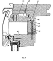
- a sealing groove 231 is provided (Fig. 4).
- the opening of the sealing groove 231 faces a side wall of the ring sealing flange 116, and a gasket 300 is received within the sealing groove 231. Therefore, the gasket 300 is sandwiched between the extra side plate and the side frame member, such that the deformation and breaking-off of the gasket 300 are prevented even though the sash is opened and closed many times.
- the sealing groove 231 in each extra side plate 211, 212, 211', 212' is a through groove, which extends from one end of the extra side plate to the other end thereof, so that an area covered by the sealing may be increased.
- the extra side plates 211, 212, 211', 212' each define a plurality of fixing holes on its outer surface.
- the extra side plate 211, 212, 211', 212' is fixed to the respective outer surface of the side frame member 111, 112 of the basic sash frame 100 by fasteners such as screws.
- Figs. 2 and 3 there are two symmetric extra side plates, i.e. plates 211, 212 and plates 211', 212', which are fixed to the left and right side frame members 111, 112 of the basic sash member 100, respectively.
- a top plate 213 is connected between top ends of the extra side plates 211', 212' to facilitate mounting of various components or accessories which are necessary for the top portion of the sash, for example, a hinge mechanism secured in the top portion of the sash.
- Top plate 213 is coupled to the rear plate 115 and two extra side plates 211', 212', respectively, through a lap joint or scarf joint, which improves the structural performance of the sash as a whole.
- a horizontal step 117 is provided at the upper front portion of the rear plate 115 of the top sash member so that it may be coupled to the top plate 213 through a lap joint
- another horizontal step 214 is correspondingly provided at the rear portion of the top plate 213 so that it may be coupled to the rear plate 115 through a lap joint.
- steps correspondingly coupled to said side plates 211', 212' may be provided on the top plate 213 at both sides so as to engage the inner straight surfaces of the extra side plates 211', 212' through a lap joint, respectively.
- the top plate 213 may be formed with two straight side faces, which can engage steps arranged on the inner surfaces of the extra side plates 211', 212' through a lap joint, respectively.
- the top plate 213 forms a favourable integral structure with the rear plate 115 and side plates 211', 212', respectively, through a lap joint or scarf joint, thereby forming an integral sash with the basic sash member 100 and other necessary accessories.
- the top plate 213, the rear plate 115 and the side plates 211', 212' may form an integral structure by other connecting means.
- two L-shaped hinge fixtures 410 are respectively fastened to two ends of the top plate 213 by screws.
- One leg of an L-shaped hinge fixture 410 is secured to the top surface of the top plate 213 by screw, and the other leg is secured to outer surface of the extra side plate 212', thereby the L-shaped hinge fixture 410 may connect the top plate 213 with the extra side plates 211', 212', and a hinge mechanism for sash rotation may be mounted thereon.
- the L-shaped hinge fixture 410 defines a plurality of fixing holes 411, 412 on its top surface and side surface, respectively, for the purpose of fixation.
- a connecting pivot shaft 413 coupled to the hinge mechanism is provided on the upper side surface of the L-shaped hinge fixture 410.
- a plurality of supports to support a side sash covering is arranged on both extra side plates to reinforce the side covering and prevent damage or deformation at edges of the side sash covering.
- the supports may also be provided on the bottom sash member to support the bottom sash covering, or be provided on the frame to support the frame covering, if necessary.
- the supports are not shown in Fig. 1.
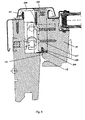
- Fig. 8 is a cross-sectional view showing left extra side plate 211', left side sash member 111 and correspondingly assembled frame, covering and pane.
- the side plate 211' is provided with a plurality of supports 600 to support the side sash covering 511.
- the support 600 may be made of non-metal materials and may be fixed to or embedded in the extra side plate 211'.
- the support 600 defines a fixing hole 611 for a corresponding side sash covering 511.
- a screw passes through the side sash covering 511 and fixes the covering to the support 600.
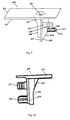
- Each support 600 comprises a first portion 610 and a second portion 620 which are integrally joined, so that the support 600 may perform better and may be arranged on the extra side plate 211' more conveniently (the extra side plate and the side member of the basic sash frame may be referred to as a side sash frame or a sash frame as a whole).
- a top surface of the first portion 610 is used as the supporting surface for the side covering 511, while the fixing hole 611 is opened from the top surface of the first portion 610 and extends into the second portion 620.
- the support 600 is provided with positioning pins 621, 622 such that the support 600 can be readily and firmly secured on the extra side plate 211'. It is understood that the support 600 may be attached by other means, such as a single positioning pin on the support, or a positioning block, or screws, etc. Respective positioning holes corresponding to these positioning pins 621, 622 are provided on the extra side plate 211'. Only one positioning pin 621 is schematically shown in Fig. 8, while the other positioning pin 622 is not shown.
- the positioning pins 621, 622 are arranged on an inner end surface 623 of the second portion 620.
- Said inner end surface 623 is a plane which snugly fits on an outer surface of the extra side plate such that the support 600 is more stable, and thus the support 600 may be firmly attached to the extra side plate while the supported side covering 511 may be steadily held, thereby the stability of the sash as a whole is improved.
- the positioning pins 621, 622 are perpendicularly arranged on inner end surface 623 of the second portion 620.
- the outer surface of the positioning pin 621 is provided with a plurality of umbrella-shaped frustum of a cone 624, with the frustum cone 624 tapering in an insertion direction of the positioning pin so that the positioning pin 621 may be readily secured in the positioning hole of the extra side plate 211' or side sash member.
- This facilitates an insertion of the positioning pin 620 while preventing the positioning pin 621 from moving outward and getting loosed.
- Such an effect is especially obvious when a screw exerts upon the fixing hole 611.
- the positioning pin has a substantially crisscross section.
- Each of the four flanges 625 of the crisscross forms a tapering section 626.
- Such a design is also advantageous for an insertion of the positioning pin 622 and further may prevent the positioning pin 622 from rotating in a circumference direction. This advantageous effect is also obvious when a screw exerts upon the fixing hole 611.
- the support 600 comprises two of said positioning pins 621, 622, which are respectively diagonally arranged on inner end surface 623 of the second portion 620, so as to effectively prevent the support 600 from rotating, improve stability of the side coverings 511 and increase the solidity of the integral structure of the sash.
- the support tends to move or sway upon vibration due to rotating of the sash and contact vibration between the sash and frame; furthermore, the support 600 tends to sway under non-even stress when the screws are forced into the support 600 since the support 600 is screw-fastened with the side covering 511.
- Arrangement of two positioning pins 621, 622, especially two diagonally disposed positioning pins 621, 622 can effectively prevent the support 600 from loosing, and may result in uniformly distributed stress on the support 600.
- the second portion 620 further defines a rod-shaped reinforcement portion 628 on the outer end surface 627 thereof to improve the structural strength of the support 600.
- the fixing hole 611 of the support 600 extends into said reinforcement portion 628.
- a triangular rib 629 is arranged between the outer end surface of the reinforcement portion 628 of the second portion 620 and the outer end surface 612 of the bottom surface of the first portion 610, so as to improve the structural strength of the support 600 as a whole.
- the support 600 may carry out various functions such as positioning, fixing and supporting, and the overall structure thereof is simple and compact.
- the inner end surface of the bottom surface of the first portion 610 has an inclined edge to facilitate connecting with the side sash covering and side sash member.
- An inclined surface is provided between the inner end surface of the bottom surface of the first portion 610 and the inner end surface of the second portion 620 to engage with the side sash member, so as to facilitate connection between the side sash covering and the side sash member.
Landscapes
- Engineering & Computer Science (AREA)
- Architecture (AREA)
- Civil Engineering (AREA)
- Structural Engineering (AREA)
- Hinges (AREA)
- Wing Frames And Configurations (AREA)
- Joining Of Corner Units Of Frames Or Wings (AREA)
- Transition And Organic Metals Composition Catalysts For Addition Polymerization (AREA)
- Cookers (AREA)
- Special Wing (AREA)
- Door And Window Frames Mounted To Openings (AREA)
Priority Applications (2)
| Application Number | Priority Date | Filing Date | Title |
|---|---|---|---|
| EP10165202A EP2221428A1 (fr) | 2004-12-24 | 2005-12-23 | Châssis de fenêtre adapté pour une fabrication standardisée |
| PL05388117T PL1681399T3 (pl) | 2004-12-24 | 2005-12-23 | Zestaw konstrukcyjny skrzydła okiennego przystosowanego do znormalizowanej produkcji |
Applications Claiming Priority (2)
| Application Number | Priority Date | Filing Date | Title |
|---|---|---|---|
| CN 200410102897 CN1796719B (zh) | 2004-12-24 | 2004-12-24 | 适合于标准化生产的窗扇 |
| CN 200420116269 CN2766007Y (zh) | 2004-12-24 | 2004-12-24 | 窗户罩板支撑座 |
Related Child Applications (1)
| Application Number | Title | Priority Date | Filing Date |
|---|---|---|---|
| EP10165202.2 Division-Into | 2010-06-08 |
Publications (3)
| Publication Number | Publication Date |
|---|---|
| EP1681399A2 true EP1681399A2 (fr) | 2006-07-19 |
| EP1681399A3 EP1681399A3 (fr) | 2009-02-11 |
| EP1681399B1 EP1681399B1 (fr) | 2010-07-14 |
Family
ID=36498932
Family Applications (2)
| Application Number | Title | Priority Date | Filing Date |
|---|---|---|---|
| EP10165202A Withdrawn EP2221428A1 (fr) | 2004-12-24 | 2005-12-23 | Châssis de fenêtre adapté pour une fabrication standardisée |
| EP05388117A Expired - Lifetime EP1681399B1 (fr) | 2004-12-24 | 2005-12-23 | Kit de construction de châssis de fenêtre adapté pour une fabrication standardisée |
Family Applications Before (1)
| Application Number | Title | Priority Date | Filing Date |
|---|---|---|---|
| EP10165202A Withdrawn EP2221428A1 (fr) | 2004-12-24 | 2005-12-23 | Châssis de fenêtre adapté pour une fabrication standardisée |
Country Status (4)
| Country | Link |
|---|---|
| EP (2) | EP2221428A1 (fr) |
| AT (1) | ATE474101T1 (fr) |
| DE (1) | DE602005022266D1 (fr) |
| PL (1) | PL1681399T3 (fr) |
Cited By (9)
| Publication number | Priority date | Publication date | Assignee | Title |
|---|---|---|---|---|
| US20120137607A1 (en) * | 2009-02-03 | 2012-06-07 | Lars Kristensen | Window having a sash and improved connection to the hinge |
| EP2554761A1 (fr) * | 2011-08-05 | 2013-02-06 | FAKRO PP Sp. z o.o. | Ensemble de couvercles latéraux du cadre d'une fenêtre de toiture |
| WO2013050045A1 (fr) * | 2011-10-04 | 2013-04-11 | Vkr Holding A/S | Fenêtre de toit munie de recouvrement de bourrelet d'impact amélioré |
| US20140366452A1 (en) * | 2011-10-04 | 2014-12-18 | Vkr Holding A/S | Roof window with a covering fastening device |
| US9016010B2 (en) | 2007-08-03 | 2015-04-28 | Vkr Holding A/S | Pane module for use in a window |
| US9115536B2 (en) | 2007-08-03 | 2015-08-25 | Vkr Holding A/S | Method for making a pane module and a window comprising such a pane module |
| US9453364B2 (en) | 2007-08-03 | 2016-09-27 | Vkr Holding A/S | Window comprising a bordered pane module |
| WO2018077367A1 (fr) * | 2016-10-31 | 2018-05-03 | Vkr Holding A/S | Procédé de fourniture d'un élément de couverture et élément de couverture pour couvrir une partie charnière d'une fenêtre de toit |
| US12459167B2 (en) | 2016-10-31 | 2025-11-04 | Vkr Holding A/S | Method for attaching two window components |
Families Citing this family (2)
| Publication number | Priority date | Publication date | Assignee | Title |
|---|---|---|---|---|
| DK180873B1 (en) * | 2018-11-06 | 2022-06-09 | Vkr Holding As | A roof window, and a method of assembling such a roof window |
| PL4466416T3 (pl) * | 2022-03-31 | 2025-09-08 | Vkr Holding A/S | Okno dachowe mające ościeżnicę z konstrukcjami odbiorczymi |
Citations (6)
| Publication number | Priority date | Publication date | Assignee | Title |
|---|---|---|---|---|
| US2552024A (en) | 1945-11-09 | 1951-05-08 | Hyde Park Lumber Company | Window construction |
| US2632927A (en) | 1947-03-21 | 1953-03-31 | Jarnland Sven Gustav Ejnar | Window |
| DE1273366B (de) | 1960-05-19 | 1968-07-18 | Evers & Co Aktiebolag | Lager fuer um eine mittlere waagerechte Achse schwingbare Fluegel von schraeg geneigten Fenstern |
| DE1784712A1 (de) | 1967-09-11 | 1971-08-12 | Rasmussen V B K | Anordnung an Oberlichtfenstern des Wendefluegeltyps |
| WO1998022683A1 (fr) | 1996-11-19 | 1998-05-28 | Velux Industri A/S | Fenetre presentant un risque limite de condensation |
| CN1304474A (zh) | 1998-04-07 | 2001-07-18 | 威卢克斯工业公司 | 带有主框架和窗框覆盖件的屋顶窗 |
Family Cites Families (4)
| Publication number | Priority date | Publication date | Assignee | Title |
|---|---|---|---|---|
| US4466221A (en) * | 1981-10-09 | 1984-08-21 | Wasco Products, Inc. | Thermal barrier skylight |
| DE8532011U1 (de) * | 1985-11-13 | 1986-01-02 | Paul Henke GmbH & Co KG, 4972 Löhne | Bodenträger |
| US5718493A (en) * | 1995-04-04 | 1998-02-17 | Nikolai; Gerhard | Cabinet construction system |
| FR2756714A1 (fr) * | 1996-12-05 | 1998-06-12 | Bruneau Bernard | Taquet d'armoire ou de meuble du meme genre |
-
2005
- 2005-12-23 DE DE602005022266T patent/DE602005022266D1/de not_active Expired - Lifetime
- 2005-12-23 PL PL05388117T patent/PL1681399T3/pl unknown
- 2005-12-23 AT AT05388117T patent/ATE474101T1/de not_active IP Right Cessation
- 2005-12-23 EP EP10165202A patent/EP2221428A1/fr not_active Withdrawn
- 2005-12-23 EP EP05388117A patent/EP1681399B1/fr not_active Expired - Lifetime
Patent Citations (6)
| Publication number | Priority date | Publication date | Assignee | Title |
|---|---|---|---|---|
| US2552024A (en) | 1945-11-09 | 1951-05-08 | Hyde Park Lumber Company | Window construction |
| US2632927A (en) | 1947-03-21 | 1953-03-31 | Jarnland Sven Gustav Ejnar | Window |
| DE1273366B (de) | 1960-05-19 | 1968-07-18 | Evers & Co Aktiebolag | Lager fuer um eine mittlere waagerechte Achse schwingbare Fluegel von schraeg geneigten Fenstern |
| DE1784712A1 (de) | 1967-09-11 | 1971-08-12 | Rasmussen V B K | Anordnung an Oberlichtfenstern des Wendefluegeltyps |
| WO1998022683A1 (fr) | 1996-11-19 | 1998-05-28 | Velux Industri A/S | Fenetre presentant un risque limite de condensation |
| CN1304474A (zh) | 1998-04-07 | 2001-07-18 | 威卢克斯工业公司 | 带有主框架和窗框覆盖件的屋顶窗 |
Cited By (15)
| Publication number | Priority date | Publication date | Assignee | Title |
|---|---|---|---|---|
| US9016009B2 (en) | 2007-08-03 | 2015-04-28 | Vkr Holding A/S | Pane module for use in a window |
| US9453364B2 (en) | 2007-08-03 | 2016-09-27 | Vkr Holding A/S | Window comprising a bordered pane module |
| US9376852B2 (en) | 2007-08-03 | 2016-06-28 | Vkr Holding A/S | Method for making a pane module and a window comprising such a pane module |
| US9115536B2 (en) | 2007-08-03 | 2015-08-25 | Vkr Holding A/S | Method for making a pane module and a window comprising such a pane module |
| US9016010B2 (en) | 2007-08-03 | 2015-04-28 | Vkr Holding A/S | Pane module for use in a window |
| US9051775B2 (en) * | 2009-02-03 | 2015-06-09 | Vkr Holding A/S | Window having a sash and improved connection to the hinge |
| US20120137607A1 (en) * | 2009-02-03 | 2012-06-07 | Lars Kristensen | Window having a sash and improved connection to the hinge |
| EP2554761A1 (fr) * | 2011-08-05 | 2013-02-06 | FAKRO PP Sp. z o.o. | Ensemble de couvercles latéraux du cadre d'une fenêtre de toiture |
| US20140366452A1 (en) * | 2011-10-04 | 2014-12-18 | Vkr Holding A/S | Roof window with a covering fastening device |
| WO2013050045A1 (fr) * | 2011-10-04 | 2013-04-11 | Vkr Holding A/S | Fenêtre de toit munie de recouvrement de bourrelet d'impact amélioré |
| US9469995B2 (en) * | 2011-10-04 | 2016-10-18 | Vkr Holding A/S | Roof window with a cover and a covering fastening device |
| WO2018077367A1 (fr) * | 2016-10-31 | 2018-05-03 | Vkr Holding A/S | Procédé de fourniture d'un élément de couverture et élément de couverture pour couvrir une partie charnière d'une fenêtre de toit |
| EP3733992A1 (fr) * | 2016-10-31 | 2020-11-04 | VKR Holding A/S | Set de fourniture d'un élément de couverture d'une partie de charnière d'une fenêtre de toit et utilisation dudit set |
| US11280092B2 (en) | 2016-10-31 | 2022-03-22 | Vkr Holding A/S | Method of providing a covering element and a covering element for covering a hinge part of a roof window |
| US12459167B2 (en) | 2016-10-31 | 2025-11-04 | Vkr Holding A/S | Method for attaching two window components |
Also Published As
| Publication number | Publication date |
|---|---|
| DE602005022266D1 (de) | 2010-08-26 |
| EP1681399A3 (fr) | 2009-02-11 |
| ATE474101T1 (de) | 2010-07-15 |
| EP2221428A1 (fr) | 2010-08-25 |
| EP1681399B1 (fr) | 2010-07-14 |
| PL1681399T3 (pl) | 2010-12-31 |
Similar Documents
| Publication | Publication Date | Title |
|---|---|---|
| KR101219555B1 (ko) | 태양전지 모듈 프레임 | |
| EP1681399B1 (fr) | Kit de construction de châssis de fenêtre adapté pour une fabrication standardisée | |
| KR101592152B1 (ko) | 구조보강과 간편하게 시공할 수 있는 발코니 개보수 창호와 그 시공 방법 | |
| JP4067570B2 (ja) | とくに傾斜屋根面に取り付けるための窓 | |
| CN107975320B (zh) | 一种装配式建筑门窗 | |
| US7181805B2 (en) | Sash window hinge | |
| CN108316810B (zh) | 门窗系统 | |
| CN221682785U (zh) | 组合式推拉门窗及其安装结构 | |
| CN209308295U (zh) | 天窗 | |
| JPH01153326A (ja) | 車両ルーフ | |
| JP7607440B2 (ja) | 障子および建具 | |
| CN115095063B (zh) | 一种幕墙 | |
| CN222909244U (zh) | 一种屋面顶棚耐力板幕墙开启天窗结构 | |
| JP7403694B2 (ja) | 改装建具及び改装建具の施工方法 | |
| JPH07229364A (ja) | 改装窓枠における雨仕舞構造 | |
| JP3141230B2 (ja) | ドアの水密構造 | |
| KR20010039839A (ko) | 무레일형 창호장치 | |
| JP2591639Y2 (ja) | 建具枠の補強構造 | |
| KR100538132B1 (ko) | 건축용 조립식 본문틀 구조 | |
| JPH07292825A (ja) | カーテンウォール用パネルユニット | |
| JP2024143901A (ja) | 建具 | |
| KR20260034186A (ko) | 샌드위치판넬 지붕재 연결부에 장착하는 누수방지커버 | |
| KR101063900B1 (ko) | 건축물 외벽용 유리노출타입 창호장치 | |
| CN211038297U (zh) | 一种窗框固定框及门窗 | |
| JP3542536B2 (ja) | 玄関サッシの密封装置 |
Legal Events
| Date | Code | Title | Description |
|---|---|---|---|
| PUAI | Public reference made under article 153(3) epc to a published international application that has entered the european phase |
Free format text: ORIGINAL CODE: 0009012 |
|
| AK | Designated contracting states |
Kind code of ref document: A2 Designated state(s): AT BE BG CH CY CZ DE DK EE ES FI FR GB GR HU IE IS IT LI LT LU LV MC NL PL PT RO SE SI SK TR |
|
| AX | Request for extension of the european patent |
Extension state: AL BA HR MK YU |
|
| RAP1 | Party data changed (applicant data changed or rights of an application transferred) |
Owner name: VKR HOLDING A/S |
|
| PUAL | Search report despatched |
Free format text: ORIGINAL CODE: 0009013 |
|
| AK | Designated contracting states |
Kind code of ref document: A3 Designated state(s): AT BE BG CH CY CZ DE DK EE ES FI FR GB GR HU IE IS IT LI LT LU LV MC NL PL PT RO SE SI SK TR |
|
| AX | Request for extension of the european patent |
Extension state: AL BA HR MK YU |
|
| 17P | Request for examination filed |
Effective date: 20090730 |
|
| AKX | Designation fees paid |
Designated state(s): AT BE BG CH CY CZ DE DK EE ES FI FR GB GR HU IE IS IT LI LT LU LV MC NL PL PT RO SE SI SK TR |
|
| GRAP | Despatch of communication of intention to grant a patent |
Free format text: ORIGINAL CODE: EPIDOSNIGR1 |
|
| RTI1 | Title (correction) |
Free format text: A WINDOW SASH CONSTRUCTION KIT ADAPTED FOR STANDARDIZED MANUFACTURE |
|
| GRAS | Grant fee paid |
Free format text: ORIGINAL CODE: EPIDOSNIGR3 |
|
| GRAA | (expected) grant |
Free format text: ORIGINAL CODE: 0009210 |
|
| AK | Designated contracting states |
Kind code of ref document: B1 Designated state(s): AT BE BG CH CY CZ DE DK EE ES FI FR GB GR HU IE IS IT LI LT LU LV MC NL PL PT RO SE SI SK TR |
|
| REG | Reference to a national code |
Ref country code: GB Ref legal event code: FG4D |
|
| REG | Reference to a national code |
Ref country code: CH Ref legal event code: EP |
|
| REG | Reference to a national code |
Ref country code: IE Ref legal event code: FG4D |
|
| REF | Corresponds to: |
Ref document number: 602005022266 Country of ref document: DE Date of ref document: 20100826 Kind code of ref document: P |
|
| REG | Reference to a national code |
Ref country code: NL Ref legal event code: VDEP Effective date: 20100714 |
|
| LTIE | Lt: invalidation of european patent or patent extension |
Effective date: 20100714 |
|
| REG | Reference to a national code |
Ref country code: PL Ref legal event code: T3 |
|
| PG25 | Lapsed in a contracting state [announced via postgrant information from national office to epo] |
Ref country code: LT Free format text: LAPSE BECAUSE OF FAILURE TO SUBMIT A TRANSLATION OF THE DESCRIPTION OR TO PAY THE FEE WITHIN THE PRESCRIBED TIME-LIMIT Effective date: 20100714 Ref country code: FI Free format text: LAPSE BECAUSE OF FAILURE TO SUBMIT A TRANSLATION OF THE DESCRIPTION OR TO PAY THE FEE WITHIN THE PRESCRIBED TIME-LIMIT Effective date: 20100714 Ref country code: AT Free format text: LAPSE BECAUSE OF FAILURE TO SUBMIT A TRANSLATION OF THE DESCRIPTION OR TO PAY THE FEE WITHIN THE PRESCRIBED TIME-LIMIT Effective date: 20100714 Ref country code: NL Free format text: LAPSE BECAUSE OF FAILURE TO SUBMIT A TRANSLATION OF THE DESCRIPTION OR TO PAY THE FEE WITHIN THE PRESCRIBED TIME-LIMIT Effective date: 20100714 |
|
| PG25 | Lapsed in a contracting state [announced via postgrant information from national office to epo] |
Ref country code: BG Free format text: LAPSE BECAUSE OF FAILURE TO SUBMIT A TRANSLATION OF THE DESCRIPTION OR TO PAY THE FEE WITHIN THE PRESCRIBED TIME-LIMIT Effective date: 20101014 Ref country code: SI Free format text: LAPSE BECAUSE OF FAILURE TO SUBMIT A TRANSLATION OF THE DESCRIPTION OR TO PAY THE FEE WITHIN THE PRESCRIBED TIME-LIMIT Effective date: 20100714 Ref country code: IS Free format text: LAPSE BECAUSE OF FAILURE TO SUBMIT A TRANSLATION OF THE DESCRIPTION OR TO PAY THE FEE WITHIN THE PRESCRIBED TIME-LIMIT Effective date: 20101114 Ref country code: CY Free format text: LAPSE BECAUSE OF FAILURE TO SUBMIT A TRANSLATION OF THE DESCRIPTION OR TO PAY THE FEE WITHIN THE PRESCRIBED TIME-LIMIT Effective date: 20100714 Ref country code: PT Free format text: LAPSE BECAUSE OF FAILURE TO SUBMIT A TRANSLATION OF THE DESCRIPTION OR TO PAY THE FEE WITHIN THE PRESCRIBED TIME-LIMIT Effective date: 20101115 |
|
| PG25 | Lapsed in a contracting state [announced via postgrant information from national office to epo] |
Ref country code: GR Free format text: LAPSE BECAUSE OF FAILURE TO SUBMIT A TRANSLATION OF THE DESCRIPTION OR TO PAY THE FEE WITHIN THE PRESCRIBED TIME-LIMIT Effective date: 20101015 Ref country code: LV Free format text: LAPSE BECAUSE OF FAILURE TO SUBMIT A TRANSLATION OF THE DESCRIPTION OR TO PAY THE FEE WITHIN THE PRESCRIBED TIME-LIMIT Effective date: 20100714 Ref country code: BE Free format text: LAPSE BECAUSE OF FAILURE TO SUBMIT A TRANSLATION OF THE DESCRIPTION OR TO PAY THE FEE WITHIN THE PRESCRIBED TIME-LIMIT Effective date: 20100714 Ref country code: SE Free format text: LAPSE BECAUSE OF FAILURE TO SUBMIT A TRANSLATION OF THE DESCRIPTION OR TO PAY THE FEE WITHIN THE PRESCRIBED TIME-LIMIT Effective date: 20100714 |
|
| PG25 | Lapsed in a contracting state [announced via postgrant information from national office to epo] |
Ref country code: DK Free format text: LAPSE BECAUSE OF FAILURE TO SUBMIT A TRANSLATION OF THE DESCRIPTION OR TO PAY THE FEE WITHIN THE PRESCRIBED TIME-LIMIT Effective date: 20100714 |
|
| PLBE | No opposition filed within time limit |
Free format text: ORIGINAL CODE: 0009261 |
|
| STAA | Information on the status of an ep patent application or granted ep patent |
Free format text: STATUS: NO OPPOSITION FILED WITHIN TIME LIMIT |
|
| PG25 | Lapsed in a contracting state [announced via postgrant information from national office to epo] |
Ref country code: IT Free format text: LAPSE BECAUSE OF FAILURE TO SUBMIT A TRANSLATION OF THE DESCRIPTION OR TO PAY THE FEE WITHIN THE PRESCRIBED TIME-LIMIT Effective date: 20100714 Ref country code: RO Free format text: LAPSE BECAUSE OF FAILURE TO SUBMIT A TRANSLATION OF THE DESCRIPTION OR TO PAY THE FEE WITHIN THE PRESCRIBED TIME-LIMIT Effective date: 20100714 Ref country code: SK Free format text: LAPSE BECAUSE OF FAILURE TO SUBMIT A TRANSLATION OF THE DESCRIPTION OR TO PAY THE FEE WITHIN THE PRESCRIBED TIME-LIMIT Effective date: 20100714 Ref country code: CZ Free format text: LAPSE BECAUSE OF FAILURE TO SUBMIT A TRANSLATION OF THE DESCRIPTION OR TO PAY THE FEE WITHIN THE PRESCRIBED TIME-LIMIT Effective date: 20100714 Ref country code: EE Free format text: LAPSE BECAUSE OF FAILURE TO SUBMIT A TRANSLATION OF THE DESCRIPTION OR TO PAY THE FEE WITHIN THE PRESCRIBED TIME-LIMIT Effective date: 20100714 |
|
| 26N | No opposition filed |
Effective date: 20110415 |
|
| PG25 | Lapsed in a contracting state [announced via postgrant information from national office to epo] |
Ref country code: ES Free format text: LAPSE BECAUSE OF FAILURE TO SUBMIT A TRANSLATION OF THE DESCRIPTION OR TO PAY THE FEE WITHIN THE PRESCRIBED TIME-LIMIT Effective date: 20101025 |
|
| REG | Reference to a national code |
Ref country code: DE Ref legal event code: R097 Ref document number: 602005022266 Country of ref document: DE Effective date: 20110415 |
|
| PG25 | Lapsed in a contracting state [announced via postgrant information from national office to epo] |
Ref country code: MC Free format text: LAPSE BECAUSE OF NON-PAYMENT OF DUE FEES Effective date: 20101231 |
|
| REG | Reference to a national code |
Ref country code: CH Ref legal event code: PL |
|
| GBPC | Gb: european patent ceased through non-payment of renewal fee |
Effective date: 20101223 |
|
| REG | Reference to a national code |
Ref country code: FR Ref legal event code: ST Effective date: 20110831 |
|
| PG25 | Lapsed in a contracting state [announced via postgrant information from national office to epo] |
Ref country code: FR Free format text: LAPSE BECAUSE OF NON-PAYMENT OF DUE FEES Effective date: 20110103 Ref country code: IE Free format text: LAPSE BECAUSE OF NON-PAYMENT OF DUE FEES Effective date: 20101223 Ref country code: LI Free format text: LAPSE BECAUSE OF NON-PAYMENT OF DUE FEES Effective date: 20101231 Ref country code: CH Free format text: LAPSE BECAUSE OF NON-PAYMENT OF DUE FEES Effective date: 20101231 |
|
| PG25 | Lapsed in a contracting state [announced via postgrant information from national office to epo] |
Ref country code: GB Free format text: LAPSE BECAUSE OF NON-PAYMENT OF DUE FEES Effective date: 20101223 |
|
| PG25 | Lapsed in a contracting state [announced via postgrant information from national office to epo] |
Ref country code: HU Free format text: LAPSE BECAUSE OF FAILURE TO SUBMIT A TRANSLATION OF THE DESCRIPTION OR TO PAY THE FEE WITHIN THE PRESCRIBED TIME-LIMIT Effective date: 20110115 Ref country code: LU Free format text: LAPSE BECAUSE OF NON-PAYMENT OF DUE FEES Effective date: 20101223 |
|
| PG25 | Lapsed in a contracting state [announced via postgrant information from national office to epo] |
Ref country code: TR Free format text: LAPSE BECAUSE OF FAILURE TO SUBMIT A TRANSLATION OF THE DESCRIPTION OR TO PAY THE FEE WITHIN THE PRESCRIBED TIME-LIMIT Effective date: 20100714 |
|
| PGFP | Annual fee paid to national office [announced via postgrant information from national office to epo] |
Ref country code: PL Payment date: 20201118 Year of fee payment: 16 |
|
| PGFP | Annual fee paid to national office [announced via postgrant information from national office to epo] |
Ref country code: DE Payment date: 20211102 Year of fee payment: 17 |
|
| REG | Reference to a national code |
Ref country code: DE Ref legal event code: R119 Ref document number: 602005022266 Country of ref document: DE |
|
| PG25 | Lapsed in a contracting state [announced via postgrant information from national office to epo] |
Ref country code: DE Free format text: LAPSE BECAUSE OF NON-PAYMENT OF DUE FEES Effective date: 20230701 |
|
| PG25 | Lapsed in a contracting state [announced via postgrant information from national office to epo] |
Ref country code: PL Free format text: LAPSE BECAUSE OF NON-PAYMENT OF DUE FEES Effective date: 20211223 |