EP1683614A1 - Papierschneidegerät - Google Patents
Papierschneidegerät Download PDFInfo
- Publication number
- EP1683614A1 EP1683614A1 EP20060250276 EP06250276A EP1683614A1 EP 1683614 A1 EP1683614 A1 EP 1683614A1 EP 20060250276 EP20060250276 EP 20060250276 EP 06250276 A EP06250276 A EP 06250276A EP 1683614 A1 EP1683614 A1 EP 1683614A1
- Authority
- EP
- European Patent Office
- Prior art keywords
- paper
- pressing plate
- cutting
- mounting base
- blade
- Prior art date
- Legal status (The legal status is an assumption and is not a legal conclusion. Google has not performed a legal analysis and makes no representation as to the accuracy of the status listed.)
- Withdrawn
Links
Images



Classifications
-
- B—PERFORMING OPERATIONS; TRANSPORTING
- B26—HAND CUTTING TOOLS; CUTTING; SEVERING
- B26D—CUTTING; DETAILS COMMON TO MACHINES FOR PERFORATING, PUNCHING, CUTTING-OUT, STAMPING-OUT OR SEVERING
- B26D7/00—Details of apparatus for cutting, cutting-out, stamping-out, punching, perforating, or severing by means other than cutting
- B26D7/01—Means for holding or positioning work
- B26D7/02—Means for holding or positioning work with clamping means
- B26D7/025—Means for holding or positioning work with clamping means acting upon planar surfaces
-
- B—PERFORMING OPERATIONS; TRANSPORTING
- B26—HAND CUTTING TOOLS; CUTTING; SEVERING
- B26D—CUTTING; DETAILS COMMON TO MACHINES FOR PERFORATING, PUNCHING, CUTTING-OUT, STAMPING-OUT OR SEVERING
- B26D7/00—Details of apparatus for cutting, cutting-out, stamping-out, punching, perforating, or severing by means other than cutting
- B26D7/01—Means for holding or positioning work
- B26D7/015—Means for holding or positioning work for sheet material or piles of sheets
-
- B—PERFORMING OPERATIONS; TRANSPORTING
- B26—HAND CUTTING TOOLS; CUTTING; SEVERING
- B26D—CUTTING; DETAILS COMMON TO MACHINES FOR PERFORATING, PUNCHING, CUTTING-OUT, STAMPING-OUT OR SEVERING
- B26D1/00—Cutting through work characterised by the nature or movement of the cutting member or particular materials not otherwise provided for; Apparatus or machines therefor; Cutting members therefor
- B26D1/01—Cutting through work characterised by the nature or movement of the cutting member or particular materials not otherwise provided for; Apparatus or machines therefor; Cutting members therefor involving a cutting member which does not travel with the work
- B26D1/12—Cutting through work characterised by the nature or movement of the cutting member or particular materials not otherwise provided for; Apparatus or machines therefor; Cutting members therefor involving a cutting member which does not travel with the work having a cutting member moving about an axis
- B26D1/14—Cutting through work characterised by the nature or movement of the cutting member or particular materials not otherwise provided for; Apparatus or machines therefor; Cutting members therefor involving a cutting member which does not travel with the work having a cutting member moving about an axis with a circular cutting member, e.g. disc cutter
- B26D1/157—Cutting through work characterised by the nature or movement of the cutting member or particular materials not otherwise provided for; Apparatus or machines therefor; Cutting members therefor involving a cutting member which does not travel with the work having a cutting member moving about an axis with a circular cutting member, e.g. disc cutter rotating about a movable axis
- B26D1/18—Cutting through work characterised by the nature or movement of the cutting member or particular materials not otherwise provided for; Apparatus or machines therefor; Cutting members therefor involving a cutting member which does not travel with the work having a cutting member moving about an axis with a circular cutting member, e.g. disc cutter rotating about a movable axis mounted on a movable carriage
- B26D1/185—Cutting through work characterised by the nature or movement of the cutting member or particular materials not otherwise provided for; Apparatus or machines therefor; Cutting members therefor involving a cutting member which does not travel with the work having a cutting member moving about an axis with a circular cutting member, e.g. disc cutter rotating about a movable axis mounted on a movable carriage for thin material, e.g. for sheets, strips or the like
-
- B—PERFORMING OPERATIONS; TRANSPORTING
- B26—HAND CUTTING TOOLS; CUTTING; SEVERING
- B26D—CUTTING; DETAILS COMMON TO MACHINES FOR PERFORATING, PUNCHING, CUTTING-OUT, STAMPING-OUT OR SEVERING
- B26D7/00—Details of apparatus for cutting, cutting-out, stamping-out, punching, perforating, or severing by means other than cutting
- B26D2007/0012—Details, accessories or auxiliary or special operations not otherwise provided for
- B26D2007/0087—Details, accessories or auxiliary or special operations not otherwise provided for for use on a desktop
-
- Y—GENERAL TAGGING OF NEW TECHNOLOGICAL DEVELOPMENTS; GENERAL TAGGING OF CROSS-SECTIONAL TECHNOLOGIES SPANNING OVER SEVERAL SECTIONS OF THE IPC; TECHNICAL SUBJECTS COVERED BY FORMER USPC CROSS-REFERENCE ART COLLECTIONS [XRACs] AND DIGESTS
- Y10—TECHNICAL SUBJECTS COVERED BY FORMER USPC
- Y10T—TECHNICAL SUBJECTS COVERED BY FORMER US CLASSIFICATION
- Y10T83/00—Cutting
- Y10T83/748—With work immobilizer
- Y10T83/7487—Means to clamp work
- Y10T83/7493—Combined with, peculiarly related to, other element
- Y10T83/7507—Guide for traveling cutter
-
- Y—GENERAL TAGGING OF NEW TECHNOLOGICAL DEVELOPMENTS; GENERAL TAGGING OF CROSS-SECTIONAL TECHNOLOGIES SPANNING OVER SEVERAL SECTIONS OF THE IPC; TECHNICAL SUBJECTS COVERED BY FORMER USPC CROSS-REFERENCE ART COLLECTIONS [XRACs] AND DIGESTS
- Y10—TECHNICAL SUBJECTS COVERED BY FORMER USPC
- Y10T—TECHNICAL SUBJECTS COVERED BY FORMER US CLASSIFICATION
- Y10T83/00—Cutting
- Y10T83/768—Rotatable disc tool pair or tool and carrier
- Y10T83/7755—Carrier for rotatable tool movable during cutting
- Y10T83/7763—Tool carrier reciprocable rectilinearly
-
- Y—GENERAL TAGGING OF NEW TECHNOLOGICAL DEVELOPMENTS; GENERAL TAGGING OF CROSS-SECTIONAL TECHNOLOGIES SPANNING OVER SEVERAL SECTIONS OF THE IPC; TECHNICAL SUBJECTS COVERED BY FORMER USPC CROSS-REFERENCE ART COLLECTIONS [XRACs] AND DIGESTS
- Y10—TECHNICAL SUBJECTS COVERED BY FORMER USPC
- Y10T—TECHNICAL SUBJECTS COVERED BY FORMER US CLASSIFICATION
- Y10T83/00—Cutting
- Y10T83/869—Means to drive or to guide tool
- Y10T83/8821—With simple rectilinear reciprocating motion only
- Y10T83/8822—Edge-to-edge of sheet or web [e.g., traveling cutter]
Definitions
- the present invention relates to a paper cutter for cutting a cutting object paper mounted on a paper mounting base by sliding a cutting blade along a guide rail.
- a paper cutter for cutting a cutting object paper mounted on a paper mounting base by sliding a cutting blade along a guide rail has been used.
- a paper pressing plate for nipping the cutting object paper together with the paper mounting base or the cutting blade just consists of transparent material, translucent material or opaque material.
- the present invention intends to provide a paper cutter capable of cutting a cutting object paper nipped by a paper pressing plate with a margin of a desired width from a cutting edge despite its simple structure.
- a paper cutter comprising: a paper pressing plate for nipping a cutting object mounted on a paper mounting base with a pressure; a slider on which a cutting blade is mounted; and a guide rail for guiding the slider slidably, wherein the paper pressing plate is formed of a transparent plate or a translucent plate and a scale comprising a plurality of lines parallel to a cutting line of the cutting blade is formed in the paper pressing plate.
- the scale parallel to the cutting edge is formed in the paper pressing plate formed of the transparent or translucent material, the width of a margin can be measured easily by seeing the scale. Additionally, a cutting position of the cutting object paper can be adjusted to have a desired margin width.
- the scale may be formed in a front face or a rear face of the paper pressing plate and for example, the scale may comprise a plurality of lines parallel to the cutting line by the cutting blade in a longitudinal direction of the paper pressing plate at an interval of several mm as a distance form the cutting line.
- the width of the margin can be adjusted by seeing the scale on the paper pressing plate through the same paper pressing plate. That is, by setting an edge of a photograph along the aforementioned scale line and measuring the length from that set position up to the fixed blade, the width of the margin may be adjusted.
- FIG. 1 shows an entire structure of a paper cutter according to one embodiment of the present invention.
- a guide rail is disposed on a rear face of a paper mounting base 2 and the guide rail is not disposed on the paper mounting base 2.
- a long fixed blade 5 whose front face is a substantially the same plane as a top face of the paper mounting base 2 while a guide rail 4 is mounted on a rear face of the fixed blade 5, is provided.
- a paper pressing plate 10 is disposed on a front face of the fixed blade 5.
- An elongated hole is formed in a longitudinal direction of the paper pressing plate at each of both end portions of the paper pressing plate 10, and a collar member 26 is loosely fitted to the elongated hole such that it is capable of moving.
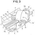
- the paper pressing plate 10 is attached to the paper mounting base 2 via a screw 26a (see FIG. 3) inserted into each collar member 26.
- a gap can be formed between the paper pressing plate 10 and the paper mounting base 2 by pulling up the paper pressing plate 10 in a direction of departing from the paper mounting base 2.
- the edge on an opposite side to the fixed blade 5 of the paper pressing plate 10 is formed into an inclined face having an opened insertion mouth so as to guide the cutting object paper mounted on the paper mounting base 2 for easy insertion of the paper.
- the paper pressing plate 10 comprises a transparent plate and a scale 10a parallel to the cutting line of the fixed blade 5, i.e. , a cutting edge of the fixed blade is formed on a front face side or a rear face side of the paper pressing plate 10.
- the width of a margin can be adjusted using the line of the scale 10a through the transparent paper pressing plate 10.
- the paper pressing plate 10 may comprise not only the transparent plate but also a translucent plate or the like as long as an end or the like of a cutting object paper can be recognized visually through the paper pressing plate 10.
- supporting members 13a, 13b are disposed on both ends of the paper pressing base 2, and the supporting members constitute a stopper for a paper pressing plate pressing portion 15 or the like sliding along the guide rail 4.
- the end face of each of the supporting members 13a, 13b is covered with a cover 14.
- a guide piece 3 for restricting the position of one side of the cutting object paper is fixed to one side edge side of the paper mounting base 2 with screws 24.
- the fixed blade 5 has a L-shaped section and is fixed to the paper mounting base 2 with screws or the like (not shown) with its L-shaped top face substantially flush with the top face of the paper mounting base 2.
- the substantially U-shaped guide rail 4 which extends parallel to the cutting line of the fixed blade, is fixed by screws or the like (not shown).
- a dust tray 25 is attached to an end portion of the paper mounting base 2 below the fixed blade 5.
- a supporting shaft (not shown) is formed at an end portion of each of the supporting members 13a, 13b disposed on both ends of the paper mounting base 2 and the same supporting shaft acts as a supporting shaft for rotation at an end of an auxiliary paper mounting base 22 disposed on the rear face side of the paper mounting base 2 such that it is capable of being accommodated freely.
- a mobile member 8 is disposed slidably in a groove of the guide rail 4 and a rotary blade holder 7 and an arm 9 are mounted on this mobile member 8 with screw or the like (not shown). That is, the arm 9 is connected to the mobile member 8 disposed on the rear face side of the fixed blade 5 striding over the fixed blade 5, and independently of the arm 9, the rotary blade holder 7 is connected to the mobile member 8 disposed on the rear face side of the fixed blade 5 striding over the fixed blade 5.
- the rotary blade holder 7 is accommodated within a pair of upper and lower covers 15a attached to the arm 9.
- a rotary circular blade 6 is supported rotatably by a shaft 6a within the rotary blade holder 7.
- the shaft 6a of the rotary circular blade 6 is disposed above the top face of the fixed blade 5.
- the arm 9 is provided with a paper pressing plate pressing portion 15 for pressing the paper pressing plate 10.
- the paper pressing plate pressing portion 15 is disposed within a pair of upper and lower covers 15a in FIGS. 1 and 2.
- the paper pressing plate pressing portion 15 includes a pressing roller 16, a roller holder 16a supporting the pressing roller 16 rotatably, a leaf spring or the like (not shown) for urging the roller holder 16a toward a side of the paper pressing plate 10.
- the roller holder 16a is attached to the arm 9 via the leaf spring.
- a slider comprises the rotary blade holder 7 sliding together with the mobilebody8, thearm9, the paper pressing plate pressing portion 15 and the pair of the upper and lower covers 15a.
- a pressing position of the paper pressing plate 10 by the pressing roller 16 is set forward in a cutting direction of the rotary circular blade 6 with respect to a cutting position by the rotary blade 6 and the fixed blade 5.
- cutting of the cutting object paper can be carried out by the rotary blade 6 and the fixed blade 5 with the paper pressing plate 10 pressed forward of the cutting position so as to prevent , the cutting object paper from deflecting upon the cutting.
- a grip 12 is formed on the pair of upper and lower covers 15a. Further, a rubber portion 12a is disposed on a peripheral portion of the grip 12 to improve a contact condition with the hand, which presses and operates the grip 12.
- the pair of upper and lower covers 15a may be slid along the guide rail 4. Consequently, the cutting object paper nipped between the fixed blade 5 and the paper pressing plate 10 can be cut by the rotary circular blade 6 and the fixed blade 5. Further, a cut piece may be stored within the dust tray 25.
- a scale 10a comprising a plurality of lines and indicating a distance from the cutting line is formed on the rear face side of the paper pressing plate 10.
- the width of a margin to be formed around the photograph can be adjusted arbitrarily. That is, by cutting the photographic paper, on which the photograph is printed, at a position apart from the cutting line of the fixed blade 5 by a predetermined distance, the width of the margin around the photograph can be formed corresponding to the predetermined distance from the cutting line of the fixed blade 5.
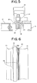
- FIG. 4 shows an entire perspective view of the paper cutter 1 of the invention and FIG. 5 shows a sectional view taken along the line V-V of FIG. 4.
- FIG. 6 shows a partially plan view of the structure of a paper pressing plate 36.
- a guide rail 32 for sliding and guiding a slider 33 is disposed at a side of an end of a paper mounting base 31. Both ends of the guide rail 32 are provided such that they can be raised or lowered by supporting members 34, 35 fixed on the paper mounting base 31.
- the paper pressing plate 36 located below the guide rail 32 is provided such that it can independently be raised or lowered vertically with respect to the paper mounting base 31.
- a slider 33 is mounted slidably on the guide rail 32.
- the slider 33 is disposed such that it is slidably fitted to the guide rail 32 and a side face of a rotary circular blade 37 supported rotatably by the slider 33 is kept in contact with a side edge of the paper pressing plate 36.
- the side edge of the paper pressing plate 36 serves as the cutting line by the rotary circular blade 37.
- the paper mounting base 31 which the blade of the rotary circular blade 37 comes into contact with is provided with rubber 38 for protecting the tip of the rotary circular blade 37.
- the paper pressing plate 36 comprises a transparent long plate and a scale 36a is formed of lines drawn in parallel from the cutting line at an interval of several mm in a rear face side of the paper pressing plate 36.
- the paper pressing plate 36 may comprise a translucent material or the scale 36a may be formed in a front face of the paper pressing plate 36 as long as a portion constituting a margin of the paper can be seen through the paper pressing plate 36.
- the guide rail 32 By pressing the slider 33, as shown in FIGS. 4 and 5, the guide rail 32 may be lowered in parallel to the paper mounting base 31 with guided by the supporting members 34, 35. And at the same time, by lowering the paper pressing plate 36, the cutting object paper can be nipped between the paper pressing plate 36 and the paper mounting base 31.
- the width of the margin to be formed on the cutting object paper can be adjusted with watching the scale 36a.
- the guide rail 32 is moved upward by a drive mechanism (not shown).
- the paper pressing plate 36 is raised vertically with respect to the paper mounting base 31 by a compression spring 39 while guided by a guide member (not shown) until its stopper member (not shown) comes into contact with the guide rail 32.
- the top face of the paper mounting base 31 and the paper pressing plate 36 are parallelized each other so that a gap is formed therebetween.
- the scale 10a, 36a is formed in the paper pressing plate at an interval of several mm
- the scale may be formed of lines at an interval of 1 mm or at an interval of other unit, for example, inch.
- the plate of the invention is not limited to a plate for pressing a paper.
- the technology of the invention can be applied to an apparatus having the same configuration as the paper cutter.
Landscapes
- Life Sciences & Earth Sciences (AREA)
- Forests & Forestry (AREA)
- Engineering & Computer Science (AREA)
- Mechanical Engineering (AREA)
- Nonmetal Cutting Devices (AREA)
- Details Of Cutting Devices (AREA)
Applications Claiming Priority (1)
| Application Number | Priority Date | Filing Date | Title |
|---|---|---|---|
| JP2005011916A JP2006198711A (ja) | 2005-01-19 | 2005-01-19 | 紙裁断機 |
Publications (1)
| Publication Number | Publication Date |
|---|---|
| EP1683614A1 true EP1683614A1 (de) | 2006-07-26 |
Family
ID=36097208
Family Applications (1)
| Application Number | Title | Priority Date | Filing Date |
|---|---|---|---|
| EP20060250276 Withdrawn EP1683614A1 (de) | 2005-01-19 | 2006-01-19 | Papierschneidegerät |
Country Status (3)
| Country | Link |
|---|---|
| US (1) | US20060156886A1 (de) |
| EP (1) | EP1683614A1 (de) |
| JP (1) | JP2006198711A (de) |
Cited By (1)
| Publication number | Priority date | Publication date | Assignee | Title |
|---|---|---|---|---|
| CN103640037A (zh) * | 2013-11-22 | 2014-03-19 | 无锡睿网科技有限公司 | 一种裁纸刀 |
Families Citing this family (14)
| Publication number | Priority date | Publication date | Assignee | Title |
|---|---|---|---|---|
| WO2009104456A1 (ja) * | 2008-02-22 | 2009-08-27 | カール事務器株式会社 | 裁断機 |
| CN104128951A (zh) * | 2013-05-03 | 2014-11-05 | 昆山泰士特信息技术有限公司 | 一种新型的切纸刀 |
| US9919834B2 (en) * | 2014-01-09 | 2018-03-20 | Oria Collapsibles, Llc | Pallet construction line and assembly |
| USD914800S1 (en) * | 2019-01-24 | 2021-03-30 | Erwin Müller GmbH | Machine for cutting paper |
| USD917612S1 (en) * | 2019-01-24 | 2021-04-27 | Erwin Müller GmbH | Machine for cutting paper |
| CN109940668A (zh) * | 2019-04-18 | 2019-06-28 | 吴时希 | 滚轮式裁纸器 |
| CN112571499B (zh) * | 2020-11-24 | 2022-05-03 | 深圳市成豪建设集团有限公司 | 一种建筑幕墙用铝塑板裁剪加工方法 |
| CN112571498B (zh) * | 2020-11-24 | 2022-12-20 | 温州开玩贸易有限公司 | 一种铝塑板加工系统 |
| CN113276187B (zh) * | 2021-04-26 | 2022-06-03 | 武汉华夏理工学院 | 一种药品包装用铝箔切割设备 |
| CN114260958A (zh) * | 2021-12-28 | 2022-04-01 | 马鞍山市康辉纸箱纸品有限公司 | 一种用于纸箱生产的切边装置 |
| USD1055659S1 (en) * | 2022-02-17 | 2024-12-31 | Tonic Studios Limited | Trimmer |
| USD1055658S1 (en) * | 2022-02-17 | 2024-12-31 | Tonic Studios Limited | Trimmer |
| CN118061261A (zh) * | 2022-11-11 | 2024-05-24 | 南通华兴办公设备科技有限公司 | 裁纸机 |
| JP1769525S (ja) * | 2023-09-04 | 2024-05-01 | カッティングプロッタ用静電吸着具 |
Citations (13)
| Publication number | Priority date | Publication date | Assignee | Title |
|---|---|---|---|---|
| DE744752C (de) * | 1940-11-17 | 1944-01-24 | Hugo Tollert | Beschneidevorrichtung fuer Papier o. dgl. |
| CH317989A (de) * | 1956-02-11 | 1956-12-15 | Gilich Rudolf | Vorrichtung zum Schneiden von Gegenständen aus Papier, Karton, Leder und dergleichen |
| GB1141951A (en) * | 1967-01-18 | 1969-02-05 | Doherty Sons Ltd Edward | Device for trimming paper and like sheet material |
| GB1210919A (en) * | 1967-11-20 | 1970-11-04 | Rotaspray Products Ltd | Paper trimmer |
| US4056027A (en) * | 1976-06-07 | 1977-11-01 | Northrop Tom A | Cutting device |
| GB2016349A (en) * | 1978-03-16 | 1979-09-26 | Myers Sons Ltd M | Apparatus for cutting board, card or paper material |
| DE3134577A1 (de) * | 1981-09-01 | 1983-03-10 | Meteor-Siegen Apparatebau Paul Schmeck Gmbh, 5900 Siegen | Elektrische schneidmaschine |
| GB2141371A (en) * | 1983-06-13 | 1984-12-19 | Rotatrim Ltd | Apparatus for cutting sheet material |
| US5347724A (en) * | 1993-08-02 | 1994-09-20 | Hankins Daniel C | Cropping template |
| US5819618A (en) * | 1994-05-10 | 1998-10-13 | Martin Yale Industries, Inc. | Rotary paper trimmer |
| WO1999058305A1 (en) * | 1998-05-12 | 1999-11-18 | Hunt Holdings, Inc. | Compact trimmer |
| DE20319003U1 (de) * | 2003-05-08 | 2004-03-04 | Swedex Gmbh & Co. Kg | Schneidgerät |
| EP1493540A2 (de) * | 2003-07-03 | 2005-01-05 | Hermann Schwelling | Papierschneidgerät |
Family Cites Families (6)
| Publication number | Priority date | Publication date | Assignee | Title |
|---|---|---|---|---|
| JP3832799B2 (ja) * | 1999-12-08 | 2006-10-11 | 富士写真フイルム株式会社 | シート切断装置及びカッタ付きプリンタ |
| US20030140757A1 (en) * | 2002-01-25 | 2003-07-31 | Alterra Holdings Corporation | Storage compartment for a paper trimmer |
| TW200420397A (en) * | 2003-01-24 | 2004-10-16 | Fiskars Brands Inc | Craft trimmer assembly |
| US20040221703A1 (en) * | 2003-05-08 | 2004-11-11 | Bernd Loibl | Cutting unit |
| TWI222400B (en) * | 2003-05-13 | 2004-10-21 | Primax Electronics Ltd | Pressing device and cutting apparatus using the pressing device |
| JP4646598B2 (ja) * | 2004-11-02 | 2011-03-09 | カール事務器株式会社 | 紙裁断機 |
-
2005
- 2005-01-19 JP JP2005011916A patent/JP2006198711A/ja active Pending
-
2006
- 2006-01-18 US US11/334,194 patent/US20060156886A1/en not_active Abandoned
- 2006-01-19 EP EP20060250276 patent/EP1683614A1/de not_active Withdrawn
Patent Citations (13)
| Publication number | Priority date | Publication date | Assignee | Title |
|---|---|---|---|---|
| DE744752C (de) * | 1940-11-17 | 1944-01-24 | Hugo Tollert | Beschneidevorrichtung fuer Papier o. dgl. |
| CH317989A (de) * | 1956-02-11 | 1956-12-15 | Gilich Rudolf | Vorrichtung zum Schneiden von Gegenständen aus Papier, Karton, Leder und dergleichen |
| GB1141951A (en) * | 1967-01-18 | 1969-02-05 | Doherty Sons Ltd Edward | Device for trimming paper and like sheet material |
| GB1210919A (en) * | 1967-11-20 | 1970-11-04 | Rotaspray Products Ltd | Paper trimmer |
| US4056027A (en) * | 1976-06-07 | 1977-11-01 | Northrop Tom A | Cutting device |
| GB2016349A (en) * | 1978-03-16 | 1979-09-26 | Myers Sons Ltd M | Apparatus for cutting board, card or paper material |
| DE3134577A1 (de) * | 1981-09-01 | 1983-03-10 | Meteor-Siegen Apparatebau Paul Schmeck Gmbh, 5900 Siegen | Elektrische schneidmaschine |
| GB2141371A (en) * | 1983-06-13 | 1984-12-19 | Rotatrim Ltd | Apparatus for cutting sheet material |
| US5347724A (en) * | 1993-08-02 | 1994-09-20 | Hankins Daniel C | Cropping template |
| US5819618A (en) * | 1994-05-10 | 1998-10-13 | Martin Yale Industries, Inc. | Rotary paper trimmer |
| WO1999058305A1 (en) * | 1998-05-12 | 1999-11-18 | Hunt Holdings, Inc. | Compact trimmer |
| DE20319003U1 (de) * | 2003-05-08 | 2004-03-04 | Swedex Gmbh & Co. Kg | Schneidgerät |
| EP1493540A2 (de) * | 2003-07-03 | 2005-01-05 | Hermann Schwelling | Papierschneidgerät |
Cited By (1)
| Publication number | Priority date | Publication date | Assignee | Title |
|---|---|---|---|---|
| CN103640037A (zh) * | 2013-11-22 | 2014-03-19 | 无锡睿网科技有限公司 | 一种裁纸刀 |
Also Published As
| Publication number | Publication date |
|---|---|
| US20060156886A1 (en) | 2006-07-20 |
| JP2006198711A (ja) | 2006-08-03 |
Similar Documents
| Publication | Publication Date | Title |
|---|---|---|
| EP1683614A1 (de) | Papierschneidegerät | |
| JP4947904B2 (ja) | 紙裁断機 | |
| EP1900535A3 (de) | Banddruckvorrichtung | |
| IT9021622A1 (it) | Avvitatore per viti collegate da una striscia | |
| ATE456433T1 (de) | Vorrichtung zum schneiden von papier | |
| US20120111169A1 (en) | Sheet Cutting Apparatus | |
| JP2006198739A5 (de) | ||
| ATE13269T1 (de) | Schneideeinrichtung fuer einen seriellen drucker. | |
| US20100244372A1 (en) | Sheet separation device, sheet feed tray including the sheet separation device, and sheet feed apparatus including the sheet separation device | |
| EP1642738A3 (de) | Bildaufzeichnungsmaterialführungsvorrichtung und Aufzeichnungsgerät | |
| US20050120850A1 (en) | Cutting unit | |
| KR102575811B1 (ko) | 권취형 필름 절단장치 | |
| JPH0530200B2 (de) | ||
| US4698883A (en) | Cutting and mounting apparatus | |
| JP3729688B2 (ja) | エレベータ上下終点スイッチ間隙測定装置 | |
| US20090151528A1 (en) | Office accessory for processing sheet material | |
| CN215881758U (zh) | 一种财会用自动压剪纸装置 | |
| CN213350621U (zh) | 一种ffc生产用冲切装置 | |
| JPH0929687A (ja) | シート切断装置 | |
| JPH11334162A (ja) | カッティング機能付き装置におけるカッター昇降機構 | |
| JP3194893B2 (ja) | スライドガラス保持具 | |
| JPH0229074Y2 (de) | ||
| JP3516396B2 (ja) | 障子紙切断器 | |
| JPH0123136Y2 (de) | ||
| KR101266892B1 (ko) | 다용도 기능을 갖는 자 |
Legal Events
| Date | Code | Title | Description |
|---|---|---|---|
| PUAI | Public reference made under article 153(3) epc to a published international application that has entered the european phase |
Free format text: ORIGINAL CODE: 0009012 |
|
| 17P | Request for examination filed |
Effective date: 20060206 |
|
| AK | Designated contracting states |
Kind code of ref document: A1 Designated state(s): AT BE BG CH CY CZ DE DK EE ES FI FR GB GR HU IE IS IT LI LT LU LV MC NL PL PT RO SE SI SK TR |
|
| AX | Request for extension of the european patent |
Extension state: AL BA HR MK YU |
|
| STAA | Information on the status of an ep patent application or granted ep patent |
Free format text: STATUS: THE APPLICATION HAS BEEN WITHDRAWN |
|
| 18W | Application withdrawn |
Effective date: 20061114 |