EP1683703A1 - Arbre de direction avec un dispositif d'accouplement elastique - Google Patents
Arbre de direction avec un dispositif d'accouplement elastique Download PDFInfo
- Publication number
- EP1683703A1 EP1683703A1 EP06001216A EP06001216A EP1683703A1 EP 1683703 A1 EP1683703 A1 EP 1683703A1 EP 06001216 A EP06001216 A EP 06001216A EP 06001216 A EP06001216 A EP 06001216A EP 1683703 A1 EP1683703 A1 EP 1683703A1
- Authority
- EP
- European Patent Office
- Prior art keywords
- shaft
- steering
- extension shaft
- steering apparatus
- constant velocity
- Prior art date
- Legal status (The legal status is an assumption and is not a legal conclusion. Google has not performed a legal analysis and makes no representation as to the accuracy of the status listed.)
- Withdrawn
Links
- 230000008878 coupling Effects 0.000 title claims abstract description 63
- 238000010168 coupling process Methods 0.000 title claims abstract description 63
- 238000005859 coupling reaction Methods 0.000 title claims abstract description 63
- 230000005540 biological transmission Effects 0.000 claims description 4
- 230000002093 peripheral effect Effects 0.000 description 13
- 238000005452 bending Methods 0.000 description 9
- 239000004033 plastic Substances 0.000 description 7
- 241000239290 Araneae Species 0.000 description 6
- 239000013536 elastomeric material Substances 0.000 description 2
- 230000007935 neutral effect Effects 0.000 description 2
- 239000000853 adhesive Substances 0.000 description 1
- 230000001070 adhesive effect Effects 0.000 description 1
- 230000000295 complement effect Effects 0.000 description 1
- 230000003247 decreasing effect Effects 0.000 description 1
- 238000010438 heat treatment Methods 0.000 description 1
Images


Classifications
-
- F—MECHANICAL ENGINEERING; LIGHTING; HEATING; WEAPONS; BLASTING
- F16—ENGINEERING ELEMENTS AND UNITS; GENERAL MEASURES FOR PRODUCING AND MAINTAINING EFFECTIVE FUNCTIONING OF MACHINES OR INSTALLATIONS; THERMAL INSULATION IN GENERAL
- F16D—COUPLINGS FOR TRANSMITTING ROTATION; CLUTCHES; BRAKES
- F16D3/00—Yielding couplings, i.e. with means permitting movement between the connected parts during the drive
- F16D3/16—Universal joints in which flexibility is produced by means of pivots or sliding or rolling connecting parts
- F16D3/26—Hooke's joints or other joints with an equivalent intermediate member to which each coupling part is pivotally or slidably connected
- F16D3/30—Hooke's joints or other joints with an equivalent intermediate member to which each coupling part is pivotally or slidably connected in which the coupling is specially adapted to constant velocity-ratio
- F16D3/32—Hooke's joints or other joints with an equivalent intermediate member to which each coupling part is pivotally or slidably connected in which the coupling is specially adapted to constant velocity-ratio by the provision of two intermediate members each having two relatively perpendicular trunnions or bearings
-
- B—PERFORMING OPERATIONS; TRANSPORTING
- B62—LAND VEHICLES FOR TRAVELLING OTHERWISE THAN ON RAILS
- B62D—MOTOR VEHICLES; TRAILERS
- B62D1/00—Steering controls, i.e. means for initiating a change of direction of the vehicle
- B62D1/02—Steering controls, i.e. means for initiating a change of direction of the vehicle vehicle-mounted
- B62D1/16—Steering columns
- B62D1/20—Connecting steering column to steering gear
-
- B—PERFORMING OPERATIONS; TRANSPORTING
- B62—LAND VEHICLES FOR TRAVELLING OTHERWISE THAN ON RAILS
- B62D—MOTOR VEHICLES; TRAILERS
- B62D7/00—Steering linkage; Stub axles or their mountings
- B62D7/22—Arrangements for reducing or eliminating reaction, e.g. vibration, from parts, e.g. wheels, of the steering system
- B62D7/224—Arrangements for reducing or eliminating reaction, e.g. vibration, from parts, e.g. wheels, of the steering system acting between the steering wheel and the steering gear, e.g. on the steering column
-
- F—MECHANICAL ENGINEERING; LIGHTING; HEATING; WEAPONS; BLASTING
- F16—ENGINEERING ELEMENTS AND UNITS; GENERAL MEASURES FOR PRODUCING AND MAINTAINING EFFECTIVE FUNCTIONING OF MACHINES OR INSTALLATIONS; THERMAL INSULATION IN GENERAL
- F16D—COUPLINGS FOR TRANSMITTING ROTATION; CLUTCHES; BRAKES
- F16D3/00—Yielding couplings, i.e. with means permitting movement between the connected parts during the drive
- F16D3/02—Yielding couplings, i.e. with means permitting movement between the connected parts during the drive adapted to specific functions
- F16D3/12—Yielding couplings, i.e. with means permitting movement between the connected parts during the drive adapted to specific functions specially adapted for accumulation of energy to absorb shocks or vibration
-
- F—MECHANICAL ENGINEERING; LIGHTING; HEATING; WEAPONS; BLASTING
- F16—ENGINEERING ELEMENTS AND UNITS; GENERAL MEASURES FOR PRODUCING AND MAINTAINING EFFECTIVE FUNCTIONING OF MACHINES OR INSTALLATIONS; THERMAL INSULATION IN GENERAL
- F16D—COUPLINGS FOR TRANSMITTING ROTATION; CLUTCHES; BRAKES
- F16D3/00—Yielding couplings, i.e. with means permitting movement between the connected parts during the drive
- F16D3/50—Yielding couplings, i.e. with means permitting movement between the connected parts during the drive with the coupling parts connected by one or more intermediate members
- F16D3/76—Yielding couplings, i.e. with means permitting movement between the connected parts during the drive with the coupling parts connected by one or more intermediate members shaped as an elastic ring centered on the axis, surrounding a portion of one coupling part and surrounded by a sleeve of the other coupling part
-
- F—MECHANICAL ENGINEERING; LIGHTING; HEATING; WEAPONS; BLASTING
- F16—ENGINEERING ELEMENTS AND UNITS; GENERAL MEASURES FOR PRODUCING AND MAINTAINING EFFECTIVE FUNCTIONING OF MACHINES OR INSTALLATIONS; THERMAL INSULATION IN GENERAL
- F16F—SPRINGS; SHOCK-ABSORBERS; MEANS FOR DAMPING VIBRATION
- F16F15/00—Suppression of vibrations in systems; Means or arrangements for avoiding or reducing out-of-balance forces, e.g. due to motion
- F16F15/10—Suppression of vibrations in rotating systems by making use of members moving with the system
-
- F—MECHANICAL ENGINEERING; LIGHTING; HEATING; WEAPONS; BLASTING
- F16—ENGINEERING ELEMENTS AND UNITS; GENERAL MEASURES FOR PRODUCING AND MAINTAINING EFFECTIVE FUNCTIONING OF MACHINES OR INSTALLATIONS; THERMAL INSULATION IN GENERAL
- F16D—COUPLINGS FOR TRANSMITTING ROTATION; CLUTCHES; BRAKES
- F16D2300/00—Special features for couplings or clutches
- F16D2300/22—Vibration damping
Definitions
- the present invention relates to a steering apparatus. More particularly, it relates to a steering apparatus in which vibrations and bending moments applied to a pinion are reduced, the pinion being attached to an extension shaft to convey rotation of a steering wheel to a rack of a steering gear.
- a steering apparatus having such an extension shaft is disclosed inUS 6, 742, 621.
- an intermediate shaft is connected to a lower end of a steering shaft which is connected to the steering wheel, and the extension shaft is connected to a lower end of the intermediate shaft via a universal joint.
- An object of the present invention is to provide a steering apparatus in which vibrations and bending moments attributable to vibrations of wheels and a body of a traveling vehicle and applied to a pinion shaft and a pinion provided at a lower end of an extension shaft are reduced so as to improve steering stability and prevent the pinion shaft from being subjected to a heavy load.
- a first invention provides a steering apparatus which includes: a steering apparatus comprising; a steering column for rotatably supporting a steering shaft with which a steering wheel is to be fitted at the rear end; an intermediate shaft connected directly or indirectly to the front end of said steering shaft; a constant velocity universal joint connected to said intermediate shaft; an extension shaft consisting of an upper part connected to said constant velocity universal joint and a lower part having a pinion engaging with a steering rack; and an elastic coupling connecting said upper part to said lower part.
- a second invention provides the steering apparatus according to the first invention, characterized in that said elastic coupling is provided at the substantial midpoint of said extension shaft.
- a third invention provides the steering apparatus according to claim 1, characterized in that saidelastic coupling includes an elastic body for transmitting torque applied to upper part to said lower part when said torque is smaller than a predetermined value and a stopper pin for transmitting said torque when said torque is larger than said value.
- a fourth invention provides the steering apparatus according to claim 1, characterized in that said intermediate shaft comprises an outer shaft and an inner shaft engaging with said outer shaft for transmitting torque but being allowed to slide axially in said outer shaft.
- a fifth invention provides the steering apparatus according to claim 1, characterized in that said constant velocity universal joint is a double Cardan joint or a Rzeppa joint.
- sixth invention provides the steering apparatus according to claims 1 to 5, further comprises a variable gear ratio steering device for changing the transmission ratio provided between said upper and lower parts.
- an extension shaft includes an upper extension shaft and a lower extension shaft with a lower end of the upper extension shaft and an upper end of the lower extension shaft being connected by an elastic coupling, so that vibrations of a constant velocity universal joint are absorbed by the elastic coupling. Therefore, vibrations and bending moments applied to a pinion shaft and a pinion are reduced, and steering stability is improved. As a result, the pinion shaft and the pinion are prevented from being subjected to a heavy load.
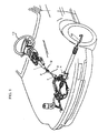
- Fig. 1 is an overall perspective view showing a steering apparatus according to the present invention in a state of being mounted on a vehicle.
- Fig. 2 is apartlysectional side elevation view showing principal parts of a steering apparatus according to a first embodiment of the present invention.
- Fig. 3 is an enlarged sectional view of a double Cardan constant velocity universal joint shown in Fig. 2, taken along line A-A thereof.
- Fig. 4 is a sectional viewof the double Cardan constant velocity universal joint in a state reached when a steering shaft in the state shown in Fig. 3 is rotated by 90 degrees.
- Fig. 5 is an enlarged sectional view of an elastic coupling shown in Fig. 2.
- Fig. 6 is a partly sectional side elevationviewshowing principal parts of a steering apparatus according to a second embodiment of the present invention.
- Fig. 7 is an exploded perspective view of an elastic coupling shown in Fig. 6.
- Fig. 8 is apartly sectional side elevationviewshowing principal parts of a steering apparatus according to a third embodiment of the present invention.
- Fig. 9 is a partly sectional side elevationview showing principal parts of a steering apparatus according to a fourth embodiment of the present invention.
- Fig. 10 is a cross-sectional view of a constant velocity universal joint shown in Fig. 9.
- Fig. 1 is an overall perspective view showing a steering apparatus according to the present invention in a state of being mounted on a vehicle.
- Fig. 2 is a partly sectional side elevation view showing principal parts of a steering apparatus according to the first embodiment of the present invention.
- Fig. 3 is an enlarged sectional view of a double Cardan constant velocity universal joint shown in Fig. 2, taken along line A--A thereof.
- Fig. 4 is a sectional view of the double Cardan constant velocity universal joint in a state reached when a steering shaft in the state shown in Fig. 3 is rotated by 90 degrees.
- Fig. 5 is an enlarged sectional view of an elastic coupling shown in Fig. 2.
- a cylindrical column 1 is fixed to a vehicle body and a steering shaft 12 is rotatably and axially supported by the column 1.
- a steering wheel 13 is connected to a right end (toward a rear of the vehicle body) of the steering shaft 12 and an intermediate shaft 3 is connected, via a Cardan joint 2, to a left end (toward a front of the vehicle body) of the steering shaft 12.
- a double Cardan constant velocity universal joint 4 is connected to a left end of the intermediate shaft 3, and an extension shaft 5 is connected to the double Cardan constant velocity universal joint 4.
- Constant velocity universal joints are available in such types as Birfield, tripot, double offset, cross groove, double Cardan, and Rzeppa. The following description of the first embodiment is based on a case in which a double Cardan constant velocity universal joint is used.
- a pinion 54 attached to a pinion shaft 53 which is connected to a lower end of the extension shaft 5 is engaged with a rack 61 of a steering gear 6.
- the extension shaft 5 includes an upper extension shaft 51, a lower extension shaft 52, and an elastic coupling 7, a lower end of the upper extension shaft 51 and an upper end of the lower extension shaft 52 being coupled by the elastic coupling 7.
- the elastic coupling 7 is provided at about an axial midpoint of the extension shaft 5.
- the pinion shaft 53 and the pinion 54 are not integral with the extension shaft 5. They are fixedly clamped to a coupling 523 formed at a lower end of the lower extension shaft 52.
- the intermediate shaft 3 includes an intermediate inner shaft 31 on which a male spline is formed and which is positioned toward the rear of the vehicle (upper side) and a hollow cylindrical intermediate outer shaft 32 on which a female spline is formed and which is positioned toward the front of the vehicle (lower side).
- the male spline of the intermediate inner shaft 31 is fit into the female spline of the intermediate outer shaft 32 such that the male spline is slidable along the female spline and such that a torque is transmissible from the male spline to the female spline.
- the end toward the rear of the vehicle of the intermediate inner shaft 31 is connected to the Cardan joint 2, and the end toward the front of the vehicle of the intermediate outer shaft 32 is connected to the double Cardan constant velocity universal joint 4.
- Figs. 3 and 4 show details of the double Cardan constant velocity universal joint 4.
- the double Cardan constant velocity universal joint 4 includes an intermediate housing 41, first and second yokes 42 and 43, a first spider 44 connecting the first yoke 42 to the intermediate housing 41, and a second spider 45 connecting the second yoke 43 to the intermediate housing 41.
- It is a double Cardan constant velocity universal joint which absorbs, by means of a sliding centering disc 46, changes in positional relationship among the first and second yokes 42 and 43 and the intermediate housing 41.
- the intermediate housing 41 is provided with a pair of first support arms 411 of a same phase at an axial end (right end as viewed in Figs. 3 and 4) and a pair of second support arms 412 of a same phase at the other axial end (left end as viewed in Figs. 3 and 4).
- the first support arms 411 are provided, in their edge portions, with a corresponding pair of mutually concentric first support holes 413.
- the second support arms 412 are provided, in their edge portions, with a corresponding pair of mutually concentric second support holes 414.
- the first yoke 42 has a coupling cylinder portion 421 to which an end portion toward the front of the vehicle of the intermediate outer shaft 32 can be fixed.
- a pair of third support arms 422 is provided at an axial end (left end as viewed in Figs. 3 and 4) of the coupling cylinder portion 421.
- a pair of mutually concentric third support holes 423 is formed in end portions of the third support arms 422, respectively.
- a spherical first engaging protrusion 425 protruding in a direction away from the coupling cylinder portion 421 is formed at an intermediate portion of a first connecting part 424 which connects ends of the third support arms 422.
- the second yoke 43 has a coupling cylinder portion 431 to which an upper end portion of the upper extension shaft 51 is fixable.
- a pair of fourth support arms 432 is provided at an axial end (right end as viewed in Figs. 3 and 4) of the coupling cylinder portion 431.
- a pair of mutually concentric fourth support holes 433 is formed in end portions of the fourth support arms 432, respectively.
- a spherical second engaging protrusion 435 protruding in a direction away from the coupling cylinder portion 431 is formed at an intermediate portion of a second connecting part 434 which connects ends of the fourth support arms 432.
- First and second axial portions 441 and 442 make up, in a state of being perpendicular to each other, the first spider 44. Ends of the first axial portion 441 are rotatably supported at inside the first support holes 413, respectively, by radial needle bearings 415. Ends of the second axial portion 442 are rotatably supported at inside the third support holes 423, respectively, by radial needle bearings 415.
- Third and fourth axial portions 451 and 452 make up, in a state of being perpendicular to each other, the second spider 45. Ends of the third axial portion 451 are rotatably supported at inside the second support holes 414, respectively, by radial needle bearings 415. Ends of the fourth axial portion 452 are rotatably supported at inside the fourth support holes 433, respectively, by radial needle bearings 415.
- the intermediate housing 41 includes a first intermediate housing element 416 which includes the first support arms 411 and a second intermediate housing element 417 which includes the second support arms 412, the first and second intermediate housing elements 416 and 417 being coupled by plural bolts 418.
- a space for sliding 419 is provided between the first and second intermediate housing elements 416 and 417.
- the centering disc 46 is disposed in the space for sliding 419 such that it is displaceable in a plane perpendicular to a central axis of the intermediate housing 41.
- First and second spherical engaging holes 461 and 462 are formed, in the same phase (concentrically), in axial end portions of the centering disc 46.
- the first and second engaging protrusions 425 and 435 are oscillatingly displaceably engaged with the first and second engaging holes 461and462, respectively.
- the engagement between the first and second engaging protrusions 425 and 435 and the first and second engaging holes 461 and 462 works to equalize the inclinations with respect to the intermediate housing 41 of the first and second yokes 42 and 43.
- the elastic coupling 7 includes, as shown in Fig. 5, an inner sleeve 71, an elastic body 72, an outer sleeve 73, and a stopper pin 74.
- the stopper pin 74 is a metallic pin which is fixed in an upper end portion of the lower extension shaft 52 in a diameter direction thereof. To allow the stopper pin 74 to be fixed as described above, a pair of through holes 521 facing each other in the diameter direction are formed in the upper end portion of the lower extension shaft 52.
- the stopper pin 74 inserted through the through holes 521 is supported at its two intermediate portions. Both end portions of the stopper pin 74 have an outer diameter slightly larger than the inner diameter of the through holes 521. In a state where the stopper pin 74 is fixed as described above, each end portion of the stopper pin 74 protrudes outward from an outer periphery of the lower extension shaft 52 in the diameter direction thereof.
- the elastic body 72 is made of an elastomeric material such as rubber and has a cylindrical shape.
- the metallic inner and outer sleeves 71 and 73 both having a cylindrical shape are concentrically disposed.
- An outer peripheral surface of the inner sleeve 71 and an inner peripheral surface of the elastic body 72 are bonded by heating or by using an adhesive.
- An inner peripheral surface of the outer sleeve 73 and an outer peripheral surface of the elastic body 72 are bonded in a similar way.
- the inner sleeve 71 is fixedly fitted onto an outer periphery 522 of an upper end portion of the lower extension shaft 52.
- the outer sleeve 73 is fixedly fitted in an inner periphery 512 of the upper extension shaft 51.
- each of through holes 711, 721, 731 and 511 formed at one pair each of locations in the inner sleeve 71, the elastic body 72, the outer sleeve 73 and a part of cylindrical portion 513 of the upper extension shaft 51.
- the one pair each of through holes are aligned straight with the through holes 521 formed in the lower extension shaft 52, each pair of the through holes facing each other in a diameter direction of the lower extension shaft 52.
- Two end portions of the stopper pin 74 supported by the lower extension shaft 52 are inserted in the through holes 711, 721, 731, and 511 formed in the inner sleeve 71, the elastic body 72, the outer sleeve 73, and the upper extension shaft 51, respectively.
- the through holes 711 formed in the inner sleeve 71 have an inner diameter approximately equal to the inner diameter of the through holes 521 formed in the lower extension shaft 52.
- the through holes 721 and 731 formed in the elastic body 72 and the outer sleeve 73, respectively, and the through holes 511 formed in the cylindrical portion 513 of the upper extension shaft 51 have an inner diameter larger than the inner diameter of the through holes 521 formed in the lower extension shaft 52.
- a gap is formed between an outer peripheral surface at each end portion of the stopper 74 and the inner peripheral surface of each of the corresponding one of the through holes 721 formed in the elastic body 72, the corresponding one of the through holes 731 formed in the outer sleeve 73, and the corresponding one of the through holes 511 formed in the upper extension shaft 51.
- the elastic coupling 7 configured as described above operates as follows.
- each end of the stopper pin 74 is positioned in a neutral position or in a position slightly shifted from the neutral position inside each of the through holes 511 formed in the upper extension shaft 51.
- the small torque is transmitted from the lower extension shaft 52 to the pinion shaft 53, the pinion 54, the rack 61, and the steering gear 6 via the outer sleeve 73, the elastic body 72, and the inner sleeve 71.
- the vibrations and bending moments applied to the pinion shaft 53 and the pinion 54 are reduced.
- steering stability is improved and the pinion shaft 53 is prevented from being subjected to a heavy load.
- disposing the elastic coupling 7 at about the axial midpoint of the extension shaft 5 makes it possible to appropriately restrain the amplitude of vibrations and the magnitude of bending moments applied to the pinion shaft 53.
- the pinion shaft 53 and the pinion 54 are not integral with the extension shaft 5, and the pinion shaft 53 is connected to the lower end of the lower extension shaft 52, the pinion shaft 53 and the pinion 54 may be configured to be integral with the lower extension shaft 52.
- the elastic coupling 7 is provided at about the axial midpoint of the extension shaft 5, but it may be disposed anywhere along the extension shaft 5, for example, at a point close to the pinion shaft 53 or at a point close to the double Cardan constant velocity universal joint 4.
- Fig. 6 which is equivalent to Fig. 2 for the first embodiment, is a partly sectional side elevation view showing principal parts of a steering apparatus according to the second embodiment of the present invention.
- Fig. 7 is an exploded perspective view of an elastic coupling shown in Fig. 6.
- the elastic coupling used in the first embodiment is of a stopper pin type.
- the elastic coupling used in the second embodiment is of a coupling type.
- a cylindrical column 1 is fixed to a vehicle body, and a steering shaft 12 is rotatably and axially supported by the column 1.
- a steering wheel 13 as shown in the first embodiment is connected to a right end (toward a rear of the vehicle) of the steering shaft 12.
- An intermediate shaft 3 is connected to a left end (toward a front of the vehicle) of the steering shaft 12 via a Cardan joint 2.
- a double Cardan constant velocity universal joint 4 which is identical in configuration with the one used in the first embodiment is connected to a left end of the intermediate shaft 3.
- An extension shaft 5 is connected to the double Cardan constant velocity universal joint 4.
- a pinion 54 attached to a pinion shaft 53 connected to a lower end of the extension shaft 5 is engaged with a rack 61 of a steering gear 6.
- the extension shaft 5 includes an upper extension shaft 51, a lower extension shaft 52, and an elastic coupling 7 of a coupling type, a lower end of the upper extension shaft 51 and an upper end of the lower extension shaft 52 being connected by the elastic coupling 7.
- the elastic coupling 7 of a coupling type is provided at a position closer, than an axial midpoint of the extension shaft 5, to an upper end thereof.
- the pinion shaft 53 and the pinion 54 are not integral with the extension shaft 5. They are fixedly clamped to a coupling 523 formed at a lower end of the lower extension shaft 52.
- the elastic coupling 7 of a coupling type used in the second embodiment includes a vibration-proof disc-shaped rubber 75 made of an elastomeric material such as rubber.
- a vibration-proof disc-shaped rubber 75 made of an elastomeric material such as rubber.
- Four bolt through-holes are formed through, along a left-to-right direction as viewed in Fig. 7, the vibration-proof rubber 75 to be 90 degrees apart.
- Metallic cylindrical members 751a to 751d are fit in the bolt through-holes, respectively.
- a pair of the cylindrical members 751a and 751b opposed to each other are fit such that they protrude from a left face of the vibration-proof rubber 75.
- a pair of the cylindrical members 751c and 751d opposed to each other is fit such that they protrude from a right face of the vibration-proof rubber 75.
- Plastic collars 77a to 77d are fit onto outer peripheries of protruding portions of the cylindrical members 751a to 751d, respectively, the plastic collars 77a to 77d being about as high as the protruding portions.
- the lower extension shaft 52 and the upper extension shaft 51 are connected to each other using the elastic coupling 7.
- a metallic stopper plate 76a having notched portions 761a and 761b corresponding to the plastic collars 77a and 77b is fit between the lower extension shaft 52 and the vibration-proof rubber 75
- a metallic stopper plate 76b having notched portions 761c and 761d corresponding to the plastic collars 77c and 77d is fit between the upper extension shaft 51 and the vibration-proof rubber 75.
- a pair of bolt holes 762c and 762d are formed on both sides of a pair of the notched portions 761a and 761b of the stopper plate 76a, the bolt holes 762c and 762d corresponding to a pair of the cylindrical members 751c and 751d.
- a pair of bolt holes 762a and 762b are formed on both sides of a pair of the notched portions 761c and 761d of the stopper plate 76b, the bolt holes 762a and 762b corresponding to a pair of the cylindrical members 751a and 751b.
- the stopper plates 76a and 76b are to prevent the vibration-proof rubber 75 from being twisted when the extension shaft 5 rotates.
- the notched portions 761a to 761d abut against the plastic collars 77a to 77d, respectively, to restrict turning of the vibration-proof rubber 75.
- a flange 524 to be fixed to the vibration-proof rubber 75 is formed integrally with the lower extension shaft 52.
- a pair of bolt through-holes 525a and 525b is formed in two end portions of the flange 524, respectively.
- a flange 514 to be fixed to the vibration-proof rubber 75 is formed integrally with the upper extension shaft 51.
- a pair of bolt through-holes 515c and 515d is formed in two end portions of the flange 514, respectively.
- the flange 524 of the lower extension shaft 52 is positioned on the cylindrical members 751a and 751b protruding from the left face of the vibration-proof rubber 75, then bolts 79a and 79b are inserted, respectively, through the bolt through-holes 525a and 525b formed in the flange 524.
- the bolts 79a and 79b are then further inserted through the cylindrical members 751a and 751b fit in the vibration-proof rubber 75 and the bolt holes 762a and 762b formed in the stopper plate 76b disposed on the right face of the vibration-proof rubber 75.
- nuts 78a and 78b are fixedly screwed to threaded end portions of the bolts 79a and 79b, respectively.
- the bolt through-holes 515c and 515d formed in the flange 514 of the upper extension shaft 51 are aligned with the cylindrical members 751c and 751d protruding from the right face of the vibration-proof rubber 75, then bolts 79c and 79d are inserted, respectively, through the boltthrough-holes515c and 515d formed in the flange 524.
- the bolts 79c and 79d are then further inserted through the cylindrical members 751c and 751d fit in the vibration-proof rubber 75 and the bolt holes 762c and 762d formed in the stopper plate 76a disposed on the left face of the vibration-proof rubber 75.
- nuts 78c and 78d are fixedly screwed to threaded end portions of the bolts 79c and 79d, respectively.
- Fig. 8 which is equivalent to Fig. 2 for the first embodiment, is a partly sectional side elevation view of a steering apparatus according to the third embodiment of the present invention.
- Fig. 8 which is equivalent to Fig. 2 for the first embodiment, is a partly sectional side elevation view of a steering apparatus according to the third embodiment of the present invention.
- Only parts of the steering apparatus of the present embodiment configured differently from those used in the foregoing embodiments will be described. Description which duplicates the foregoing description will be omitted. Parts identical with those used in the foregoing embodiments will be denoted by the same reference numerals as used in describing the foregoing embodiments.
- the third embodiment represents a case in which a variable gear ratio steering (VGRS) device is provided between a double Cardan constant velocity universal joint 4 and an extension shaft 5, thevariablegearratiosteering (VGRS) device being for changing a ratio between a steering angle of a steering wheel and a turning angle of front wheels, that is, a steering angle ratio depending on the running speed of a vehicle.
- VGRS variable gear ratio steering
- a cylindrical column 1 is fixed to a vehicle body, and a steering shaft 12 is rotatably and axially supported by the column 1.
- a steering wheel 13 as shown in the first embodiment is connected to a right end (toward a rear of the vehicle) of the steering shaft 12.
- An intermediate shaft 3 is connected to a left end (toward a front of the vehicle) of the steering shaft 12 via a Cardan joint 2.
- a double Cardan constant velocity universal joint 4 which is identical in configuration with the one used in the first embodiment is connected to a left end of the intermediate shaft 3.
- An extension shaft 5 is connected to the double Cardan constant velocity universal joint 4.
- a pinion 54 formed at a lower end of the extension shaft 5 integrally therewith is engaged with a rack 61 of a steering gear 6.
- the extension shaft 5 includes an upper extension shaft 51, a lower extension shaft 52, and an elastic coupling 7 which is identical in configuration with the elastic coupling 7 used in the second embodiment, a lower end of the upper extension shaft 51 and an upper end of the lower extension shaft 52 being connected by the elastic coupling 7.
- the elastic coupling 7 of a coupling type is provided at a position closer, than an axial midpoint of the extension shaft 5, to a lower end thereof.
- variable gear ratio steering (VGRS) device 8 is mounted at about an axial midpoint of the upper extension shaft 51.
- the variable gear ratio steering (VGRS) device 8 internally includes a differential transmission mechanism such as a harmonic drive gearing mechanism for speed reduction, for example, like the one disclosed in JP-A No. 211541/2000 or a planetary gear mechanism. It is a device to continuously change a steering angle ratio according to the running speed of a vehicle, decreasing the turning angle of the steering wheel when the vehicle is running at low speed and increasing the turning angle of the steering wheel when the vehicle is running at high speed.
- Fig. 9 which is equivalent to Fig. 2 for the first embodiment, is a partly sectional side elevation view of a steering apparatus according to the fourth embodiment of the present invention.
- Fig. 10 is a cross-sectional view of a constant velocity universal joint shown in Fig. 9.
- a Rzeppa constant velocity universal joint is used instead of the double Cardan constant velocityuniversal joint 4 used in the foregoing embodiments.
- a cylindrical column 1 is fixed to a vehicle body, and a steering shaft 12 is rotatably and axially supported by the column 1.
- a steering wheel 13 as shown in the first embodiment is connected to a right end (toward a rear of the vehicle) of the steering shaft 12.
- An intermediate shaft 3 is connected to a left end (toward a front of the vehicle) of the steering shaft 12 via a Cardan joint 2.
- a Rzeppa constant velocity universal joint 47 is connected to a left end of the intermediate shaft 3.
- An extension shaft 5 is connected to the Rzeppa constant velocity universal joint 47.
- a pinion 54 formed at a lower end of the extension shaft 5 integrally therewith is engaged with a rack 61 of a steering gear 6.
- the extension shaft 5 includes an upper extension shaft 51, a lower extension shaft 52, and an elastic coupling 7 which is identical in configuration with the elastic coupling 7 used in the second embodiment, a lower end of the upper extension shaft 51 and an upper end of the lower extension shaft 52 being connected by the elastic coupling 7.
- the elastic coupling 7 of a coupling type is provided at about an axial midpoint of the extension shaft 5.
- an Oldham's coupling may be disposed on the intermediate shaft 3 or on the extension shaft 5 instead of using a Cardan joint 2.
- Fig. 10 is a detailed sectional view of the Rzeppa constant velocity universal joint 47.
- a spherical inner coupling member 471 is formed at an upper end of the upper extension shaft 51 integrally therewith.
- a ball guide groove 472 is formed on the spherical surface of the inner coupling member 471.
- An outer coupling member 473 having a spherical concave portion is formed at a lower end of an intermediate outer shaft 32 integrally therewith, the intermediate outer shaft 32 being included in the intermediate shaft 3.
- a ball guide groove 474 is formed in the concave portion.
- Plural torque transmitting balls 475 are rollably fit in the ball guide grooves 472 and 474, enabling torque transmission between the inner coupling member 471 and the outer coupling member 473.
- a ball retainer 476 having an inner surface complementary to the spherical surface of the inner coupling member 471 can rotate about a center of sphere of the inner coupling member 471 while retaining the torque transmitting balls 475.
- the Cardan joint 2 may be omitted in cases where the steering shaft 12 and the intermediate inner shaft 31 can be arranged straightway with no assembly error.
- the embodiment may also be applied to a steering apparatus which allows at least either one of a tilted position or a telescopic position of the steering wheel 13 to be adjusted.
Landscapes
- Engineering & Computer Science (AREA)
- General Engineering & Computer Science (AREA)
- Mechanical Engineering (AREA)
- Chemical & Material Sciences (AREA)
- Combustion & Propulsion (AREA)
- Transportation (AREA)
- Physics & Mathematics (AREA)
- Acoustics & Sound (AREA)
- Aviation & Aerospace Engineering (AREA)
- Steering Controls (AREA)
- Steering-Linkage Mechanisms And Four-Wheel Steering (AREA)
Applications Claiming Priority (1)
| Application Number | Priority Date | Filing Date | Title |
|---|---|---|---|
| JP2005016070A JP2006199249A (ja) | 2005-01-24 | 2005-01-24 | ステアリング装置 |
Publications (1)
| Publication Number | Publication Date |
|---|---|
| EP1683703A1 true EP1683703A1 (fr) | 2006-07-26 |
Family
ID=36147630
Family Applications (1)
| Application Number | Title | Priority Date | Filing Date |
|---|---|---|---|
| EP06001216A Withdrawn EP1683703A1 (fr) | 2005-01-24 | 2006-01-20 | Arbre de direction avec un dispositif d'accouplement elastique |
Country Status (3)
| Country | Link |
|---|---|
| US (1) | US20060163860A1 (fr) |
| EP (1) | EP1683703A1 (fr) |
| JP (1) | JP2006199249A (fr) |
Cited By (2)
| Publication number | Priority date | Publication date | Assignee | Title |
|---|---|---|---|---|
| EP3163107A1 (fr) * | 2015-10-27 | 2017-05-03 | Josef Hohn GmbH | Arbre de transmission |
| EP3282142A1 (fr) * | 2016-08-08 | 2018-02-14 | Benzi & Di Terlizzi s.r.l. | Grand-angle joint homocinétique |
Families Citing this family (3)
| Publication number | Priority date | Publication date | Assignee | Title |
|---|---|---|---|---|
| DE102012101388A1 (de) * | 2012-02-21 | 2013-08-22 | Thyssenkrupp Presta Aktiengesellschaft | Lenkwelle für ein Kraftfahrzeug |
| DE102016001585A1 (de) | 2016-02-11 | 2017-08-17 | Trw Automotive Gmbh | Fahrzeuginsassen-Rückhaltevorrichtung |
| KR20230090519A (ko) * | 2021-12-15 | 2023-06-22 | 남양넥스모 주식회사 | 차량 조향장치용 인터미디어트 샤프트 |
Citations (11)
| Publication number | Priority date | Publication date | Assignee | Title |
|---|---|---|---|---|
| US4179137A (en) * | 1978-08-28 | 1979-12-18 | General Motors Corporation | Adjustable steering column for vehicles |
| JPS6152421A (ja) * | 1984-08-20 | 1986-03-15 | Mazda Motor Corp | ステアリング機構の連結装置 |
| US5419740A (en) * | 1992-03-16 | 1995-05-30 | Toyota Jidosha Kabushiki Kaisha | Constant velocity joint having centering disk bearing eccentric socket |
| US5435785A (en) * | 1992-03-06 | 1995-07-25 | Nacam | Elasting coupling unit especially for a vehicle steering column |
| JPH0930429A (ja) * | 1995-07-24 | 1997-02-04 | Toyota Motor Corp | 自動車用操舵装置 |
| JPH10318273A (ja) * | 1997-05-20 | 1998-12-02 | Nippon Seiko Kk | 弾性軸継手 |
| US5941776A (en) * | 1996-08-23 | 1999-08-24 | Daimler-Benz Aktiengesellschaft | Steering system for a motor vehicle having a lower steering spindle |
| DE10064439A1 (de) * | 2000-12-22 | 2002-06-27 | Volkswagen Ag | Lenkungsgelenkwelle |
| JP2003327136A (ja) * | 2002-05-15 | 2003-11-19 | Toyoda Mach Works Ltd | 車両用操舵装置 |
| WO2004113150A1 (fr) * | 2003-06-20 | 2004-12-29 | Nsk Ltd. | Dispositif de direction de vehicule automobile |
| WO2005005850A1 (fr) * | 2003-07-11 | 2005-01-20 | Nsk Ltd. | Dispositif de direction pour vehicule |
Family Cites Families (11)
| Publication number | Priority date | Publication date | Assignee | Title |
|---|---|---|---|---|
| FR2620413A1 (fr) * | 1987-09-10 | 1989-03-17 | Seamet International | Element constitutif d'une ligne d'ancrage catenaire, ligne d'ancrage comportant un tel element, et dispositif et procede de mise en oeuvre de cette ligne d'ancrage |
| FR2699976B1 (fr) * | 1992-12-30 | 1996-07-26 | Castellon Melchor Daumal | Arbre telescopique. |
| DE19522389C1 (de) * | 1995-06-23 | 1996-09-19 | Daimler Benz Ag | Sicherheitslenksäule |
| JP4219472B2 (ja) * | 1999-03-12 | 2009-02-04 | Ntn株式会社 | 等速自在継手 |
| JP3517833B2 (ja) * | 2000-04-05 | 2004-04-12 | 本田技研工業株式会社 | 可変舵角比操舵装置及び電動パワーステアリング装置を有する車両 |
| JP4130294B2 (ja) * | 2000-07-18 | 2008-08-06 | 日本精工株式会社 | ステアリング用弾性軸継手 |
| JP4710202B2 (ja) * | 2001-08-31 | 2011-06-29 | トヨタ自動車株式会社 | 電動式パワーステアリング装置 |
| JP2003237590A (ja) * | 2002-02-20 | 2003-08-27 | Toyoda Mach Works Ltd | 伝達比可変機構 |
| US7322607B2 (en) * | 2002-06-11 | 2008-01-29 | Nsk Ltd. | Telescopic shaft for steering vehicle and telescopic shaft for steering vehicle with cardan shaft coupling |
| JP2005280678A (ja) * | 2004-03-04 | 2005-10-13 | Nsk Ltd | ステアリング装置 |
| JP4639769B2 (ja) * | 2004-11-18 | 2011-02-23 | 日産自動車株式会社 | 車両のトルクステア抑制構造 |
-
2005
- 2005-01-24 JP JP2005016070A patent/JP2006199249A/ja active Pending
-
2006
- 2006-01-18 US US11/334,527 patent/US20060163860A1/en not_active Abandoned
- 2006-01-20 EP EP06001216A patent/EP1683703A1/fr not_active Withdrawn
Patent Citations (12)
| Publication number | Priority date | Publication date | Assignee | Title |
|---|---|---|---|---|
| US4179137A (en) * | 1978-08-28 | 1979-12-18 | General Motors Corporation | Adjustable steering column for vehicles |
| JPS6152421A (ja) * | 1984-08-20 | 1986-03-15 | Mazda Motor Corp | ステアリング機構の連結装置 |
| US5435785A (en) * | 1992-03-06 | 1995-07-25 | Nacam | Elasting coupling unit especially for a vehicle steering column |
| US5419740A (en) * | 1992-03-16 | 1995-05-30 | Toyota Jidosha Kabushiki Kaisha | Constant velocity joint having centering disk bearing eccentric socket |
| JPH0930429A (ja) * | 1995-07-24 | 1997-02-04 | Toyota Motor Corp | 自動車用操舵装置 |
| US5941776A (en) * | 1996-08-23 | 1999-08-24 | Daimler-Benz Aktiengesellschaft | Steering system for a motor vehicle having a lower steering spindle |
| JPH10318273A (ja) * | 1997-05-20 | 1998-12-02 | Nippon Seiko Kk | 弾性軸継手 |
| DE10064439A1 (de) * | 2000-12-22 | 2002-06-27 | Volkswagen Ag | Lenkungsgelenkwelle |
| JP2003327136A (ja) * | 2002-05-15 | 2003-11-19 | Toyoda Mach Works Ltd | 車両用操舵装置 |
| WO2004113150A1 (fr) * | 2003-06-20 | 2004-12-29 | Nsk Ltd. | Dispositif de direction de vehicule automobile |
| EP1637433A1 (fr) * | 2003-06-20 | 2006-03-22 | NSK Ltd. | Dispositif de direction de vehicule automobile |
| WO2005005850A1 (fr) * | 2003-07-11 | 2005-01-20 | Nsk Ltd. | Dispositif de direction pour vehicule |
Non-Patent Citations (4)
| Title |
|---|
| PATENT ABSTRACTS OF JAPAN vol. 010, no. 211 (M - 501) 24 July 1986 (1986-07-24) * |
| PATENT ABSTRACTS OF JAPAN vol. 1997, no. 06 30 June 1997 (1997-06-30) * |
| PATENT ABSTRACTS OF JAPAN vol. 1999, no. 03 31 March 1999 (1999-03-31) * |
| PATENT ABSTRACTS OF JAPAN vol. 2003, no. 12 5 December 2003 (2003-12-05) * |
Cited By (2)
| Publication number | Priority date | Publication date | Assignee | Title |
|---|---|---|---|---|
| EP3163107A1 (fr) * | 2015-10-27 | 2017-05-03 | Josef Hohn GmbH | Arbre de transmission |
| EP3282142A1 (fr) * | 2016-08-08 | 2018-02-14 | Benzi & Di Terlizzi s.r.l. | Grand-angle joint homocinétique |
Also Published As
| Publication number | Publication date |
|---|---|
| JP2006199249A (ja) | 2006-08-03 |
| US20060163860A1 (en) | 2006-07-27 |
Similar Documents
| Publication | Publication Date | Title |
|---|---|---|
| EP3305563A1 (fr) | Système de direction de véhicule | |
| US7578744B2 (en) | Slip joint for use in steering system | |
| WO2008056636A1 (fr) | Arbre de direction de véhicule et dispositif de direction de véhicule | |
| EP1834105B1 (fr) | Ensemble de palier intermediaire conçu pour supporter par rotation un arbre a des d'angles variant par rapport a une surface de support | |
| US6022047A (en) | Universal joint and a yoke therefor for a steering apparatus | |
| KR20180089629A (ko) | 전동식 동력 보조 조향장치의 감속기 | |
| US8506413B2 (en) | Rotary connector | |
| EP1683703A1 (fr) | Arbre de direction avec un dispositif d'accouplement elastique | |
| US20090203455A1 (en) | Extendable Shaft and Motor Vehicle Steering Apparatus | |
| JPH01169123A (ja) | 継手装置 | |
| US6062982A (en) | Force transmitting apparatus | |
| US20080248883A1 (en) | Universal Joint | |
| WO2005005850A1 (fr) | Dispositif de direction pour vehicule | |
| JPS61160629A (ja) | 弾性軸継手 | |
| KR101989913B1 (ko) | 자동차용 조향축 | |
| JP3446488B2 (ja) | ダブルカルダン式等速ジョイント | |
| JP3446541B2 (ja) | ダブルカルダン式等速ジョイント | |
| CN100451370C (zh) | 车辆转向装置 | |
| CN101094995A (zh) | 中心轴承组件 | |
| US20060037425A1 (en) | Shaft assembly for use in steering systems | |
| JPH0972348A (ja) | ユニバーサルジョイント | |
| JPH09229085A (ja) | 弾性軸継手 | |
| JPH10325418A (ja) | 弾性軸継手 | |
| KR20190038133A (ko) | 전동식 동력 보조 조향장치의 감속기 | |
| KR20230090519A (ko) | 차량 조향장치용 인터미디어트 샤프트 |
Legal Events
| Date | Code | Title | Description |
|---|---|---|---|
| PUAI | Public reference made under article 153(3) epc to a published international application that has entered the european phase |
Free format text: ORIGINAL CODE: 0009012 |
|
| 17P | Request for examination filed |
Effective date: 20060120 |
|
| AK | Designated contracting states |
Kind code of ref document: A1 Designated state(s): AT BE BG CH CY CZ DE DK EE ES FI FR GB GR HU IE IS IT LI LT LU LV MC NL PL PT RO SE SI SK TR |
|
| AX | Request for extension of the european patent |
Extension state: AL BA HR MK YU |
|
| 17Q | First examination report despatched |
Effective date: 20070306 |
|
| AKX | Designation fees paid |
Designated state(s): DE FR GB |
|
| GRAP | Despatch of communication of intention to grant a patent |
Free format text: ORIGINAL CODE: EPIDOSNIGR1 |
|
| RTI1 | Title (correction) |
Free format text: VEHICLE COMPRISING A STEERING APPARATUS WITH AN ELASTIC COUPLING |
|
| STAA | Information on the status of an ep patent application or granted ep patent |
Free format text: STATUS: THE APPLICATION IS DEEMED TO BE WITHDRAWN |
|
| 18D | Application deemed to be withdrawn |
Effective date: 20090303 |