EP1684130B1 - Récipient d`approvisionnement en révélateur et appareil de formation d`image - Google Patents
Récipient d`approvisionnement en révélateur et appareil de formation d`image Download PDFInfo
- Publication number
- EP1684130B1 EP1684130B1 EP05024603A EP05024603A EP1684130B1 EP 1684130 B1 EP1684130 B1 EP 1684130B1 EP 05024603 A EP05024603 A EP 05024603A EP 05024603 A EP05024603 A EP 05024603A EP 1684130 B1 EP1684130 B1 EP 1684130B1
- Authority
- EP
- European Patent Office
- Prior art keywords
- image forming
- forming apparatus
- main assembly
- container
- developer supply
- Prior art date
- Legal status (The legal status is an assumption and is not a legal conclusion. Google has not performed a legal analysis and makes no representation as to the accuracy of the status listed.)
- Expired - Lifetime
Links
Images









Classifications
-
- G—PHYSICS
- G03—PHOTOGRAPHY; CINEMATOGRAPHY; ANALOGOUS TECHNIQUES USING WAVES OTHER THAN OPTICAL WAVES; ELECTROGRAPHY; HOLOGRAPHY
- G03G—ELECTROGRAPHY; ELECTROPHOTOGRAPHY; MAGNETOGRAPHY
- G03G15/00—Apparatus for electrographic processes using a charge pattern
- G03G15/06—Apparatus for electrographic processes using a charge pattern for developing
- G03G15/08—Apparatus for electrographic processes using a charge pattern for developing using a solid developer, e.g. powder developer
- G03G15/0822—Arrangements for preparing, mixing, supplying or dispensing developer
- G03G15/0877—Arrangements for metering and dispensing developer from a developer cartridge into the development unit
- G03G15/0881—Sealing of developer cartridges
- G03G15/0886—Sealing of developer cartridges by mechanical means, e.g. shutter, plug
-
- G—PHYSICS
- G03—PHOTOGRAPHY; CINEMATOGRAPHY; ANALOGOUS TECHNIQUES USING WAVES OTHER THAN OPTICAL WAVES; ELECTROGRAPHY; HOLOGRAPHY
- G03G—ELECTROGRAPHY; ELECTROPHOTOGRAPHY; MAGNETOGRAPHY
- G03G15/00—Apparatus for electrographic processes using a charge pattern
- G03G15/06—Apparatus for electrographic processes using a charge pattern for developing
-
- G—PHYSICS
- G03—PHOTOGRAPHY; CINEMATOGRAPHY; ANALOGOUS TECHNIQUES USING WAVES OTHER THAN OPTICAL WAVES; ELECTROGRAPHY; HOLOGRAPHY
- G03G—ELECTROGRAPHY; ELECTROPHOTOGRAPHY; MAGNETOGRAPHY
- G03G15/00—Apparatus for electrographic processes using a charge pattern
- G03G15/06—Apparatus for electrographic processes using a charge pattern for developing
- G03G15/08—Apparatus for electrographic processes using a charge pattern for developing using a solid developer, e.g. powder developer
- G03G15/0822—Arrangements for preparing, mixing, supplying or dispensing developer
- G03G15/0865—Arrangements for supplying new developer
- G03G15/0867—Arrangements for supplying new developer cylindrical developer cartridges, e.g. toner bottles for the developer replenishing opening
- G03G15/0868—Toner cartridges fulfilling a continuous function within the electrographic apparatus during the use of the supplied developer material, e.g. toner discharge on demand, storing residual toner, acting as an active closure for the developer replenishing opening
-
- G—PHYSICS
- G03—PHOTOGRAPHY; CINEMATOGRAPHY; ANALOGOUS TECHNIQUES USING WAVES OTHER THAN OPTICAL WAVES; ELECTROGRAPHY; HOLOGRAPHY
- G03G—ELECTROGRAPHY; ELECTROPHOTOGRAPHY; MAGNETOGRAPHY
- G03G15/00—Apparatus for electrographic processes using a charge pattern
- G03G15/06—Apparatus for electrographic processes using a charge pattern for developing
- G03G15/08—Apparatus for electrographic processes using a charge pattern for developing using a solid developer, e.g. powder developer
- G03G15/0822—Arrangements for preparing, mixing, supplying or dispensing developer
- G03G15/0865—Arrangements for supplying new developer
- G03G15/0875—Arrangements for supplying new developer cartridges having a box like shape
-
- G—PHYSICS
- G03—PHOTOGRAPHY; CINEMATOGRAPHY; ANALOGOUS TECHNIQUES USING WAVES OTHER THAN OPTICAL WAVES; ELECTROGRAPHY; HOLOGRAPHY
- G03G—ELECTROGRAPHY; ELECTROPHOTOGRAPHY; MAGNETOGRAPHY
- G03G2215/00—Apparatus for electrophotographic processes
- G03G2215/06—Developing structures, details
- G03G2215/066—Toner cartridge or other attachable and detachable container for supplying developer material to replace the used material
- G03G2215/0663—Toner cartridge or other attachable and detachable container for supplying developer material to replace the used material having a longitudinal rotational axis, around which at least one part is rotated when mounting or using the cartridge
- G03G2215/0665—Generally horizontally mounting of said toner cartridge parallel to its longitudinal rotational axis
- G03G2215/067—Toner discharging opening covered by arcuate shutter
-
- G—PHYSICS
- G03—PHOTOGRAPHY; CINEMATOGRAPHY; ANALOGOUS TECHNIQUES USING WAVES OTHER THAN OPTICAL WAVES; ELECTROGRAPHY; HOLOGRAPHY
- G03G—ELECTROGRAPHY; ELECTROPHOTOGRAPHY; MAGNETOGRAPHY
- G03G2215/00—Apparatus for electrophotographic processes
- G03G2215/06—Developing structures, details
- G03G2215/066—Toner cartridge or other attachable and detachable container for supplying developer material to replace the used material
- G03G2215/0692—Toner cartridge or other attachable and detachable container for supplying developer material to replace the used material using a slidable sealing member, e.g. shutter
Definitions
- the present invention relates to a developer supply container for supplying a powdery developer to an electrophotographic image forming apparatus for forming an image with the developer, and the image forming apparatus using the developer supply container.
- the electrophotographic image forming apparatus is an image forming apparatus for forming an image on a recording medium in accordance with an electrophotographic image forming method.
- the electrophotographic image forming apparatus may include an electrophotographic copying machine, electrophotographic printers (such as a laser beam printer and an LED (light emitting diode) printer), a facsimile apparatus, a word processor, etc.
- a latent image is formed by selectively exposing an electrically uniformly charged surface of a photosensitive drum to light and is developed with a developer to form a developer image. Then, the developer image is transferred onto a recording medium to effect image recording.
- the developer is required to be supplied every time the developer is used up.
- a developer supply container for supplying the developer to the image forming apparatus is roughly classified into a so-called simultaneous supply-type developer supply container which supply the whole amount of developer contained in the developer supply container to a developer receiving container of a main assembly of the image forming apparatus at the same time and a stationary-type developer supply container which is mounted into the image forming apparatus main assembly, left standing as it is, and gradually supplies the developer to a developing apparatus until the developer is used up.
- a developer supply container (hereinafter also referred to as a "toner cartridge”) is replaced by demounting it from the image forming apparatus and mounting a new one into the image forming apparatus, so that (fresh) toner is supplied to the image forming apparatus.
- the toner as the developer is very fine powder, so that there has arisen such a problem that the toner scatters from a minute spacing between constitutional parts due to operational vibrations or the like during a toner supply operation, thus contaminating a user or surrounding parts with the toner.
- a developer supply container is mounted inside a main assembly of image forming apparatus and toner is discharged little by little from a small opening has been proposed and put into practical use.
- the image forming apparatus is provided with a buffer portion, as a toner containing portion, for temporarily storing the toner.
- a metering screw for stirring the toner and feeding a predetermined amount of toner corresponding to a degree of rotation and a conveyance screw, disposed downstream from the metering screw, for conveying the toner by being rotated always during recording (image formation) are disposed so as to supply a necessary amount of toner to a process cartridge.
- the image forming apparatus detects that the toner cartridge is empty and provides notification, to a user, that the developer supply container should be replaced with new one. In accordance with this notification, the user removes the (old) empty developer supply container from the image forming apparatus and inserts a new developer supply container into the image forming apparatus in place of the empty developer supply container, so that the image forming apparatus is capable of further continuing an image forming operation.
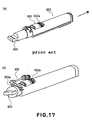
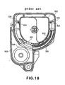
- Japanese Laid-Open Patent Application No. 2000-162861 has disclosed, as an example of a conventional developer supply container, such a constitution that a shutter of a developer supply container is opened and closed through a rotational force transmission member provided in a main assembly of an image forming apparatus, as shown in Figures 16 and 17.
- an image forming apparatus is provided with an open/close portion 501 at a side surface of a main assembly 500 of the image forming apparatus, so that a developer supply container (toner cartridge) 600 is mounted and demounted from the side surface of the image forming apparatus.
- the toner cartridge 600 has, as shown in Figure 17(a), a developer discharge opening 601 ( Figure 18) sealed or covered with a container shutter 602.
- the container shutter 602 is constituted so that it is not readily opened even when a user rotationally moves it in a simple one direction outside the main assembly, thus preventing toner from contaminating surrounding parts or portions due to erroneous leakage.
- a buffer portion 503 of the apparatus main assembly 500 is provided with a developer receiving opening 504 opposite to the developer discharge opening 601.
- the developer receiving opening 504 is provided with an apparatus shutter 505 for preventing contamination when the toner cartridge 600 is not mounted.
- the container shutter 602 and the apparatus shutter 505 are engaged with each other by mounting the toner cartridge 600 into the main assembly 500 to perform an open/close operation in an integrated state.
- an image forming apparatus is provided with a toner cartridge cover 23 at an upper surface thereof and a toner cartridge 31 is mounted from above the image forming apparatus.
- a toner cartridge 31 is mounted from above the image forming apparatus.
- an unshown container shutter and an unshown apparatus shutter are opened and closed by rotationally driving a handle 36 in place of the knob 603.
- gears are used as a driving force relay portion for transmitting a driving force from the handle 36 to the container shutter or the apparatus shutter.
- a gear train stepped gears
- an overlapping manner as seen in a rotational axis direction is different.
- other gears are mounted to and demounted from both ends of the gear train in order to relay the driving force as described above, depending on a state of the gear train, deviation in positional relationship (phase) between a handle and a shutter connected to the both end of the gear train is caused to occur.
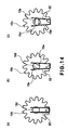
- a teeth a1 of a gear 506a and a teeth b1 of a gear 506b have the same phase.
- a teeth a4 of the gear 506a and a teeth b4 of the gear 506b are 9.6 degrees out of phase with each other. Accordingly, a handle and a shutter member connected through the gear train including this stepped gear also cause phase difference therebetween. As a result, an opening and closing (open/close) operation of the shutter member is out of a range which is originally intended.
- a rotational movement range of the handle 36 is restricted so as not to interfere an adjacent toner cartridge.
- the apparatus shutter is not sufficiently closed by the restricted rotational movement and that the apparatus shutter runs against an opposite closing position before the handle is rotationally moved in a predetermined amount of rotation, so that the handle cannot be rotationally moved to prevent the toner cartridge from being removed from the main assembly of the image forming apparatus.
- the developer receiving opening of the image forming apparatus main assembly remains open.
- An object of the present invention is to provide a developer supply container, detachably mountable to a main assembly of an image forming apparatus, capable of preventing a first driving force transmitting portion for opening and closing a developer discharge opening and a second driving force transmitting portion, which are connected via a driving force relay portion provided to the image forming apparatus main assembly, from deviating from a predetermined position to be engaged with a gear of the main assembly.
- Another object of the present invention is to provide an image forming apparatus to which the developer supply container is detachably mountable.
- a developer supply container capable of supplying a developer to a portion, to be supplied with the developer, of a main assembly of an image forming apparatus by being mounted into the image forming apparatus main assembly to permit transmission of a driving force between the developer supply container and the image forming apparatus main assembly, the developer supply container comprising:
- an image forming apparatus to which a developer supply container is detachably mountable, capable of supplying a developer to a portion to be supplied with the developer of a main assembly of the image forming apparatus by performing transmission of a driving force between a mounted developer supply container and the main assembly of the image forming apparatus, the image forming apparatus comprising:
- a main assembly 100 of an image forming apparatus according to this embodiment and a developer supply container to be mounted into the image forming apparatus main assembly 100 will be described with reference to the drawings.
- a general structure of the image forming apparatus main assembly 100 will be described with reference to Figures 1 and 2.
- Figure 1(a) is a schematic sectional view of the image forming apparatus main assembly 100 of this embodiment as seen in a left side surface of the image forming apparatus;
- Figure 1(b) is a conceptual view showing a conveyance process of developer from the developer supply container to the image forming apparatus main assembly 100;
- Figure 2(a) is an external perspective view of the image forming apparatus main assembly 100;
- Figure 2(b) is an external perspective view for illustrating a state of the image forming apparatus main assembly 100 during replacement of the developer supply container.
- a front surface of the image forming apparatus is located on a right side on the drawing. Further, as shown in Figure 2(a), the image forming apparatus is provided with a display operation portion 24 at an upper portion thereof, so that a housing cover 21, a sheet (paper) feeding cassette 13, and the like for releasing a conveyance path for paper jam treatment are operable from the front surface of the image forming apparatus.
- the image forming apparatus is a four drum-type (in-line) printer and achieves high speed by utilizing the four drums.
- the photosensitive drums 1a to 1d and developing devices 3a to 3d are disposed, in series in a substantially horizontal direction, vertically below the intermediary transfer belt 6, and are used for forming images of yellow, magenta, cyan, and black, respectively.
- a toner cartridge (e.g., a toner cartridge 31) as an example of each of developer supply containers for supplying developer to the developing devices 3a to 3d, respectively, is constituted so that it can be replaced from above the image forming apparatus.
- a surface of each of the photosensitive drums 1a to 1d is electrically charged uniformly by an associated one of charging apparatuses 2a to 2d. Thereafter, on the surface of each photosensitive drum, a latent image is formed by an associated one of exposure apparatuses 4a to 4d and is developed with developer to form an associated color toner image.
- the resultant four color toner images formed on the (four) photosensitive drums 1a to 1d are primary-transferred onto the intermediary transfer belt 6 in a superposition manner by primary transfer rollers 5a to 5d, respectively, thus forming a (full-) color toner image.
- the intermediary transfer belt 6 is extended under tension around a drive roller 7, a follower roller 8, and a tension roller 9 and is rotated around these rollers.
- the toner image on the intermediary transfer belt 6 is secondary-transferred onto a sheet by a secondary transfer roller 10.
- the sheet has been fed from a sheet feeding cassette 13 by a pickup roller 14 and conveyed to a secondary transfer portion while being timed to rotation of the intermediary transfer belt 6 by a pair of registration rollers 15.
- the sheet onto which the color toner image is transferred is subjected to application of heat and pressure by a fixing device 11 to fix the color toner image thereon, followed by discharge out of the image forming apparatus.
- toner cartridges 31 into which fresh developers of four colors are filled, respectively, are mounted into the image forming apparatus main assembly 100.
- a stirring member 37 inside of each toner cartridge 31, a stirring member 37, as described specifically later with reference to Figure 3(c), is disposed and is rotated to permit discharge of developer from a developer discharge opening 30 of the toner cartridge 31.
- the developer is accumulated in a buffer portion 42.
- a developer metering screw 43 and a conveyance screw 44 are disposed so as to convey the developer in the buffer portion 42 into a process cartridge.
- An amount of the developer fed by the developer metering screw 43 is divided into a plurality of portions equal in amount to each other at a space between a screw pitch and a pipe, so that it is possible to adjust a discharge amount of developer by an amount of rotation of the developer metering screw 43.
- the rotation amount of the developer metering screw 43 is determined from a video count value on the basis of a predetermined table, so that an appropriate amount of toner is discharged from the developer metering screw 43.
- the toner is fed into the developing device 3 by the conveyance screw 44 which is always rotating.
- the stirring member 37 of the toner cartridge 31 is rotated, so that toner is supplied from the toner cartridge 31 to the buffer portion 42 to keep the amount of toner in the buffer portion 42 at a constant level.
- an unshown toner sensor is disposed and sends a signal to a controller portion when the toner in the toner cartridge 31 is used up and is not discharged into the buffer portion 42 and thus the toner in the buffer portion 42 is used up, so that notification that a developer supply container for which color is emptied out is provided to a user.
- the user opens a cartridge cover 23 of the main assembly 100 in Y direction on the basis of the information from the main assembly 100 and takes the empty toner cartridge 31 out of the main assembly 100 in Z direction, and then mounts a new toner cartridge 31 in the main assembly 100.
- each of the photosensitive drums 1a to 1d is constituted so as a process cartridge detachably mountable to the image forming apparatus main assembly.
- the process cartridge may include either one of the primary charge roller and the developing device, in addition to the photosensitive drum.
- the photosensitive drum 1, the charging apparatus 2, and the developing device 3 are integrally disposed in the process cartridge.
- an openable and closable top cover 16 (Fig.1(a)) is disposed so as to permit replacement of the process cartridge integrally supporting the photosensitive drum, the developing device 3, and the like, and replacement of the intermediary transfer belt 6.
- the image forming apparatus main assembly 100 is required to be designed as a compact one, so that the above described respective members have to be designed to be compact in size and have to be disposed efficiently.
- the full-color image forming apparatus as in this embodiment, it is important to perform more efficient design since the toner cartridge 31, a developer supply container mounting portion 17 for mounting the toner cartridge 31 described later, the driving force transmitting mechanism, and the like are disposed four by four.
- the design is performed in view of space saving with respect to not only the mounting space when the image forming apparatus main assembly 100 is mounted but also spaces (such as a space for opening the cover of the main assembly and a space for mounting the toner cartridge 31) necessary to replace the toner cartridge 31. Further, as shown in Figure 2(b), a method of inserting the toner cartridge 31 from above into the image forming apparatus main assembly 100 is adopted.
- Figures 3(a) and 3(b) are perspective views of a toner cartridge including a front surface thereof, and Figure 3(c) is a sectional view of the toner cartridge.
- Figures 4(a) and 4(b) are rear views of the toner cartridge.
- Figures 5(a) and 5(b) are explanatory views of rotational movement of a handle of the toner cartridge.
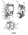
- Figures 6(a) and 6(b) are schematic views for illustrating a driving force transmitting mechanism.
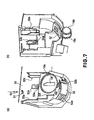
- Figures 7(a) and 7(b) are explanatory views of a toner supply apparatus frame member of the image forming apparatus main assembly.
- Figures 8(a), 8(b) and 8(c) are schematic views for illustrating a mounting operation of a developer supply container.
- Figures 9(a), 9(b) and 9(c) are schematic views for illustrating a lock release mechanism of the handle.
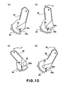
- Figures 10(a) to 10(d) are schematic views for illustrating a relationship between an amount of rotational movement.
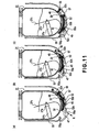
- Figures 11(a), 11(b) and 11(c) are schematic views for illustrating a shutter.
- Figure 12 is a schematic view for illustrating an amount of rotational movement and an operation of the shutter.
- the toner cartridge 31 is mounted into the image forming apparatus main assembly 100 and gradually supplies developer to a portion to be supplied with the developer while being mounted as it is, thus being of a so-called stationary type. Incidentally, the toner cartridge 31 is mounted, at a position as shown in Figure 2(b), to the image forming apparatus main assembly 100.
- the toner cartridge 31 is, as shown in Figure 3(a), provided with a handle 36 as an example of an operation member, a shutter rail 34, and a container shutter 32 slidable along the shutter rail 34.
- a toner container 31a is prepared by bonding a cover portion 31b thereto by a conventionally known means such as ultrasonic welding.
- a developer discharge opening 30 for supplying the developer is provided and a seal 48 is disposed so as to surround the developer discharge opening 30. Accordingly, when the container shutter 32 covers the developer discharge opening 30, a gap between the neighborhood of the developer discharge opening 30 and the container shutter 32 is sealed with the seal 48.
- a stirring member 37 is disposed inside the toner container 31a.
- the stirring member 37 is provided with a stirring blade 37c which is attached to a stirring shaft 37a and is rotated to function as means for feeding toner contained in the toner container 31a from the developer discharge opening.
- the stirring shaft 37a is disposed in a direction perpendicular to the insertion direction of the toner cartridge 31 and one end thereof is protruded out of the toner cartridge and provided with a stirring gear 49.
- the stirring gear 49 is engaged with a stirring drive mechanism 20 (Fig. 6(b)) provided to the apparatus main assembly when the toner cartridge 31 is mounted into the main assembly, thus transmitting a driving force.
- the stirring drive mechanism 20 is a driving force transmitting mechanism comprising a gear train, and the stirring gear 49 comes close thereto from a direction perpendicular to the rotational axis, i.e., a direction perpendicular to a facewidth direction, and is engaged with the stirring drive mechanism 20.
- a shutter lock 46 as an example of a container shutter locking portion is provided.
- the shutter lock 46 is engaged with a shutter lock receiving portion 28, so that toner is not leaked out of the toner container due to the open of the container shutter 32 even when the container shutter 32 is erroneously slidden in an open direction (indicated by an arrow X) by a user.
- the shutter lock 46 interferes with a shutter lock release projection 55f when the toner cartridge 31 is mounted into the image forming apparatus main assembly 100 ( Figure 7(a)), so that the shutter lock 46 is moved upward to release the engagement with the shutter lock receiving portion 28 as shown in Figure 4(b), thus permitting movement of the container shutter 32.
- the handle 36 is, as shown in Figures 3(a) and 4(a), axially supported at both side surfaces of the toner container 31a and can be rotationally moved in an open direction (arrow V direction) and a close direction (arrow W direction).
- a grip portion 36a of the handle 36 abuts against a container grip 35 at an upper portion of the toner container 31a, so that a rotational movement angle is restricted.
- a handle lock 38 as an example of a lock means is held by a handle lock receiving portion 33, so that the handle 36 is fixed at a predetermined angle.
- the fixed position is an initial position of the handle 36 and as shown in Figure 5(a), the handle 36 is set to be capable of being rotationally moved in both the V and W directions.
- the handle 36 is, as shown in Figure 4(a), provided with a transmitting portion 40, for transmitting a driving force for opening and closing the developer discharge opening, comprising gears.
- the driving force transmitting portion 40 is, as shown in Figure 6(a), engaged with a relay portion 19, for transmitting the driving force for opening and closing the developer discharge opening, provided to the apparatus main assembly to transmit the driving force to the driving force relay portion 19.
- the driving force relay portion 19 is a driving force transmitting mechanism comprising a gear train, and comes close to an idler gear 19a from a direction perpendicular to the rotational axis, i.e., a direction perpendicular to the face width direction, to be engaged with the idler gear 19a.
- the idler gear 19a is connected to a portion 32a, for receiving the driving force for opening and closing the developer discharge opening, provided to the container shutter 32, through a small stepped gear 19b and a large stepped gear 19c which are an example of a plurality of gears having a common rotational axis and being different in number of teeth, thus transmitting the movement of the handle 36 as an open and close motion of the container shutter 32.
- the handle 36 is provided with a handle rail 39 as an example of a container-side engaging portion as shown in Figure 3(a).
- the handle rail 39 is a stepped member shaped in an arc around the rotational movement axis of the handle 36 and is engaged with projections 53a and 54a (Fig.7) as an example of a main assembly-side engaging portion provided to the apparatus main assembly, thus fixing and holding the toner cartridge 31 with respect to the image forming apparatus main assembly.
- projections 53a and 54a are disposed at ends of base portions 53b and 54b which are integrally formed with a toner supply apparatus frame 55 as shown in Figures 7(a) and 8(a).
- Each of the projections 53a and 54a has an inclined surface as an upper surface (on an upstream side in the toner cartridge 31 insertion direction) and a surface substantially perpendicular to the insertion direction as a lower surface (on a downstream side in the insertion direction).
- an engaging boss 45 is disposed so that it protrudes from the surface of the container shutter 32.
- the apparatus shutter 52 provided to the apparatus main assembly is provided with an engaging hole 52b for being engaged with the engaging boss 45 during the mounting of the toner cartridge 31 as shown in Figure 7(a).
- the container shutter 32 and the apparatus shutter 52 cooperate in performing an open/close operation, so that three openings including a developer receiving opening 57 provided to the toner supply apparatus frame 55 of the apparatus main assembly, a toner supply opening 52a provided to the apparatus shutter 52, and the developer discharge opening 30 provided to the toner container 31a, communicate with each other. As a result, supply of the toner is performed.
- a main assembly opening seal 56 is provided, so that leakage of the toner from a gap between the developer receiving opening 57 and the apparatus shutter 52 is prevented.
- a user opens the toner cartridge cover 23 of the image forming apparatus main assembly 100 in the Y direction ( Figure 2(a)). Then, as shown in Figure 8(a), the user grips the container grip 35 at the upper portion of the toner container and starts to insert the toner cartridge 31 from above the main assembly into the toner supply apparatus frame 55 of the main assembly in a direction of an arrow R. At this time, the handle 36 is interposed between an upper handle lock receiving portion 33b and a lower handle lock receiving portion 33c of the toner container to be fixed at an initial position (Fig.5).
- the toner cartridge 31 is further inserted and when the inclined upper surfaces of the projections 53a and 54a contact the handle rail 39 of the handle 36, the base portions 53b and 54b of the projections 53a and 54a are elastically deformed. As a result, the projections 53a and 54a are moved outward in directions (indicated by arrows I and J), so that the toner cartridge 31 is inserted smoothly.
- the engaging boss 45 ( Figure 3(b)) of the container shutter 32 is engaged with the engaging hole 52b of the apparatus shutter 52.
- the container shutter 32 and the apparatus shutter 52 are placed in such a state that they can integrally cooperate to perform the open/close operation.
- the handle 36 is located at an initial position, and the handle rail 39 and the projection 54a are in such a positional relationship that they are engaged with each other at a position O.
- the handle lock 38 is not released until immediately before the toner cartridge 31 is completely inserted into the toner supply apparatus, so that this positional relationship is always kept.
- the toner supply apparatus frame 55 of the apparatus main assembly is provided with a handle lock release rib 55h for releasing lock with the handle lock 38.
- the handle lock release rib 55h abuts against the handle lock 38 during the insertion of the toner cartridge 31 as shown in Figure 3(b), so that an end of the handle lock 38 is bent toward the toner container 31a (in a direction of an arrow A1). As a result, the handle lock 38 is deviated from the handle lock receiving portion 33 to be released therefrom, so that the handle 36 is placed in a rotationally movable state.
- Figure 9(a) and 9(b) are schematic views of the handle lock 38 and the handle lock receiving portion 33 as seen in a direction from below these members
- Figure 9(c) is a schematic view of the neighborhood of the handle lock 38 as seen in the direction of the handle 36.
- Figure 9(a) shows a state that the handle 36 is locked.
- Figure 9(b) when the handle lock release rib 55h abuts against the handle lock 38 by the insertion of the toner cartridge 31, the end of the handle lock 38 is deformed toward a direction of an arrow A1 and is capable of entering a spacing between the toner container 31a and receiving portions 33b and 33c.
- the handle lock 38 located at a portion 38-0 at the time of the handle release is moved to a position 38-1 close to the toner container 31a, thus permitting rotation of the handle 36.
- a shutter lock 46 of the container shutter 32 is raised by a shutter lock release projection 55 (Fig 7(a)) in an upward direction (indicated by an arrow S shown in Figure 4(b)), so that the container shutter 32 is placed in an openable and closable state.
- the raising direction of the shutter lock 46 is approximately parallel to a direction toward a rotation center of the container shutter 32, and a rotational resistance by the contact with the seal 48 under pressure is generated, so that the container shutter 32 is not accidentally moved by the release of the shutter lock 46.
- a lock release rib 47 ( Figure 4(b)) provided to the container shutter 32 presses down on a lock 55a of the apparatus shutter 55 to release the lock 55a, thus placing also the apparatus shutter 55 in the openable and closable state.
- the driving force is transmitted from the driving force transmitting portion 40 through the driving force relay portion 19, so that the container shutter 32 and the apparatus shutter 52 start to rotationally move as shown in Figure 11(b).
- the handle rail 39 is arc-shaped and the projections 53a and 54a are disposed on a center line of rotational movement of the handle 36, so that the projections 53a and 54a continue holding the handle rail 39 at a position P ( Figure 10(b)).
- Lower ends of the projections 53a and 54a are formed in a bend shape, so that they can reduce a contact surface with the handle rail, thus decreasing a resistance during the rotation of the handle.
- a toner sensor at the buffer portion detects no toner and a cartridge replacement message is displayed. The user opens the cartridge cover 23 and performs the replacement of the toner cartridge 31.
- the user rotates the grip portion 36a in a direction of an arrow W in order to close the container shutter 32 of the toner cartridge 31 and the apparatus shutter 52.
- the projection 54a reaches a position R corresponding to a terminated portion 39a at which the handle rail 39 is terminated.
- the engagement of the projections 53a and 54a with the handle rail 39 is released, so that removal of the toner cartridge 31 becomes possible. Accordingly, in the case where the toner is emptied, the shutters are closed by such a simple operation that the handle 36 is only rotated to place the toner cartridge 31 in a removal state.
- an uppermost bar line represents whether the toner cartridge 31 is removable or unremoved
- a second bar line represents the amount of handle rotational movement during the open of the shutters.
- Symbols O, P and Q correspond to those representing the positional relationships between the handle 36 and the projection 54a shown in Figures 10(a), 10(b) and 10(c).
- the handle 36 is rotationally moved by B.
- a third bar line represents the amount of handle rotational movement during the close of the shutters.
- the driving force is not transmitted in an amount corresponding to backlash of the gear when the handle 36 starts to be moved, so the gear when the handle 36 starts to be moved, so that only the handle 36 is moved in an amount C.
- the handle 36 is rotated in the amount B but the toner cartridge 31 cannot be removed since the projection 54a is engaged with the handle rail 39.
- the terminated portion 39a comes immediately under the projection 54a, so that it is possible to remove the toner cartridge 31.
- the amount of handle rotational movement (Q to R) in the shutter close direction is larger than the amount of handle rotational movement in the shutter open direction (O to Q).
- a length of the handle rail corresponding to the amount (O to R) so that it is not less than that corresponding to backlash loss, it is possible to realize such a state that the toner cartridge 31 can be removed only after the container shutter 32 and the apparatus shutter 52 are returned to their original positions.
- the handle lock receiving portion 33 at the upper surface of the upper receiving portion 33b of the handle lock receiving portion 33 is provided with an inclined surface, so that the handle lock 38 is naturally deformed along the inclined surface to enter a spacing 33a during the closing of the handle 36.
- the spacing 33a is also provided between the lower receiving portion 33c and the toner container 31a, so that the handle 36 can be further rotated when compared with the case of the initial position.
- the handle 36 is, after the projections 53a and 54a reach the terminated portion 39a, stopped at such a further moved position at which an upper surface of the container grip 35 and a lower surface of the grip portion 36a run against each other.
- the main assembly shutter lock 55a is elastically restored to the original position to lock the apparatus shutter 52.
- the shutter lock 46 is not supplied with a pressing force from the shutter lock release projection 55f on the toner cartridge 31 side, so that the shutter lock 46 is elastically restored to the original position to be engaged with the shutter lock receiving portion 28.
- the container shutter 32 it is possible to prevent the container shutter 32 from being accidentally opened, so that there is no worry that the toner in the container is scattered out, and handling of the toner cartridge outside the main assembly becomes easy.
- an abutting portion 41 as an example of a container-side return means is provided ( Figure 4(a)).
- a return abutting portion 55c as an example of a main assembly-side return means is provided on the main assembly side as shown in Figure 7(a). The abutting portion 41 abuts against the return abutting portion 55c when the toner cartridge 31 is taken out of the main assembly, so that the handle 36 is rotationally moved to restore its phase to the initial position.
- Figures 13(a) and 13(b) are schematic views for illustrating a gear return means
- Figures 14(a) to 14(c) are schematic views for illustrating an operation of the gear return means
- Figures 15(a) to 15(c) are schematic views for illustrating an operation of a gear-side abutting portion and a container-side abutting portion.
- the rotational axis (shaft) 19d for axially supporting the small and large stepped gears 19b and 19c of the driving force relay portion 19 is provided with two opposite flat portions 19e.
- the apparatus main assembly is provided with a holding member 60 comprising a plate spring which has the same flat surface as the flat portions 19e and is urged against the flat portions 19e.
- the flat surface of the holding member 60 is set to have a width narrower than that of the flat portions 19e and the holding member 60 is disposed so as to sandwich the flat portions 19e.
- Figures 14(a) to 14(c) show a phase of the rotational axis 19d and a state of the holding member 60, wherein Figure 14(a) shows the phase when the driving force relay portion 19 is located at the initial position, Figure 14(b) shows the phase when the toner cartridge is removed from the main assembly, and Figure 14(c) shows the phase in such a state that the shutter member is opened.
- the idler gear 19a of the driving force relay portion 19 is provided with a rib-shaped gear-side abutting portion 19f
- the toner container 31a of the toner cartridge 31 is provided with a projection-shaped container-side abutting portion 29.
- the gear-side abutting portion 19f is disposed at a position at which it is at least eccentrically disposed with respect to the rotational axis of the idler gear 19a.
- the rotation by the gear-side abutting portion 19f and the container-side abutting portion 29 is held at an accurate phase by the above described gear return means when the driving force relay 19 is rotated in the correctable range, so that it is not necessary to strictly control an angle after the rotation.
- the handle 36 side it is necessary to ensure that the handle 36 is in the initial position with reliability.
- the initial position of the handle 36 is determined by holding the handle lock 38 in the handle lock receiving portion 33. However, it should prevent a deviation in phase with reliability in a period from release of the handle lock 38 to engagement of the driving force transmitting portion 40 with the idler gear 19a during the mounting of the toner cartridge 31 into the main assembly.
- a portion 50 to be guided is provided, and as shown in Figure 7(a), a guide portion 51 is provided at a side surface of the toner supply apparatus frame 55 on the apparatus main assembly side.
- the guide portion 51 is located at a position at which the handle 36 starts to guide the portion 50 to be guided in such a state (initial position) that the handle 36 is held by the handle lock 38, so that the rotational movement of the handle 36 is prevented by wall surfaces at both sides thereof in the insertion direction.
- the handle lock 38 is released, the release rib of the main assembly is pressed against the handle lock 38, so that a rotational force is generated in the handle 36.
- the rotation of the handle 36 can be prevented with reliability by the above-described constitution.
- the guide portion 51 is constituted so as not to block the rotational movement of the handle 36 by setting its position so that the position does not abut the portion 50 to be guided in such a state that the toner cartridge 31 is completed mounted.
- the driving force transmitting portion 40 of the handle 36 and the idler gear 19a of the driving force relay portion 19 can be engaged with each other always at the same phase (addendum).
- the container shutter 32 is held at the initial position by the shutter lock 46, so that the driving force transmission receiving portion 32a of the container shutter 32 and the large stepped gear 19c can be engaged with each other always at the same phase.
- the apparatus shutter 52 is engaged with the engaging boss 45 of the container shutter 32 held at the initial position through the engaging hole 52b, thus being located at its initial position.
- the positional relationship among the handle 36, the container shutter 32, and the apparatus shutter 52 can be kept constant, so that the shutter members can be rotationally moved at a predetermined angle within a rotatable range of the handle 36.
- the toner cartridge 31 is not accidentally removed from the main assembly in such a state that the apparatus shutter 52 is not sufficiently closed by the restricted rotational movement of the handle 36 and remains open.
- the apparatus shutter 52 is always kept at the initial position, so that it is possible to prevent accumulation of deviation of the apparatus shutter 52.
- a developer supply container capable of supplying powdery developer to an electrophotographic image forming apparatus for forming an image with developer and capable of being utilized in the image forming apparatus.
Landscapes
- Physics & Mathematics (AREA)
- General Physics & Mathematics (AREA)
- Dry Development In Electrophotography (AREA)
- Electrophotography Configuration And Component (AREA)
Claims (12)
- Récipient (31) d'alimentation en développateur pouvant amener un développateur à une partie, devant être alimenté en développateur d'un ensemble principal (100) d'un appareil de formation d'images en étant monté dans l'ensemble principal (100) de l'appareil de formation d'images pour permettre la transmission d'une force d'entraînement entre ledit récipient (31) d'alimentation en développateur et l'ensemble principal (100) de l'appareil de formation d'images, ledit récipient (31) d'alimentation en développateur comportant :une ouverture (30) de déchargement de développateur destinée à être disposée en opposition à und ouverture (57) de réception de développateur prévue sur l'ensemble principal (100) de l'appareil de formation d'images lorsque ledit récipient (31) d'alimentation en développateur est monté dans l'ensemble principal (100) de l'appareil de formation d'imgaes, l'ensemble principal (100) de l'appareil de formation d'images étant pourvu d'un élément obturateur (52) de l'ensemble principal pour découvrir et fermer ladite ouverture de réception de développateur ;un élément obturateur (32) du récipient destiné à découvrir et fermer ladite ouverture (30) de décharge du développateur ;un élément de manoeuvre (36) capable d'exécuter une opération de déplacement dans un état monté dudit récpient (31) d'alimentation en développateur, ladite opération de déplacement amenant une force d'entraînement à ouvrir et fermer ledit élément obturateur (52) de l'ensemble principal ;une première partie d'engrenage (40), située sur ledit élément de manoeuvre (36) pour transmettre une force d'entraînement à un train d'engrenage relai (19) situé sur l'ensemble principal (100) de l'appareil de formation d'images ; ledit train d'engrenage relai (19) comportant au moins plusieurs roues dentées (19b, 19c) ayant des nombres de dents différents situées sur un axe commun (19d) de rotation, et ladite première partie d'engrenage (40) et ledit train d'engrenage relai (19) étant mis en prise l'un avec l'autre par le montage dudit récipient (31) d'alimentation en développateur sur l'ensemble principal (100) de l'appareil de formation d'images ;une seconde partie d'engrenage (32a), située sur ledit élément obturateur (32) du récipient, destinée à être amenée en prise avec ledit train d'engrenage relai (19) par le montage dudit récipient (31) d'alimentation en développateur sur l'ensemble principal (100) de l'appareil de formation d'images pour recevoir ainsi ladite force d'entraînement dudit train d'engrenage relai (19) ; etune partie de transmission (45), située sur ledit élément obturateur (32) du récipient, destinée à être amenée en accouplement avec ledit élément obturateur (52) de l'ensemble principal par le montage dudit récipient (31) d'alimentation en développateur sur l'ensemble principal (100) de l'appareil de formation d'images pour transmettre ainsi ladite force d'entraînement reçue par ladite seconde partie d'engrenage (32a) audit élément obturateur (52) de l'ensemble principal,
caractérisé parune partie d'appui (29) du côté du récipient, destinée à venir en appui contre une partie d'appui (19f) du côté de l'engrenage située sur l'une des roues dentées (19c) du train d'engrenage relai (19);
dans lequel ladite partie d'appui (29) du côté du récipient vient en appui contre la partie d'appui (19f) du côté de l'engrenage pour faire tourner le train d'engrenage relai (19) lorsque ledit récipient (31) d'alimentation en développateur est monté dans l'ensemble principal (100) de l'appareil de formation d'images. - Récipient (31) selon la revendication 1, dans lequel ladite partie d'appui du côté du récipient vient en appui contre ladite partie d'appui du côté de l'engrenage pour faire tourner des roues dentées respectives du train d'engrenage relai (19) vers leurs positions initiales lorsque ledit récipient (31) d'alimentation en développateur est monté dans l'ensemble principal (100) de l'appareil de formation d'images.
- Récipient (31) selon la revendication 1, lequel récipient (31) d'alimentation en développateur comporte en outre une partie de verrouillage (38) destinée à verrouiller ledit élément de manoeuvre (36), et un état verrouillé est libéré par le montage dudit récipient (31) d'alimentation en développateur dans l'ensemble principal (100) de l'appareil de formation d'images.
- Récipient (31) selon la revendication 3, dans lequel ledit élément de manoeuvre (36) est pourvu d'une partie (50) destinée à être guidée par une partie de guidage (51) située sur l'ensemble principal (100) de l'appareil de formation d'images, et la partie (50) devant être guidée est guidée par la partie de guidage (51) dans un état dans lequel le verrouillage par ladite partie de verrouillage (38) est libéré.
- Récipient (31) selon la revendication 4, dans lequel la partie (50) devant être guidée commence à être guidée avant que l'état verrouillé par ladite partie de verrouillage (38) soit libéré, et est libérée de la partie de guidage (51) avant qu'une liaison de ladite première partie d'engrenage (40) avec le train d'engrenage relai (19) soit achevée.
- Récipient (31) selon la revendication 1, lequel récipient (31) d'alimentation en développateur est monté dans l'ensemble principal (100) de l'appareil de formation d'images dans une direction perpendiculaire à l'axe de rotation (19d) du train d'engrenage relai (19).
- Appareil de formation d'images sur lequel un récipient (31) d'alimentation en développateur peut être monté de façon amovible, lequel est capable de fournir un développateur à une partie devant être alimentée en développateur d'un ensemble principal (100) dudit appareil de formation d'images en réalisant la transmission d'une force d'entraînement entre un récipient (31) d'alimentation en développateur monté et l'ensemble principal (100) dudit appareil de formation d'images, ledit appareil de formation d'images comportant ;une ouverture (57) de réception de développateur destinée à être disposée en opposition à une ouverture (30) de décharge de développateur du récipient (31) d'alimentation en développateur monté, ledit récipient (31) d'alimentation en développateur étant pourvu d'un élément obturateur (32) de récipient pour découvrir et fermer ladite ouverture (30) de décharge de développateur ;un train d'engrenage relai (19) destiné à transmettre une force d'entraînement reçue d'une première partie d'engrenage (40), située sur un élément de manoeuvre (36) situé sur ledit récipient (31) d'alimentation en développateur, à une seconde partie d'engrenage (32a) située sur ledit élément obturateur (32) du récipient ; ledit train d'engrenage relai comportant au moins plusieurs roues dentées (19b, 19c) qui ont un axe de rotation commun (19d) et ont des nombres de dents différents, et ledit train d'engrenage relai (19) étant amené en prise avec ladite première partie d'engrenage (40) et ladite seconde partie d'engrenage (32a) par le montage dudit récipient (31) d'alimentation en développateur sur l'ensemble principal (100) de l'appareil de formation d'images et pouvant ouvrir et fermer ledit élément obturateur (32) du récipient en déplaçant ledit élément de manoeuvre (36) ; un élément obturateur (52) de l'appareil destiné à découvrir et fermer ladite ouverture (57) de réception de développateur ; etune partie (52b) de réception de force d'entraînement, prévue pour ledit élément obturateur (52) de l'appareil, destinée à être amenée en engagement avec ledit élément obturateur (32) du récipient par le montage dudit récipient (31) d'alimentation en développateur sur l'ensemble principal (100) de l'appareil de fomation d'images afin de recevoir ainsi ladite force d'entraînement ; ladite partie (52b) de réception de force d'entraînement recevant ladite force d'entraînement pour ouvrir et fermer ensemble ledit élément obturateur (52) de l'appareil et ledit élément obturateur (32) du récipient,
caractérisé en ce quel'une des roues dentées dudit train d'engrenage relai (19) est pourvue d'une partie d'appui (19f) du côté d'engrenage destinée à venir en appui contre une partie d'appui (29) du côté du récipient située sur le récipient (31) d'alimentation en développateur lorsque le récipient (31) d'alimentation en développateur est monté dans l'ensemble principal de l'appareil de formation d'images ;
etdans lequel la partie d'appui (29) du côté du récipient vient en appui contre la partie d'appui (19f) du côté de l'engrenage pour faire tourner le train d'engrenage relai (19) lorsque le récipient (31) d'alimentation en développateur est monté dans l'ensemble principal (100) de l'appareil de formation d'images. - Appareil selon la revendication 7, dans lequel la partie d'appui (29) du côté du récipient vient en appui contre la partie d'appui (19f) du côté de l'engrenage pour faire tourner des roues denteés respectives du train d'engrenage relai (19) vers leurs positions initiales lorsque le récipient (31) d'alimentation en développateur est monté dans l'ensemble principal (100) de l'appareil de formation d'images.
- Appareil selon la revendication 7, dans lequel le récipient (31) d'alimentation en développateur comporte en outre une partie de verrouillage (38) destinée à verrouiller l'élément de manoeuvre (36), et ledit appareil de formation d'images comporte en outre une partie (55h) de libération de verrouillage destinée à libérer un état verrouillé de la partie de verrouillage (38) lorsque le récipient (31) d'alimentation en développateur est monté dans l'ensemble principal (100) de l'appareil de formation d'images.
- Appareil selon la revendication 9, lequel appareil de formation d'images comporte en outre une partie de guidage (51) destinée à guider une partie (50) devant être guidée, prévue pour l'élément de manoeuvre (36), et ladite partie de guidage (51) guide la partie (50) devant être guidée dans un état dans lequel le verrouillage de la partie de verrouillage (38) est libéré.
- Appareil selon la revendication 10, dans lequel la partie (50) devant être guidée commence à être guidée avant que l'état verrouillé par la partie de verrouillage (38) soit libéré, et est libérée de la partie de guidage (51) avant qu'une liaison de la première partie d'engrenage (40) avec le train d'engrenage relai (19) soit complètement réalisée.
- Appareil selon la revendication 7, dans lequel le récipient (31) d'alimentation en développateur est monté dans l'ensemble principal (100) de l'appareil de formation d'images dans une direction perpendiculaire à l'axe de rotation (19d) du train d'engrenage relai (19).
Priority Applications (1)
| Application Number | Priority Date | Filing Date | Title |
|---|---|---|---|
| EP07100972A EP1780606B1 (fr) | 2004-11-12 | 2005-11-10 | Appareil de formation d'image avec un récipient d'approvisionnement en révélateur |
Applications Claiming Priority (1)
| Application Number | Priority Date | Filing Date | Title |
|---|---|---|---|
| JP2004328681A JP4636853B2 (ja) | 2004-11-12 | 2004-11-12 | 現像剤供給容器および画像形成装置 |
Related Child Applications (1)
| Application Number | Title | Priority Date | Filing Date |
|---|---|---|---|
| EP07100972A Division EP1780606B1 (fr) | 2004-11-12 | 2005-11-10 | Appareil de formation d'image avec un récipient d'approvisionnement en révélateur |
Publications (3)
| Publication Number | Publication Date |
|---|---|
| EP1684130A2 EP1684130A2 (fr) | 2006-07-26 |
| EP1684130A3 EP1684130A3 (fr) | 2006-08-23 |
| EP1684130B1 true EP1684130B1 (fr) | 2007-11-21 |
Family
ID=36386441
Family Applications (2)
| Application Number | Title | Priority Date | Filing Date |
|---|---|---|---|
| EP05024603A Expired - Lifetime EP1684130B1 (fr) | 2004-11-12 | 2005-11-10 | Récipient d`approvisionnement en révélateur et appareil de formation d`image |
| EP07100972A Expired - Lifetime EP1780606B1 (fr) | 2004-11-12 | 2005-11-10 | Appareil de formation d'image avec un récipient d'approvisionnement en révélateur |
Family Applications After (1)
| Application Number | Title | Priority Date | Filing Date |
|---|---|---|---|
| EP07100972A Expired - Lifetime EP1780606B1 (fr) | 2004-11-12 | 2005-11-10 | Appareil de formation d'image avec un récipient d'approvisionnement en révélateur |
Country Status (6)
| Country | Link |
|---|---|
| US (2) | US7369798B2 (fr) |
| EP (2) | EP1684130B1 (fr) |
| JP (1) | JP4636853B2 (fr) |
| KR (1) | KR100668536B1 (fr) |
| CN (1) | CN100472352C (fr) |
| DE (2) | DE602005008612D1 (fr) |
Families Citing this family (52)
| Publication number | Priority date | Publication date | Assignee | Title |
|---|---|---|---|---|
| JP4579655B2 (ja) * | 2004-11-12 | 2010-11-10 | キヤノン株式会社 | トナーカートリッジおよび画像形成装置 |
| RU2407049C2 (ru) | 2004-11-24 | 2010-12-20 | Кэнон Кабусики Кайся | Контейнер подачи проявителя |
| JP2006323082A (ja) * | 2005-05-18 | 2006-11-30 | Canon Inc | 現像剤補給容器 |
| ATE483183T1 (de) | 2006-07-25 | 2010-10-15 | Brother Ind Ltd | Entwicklungsmittelkartusche und bilderzeugungsvorrichtung damit |
| EP1927897B1 (fr) | 2006-09-22 | 2010-11-03 | Brother Kogyo Kabushiki Kaisha | Appareil de formation d'images et cartouche d'agent de développement |
| JP4413912B2 (ja) | 2006-11-29 | 2010-02-10 | 株式会社沖データ | 粉体カートリッジ、現像装置、及び画像形成装置 |
| JP5067865B2 (ja) * | 2007-02-21 | 2012-11-07 | キヤノン株式会社 | 現像剤補給容器及び画像形成装置 |
| JP4984970B2 (ja) * | 2007-03-01 | 2012-07-25 | ブラザー工業株式会社 | 画像形成装置 |
| JP4415037B2 (ja) * | 2007-08-22 | 2010-02-17 | 株式会社沖データ | 現像剤カートリッジ、画像形成ユニット、及び画像形成装置 |
| EP2045668B1 (fr) * | 2007-10-02 | 2014-11-12 | Brother Kogyo Kabushiki Kaisha | Unité de révélateur et dispositif de développement |
| US8200126B2 (en) * | 2007-11-30 | 2012-06-12 | Lexmark International, Inc. | Toner cartridges for an image forming device |
| JP5332336B2 (ja) * | 2008-06-20 | 2013-11-06 | 株式会社リコー | トナー補給装置及び画像形成装置 |
| JP2010054638A (ja) * | 2008-08-27 | 2010-03-11 | Sharp Corp | トナー搬送ユニットおよびこれを備える画像形成装置 |
| JP4433095B1 (ja) * | 2009-07-22 | 2010-03-17 | 富士ゼロックス株式会社 | 像形成剤収容容器、画像形成装置、像形成剤収容容器の装着方法、像形成剤収容容器の取り外し方法、像形成剤の充填方法、及び像形成剤の再充填方法。 |
| JP5692639B2 (ja) * | 2010-03-10 | 2015-04-01 | 株式会社リコー | トナー容器及び画像形成装置 |
| JP5772004B2 (ja) * | 2010-03-10 | 2015-09-02 | 株式会社リコー | トナー容器及び画像形成装置 |
| NZ601975A (en) | 2010-03-10 | 2013-06-28 | Ricoh Co Ltd | Toner container with an identifying non compatible shape part |
| USD659751S1 (en) * | 2010-03-17 | 2012-05-15 | Fuji Xerox Co., Ltd. | Toner cartridge |
| USD659752S1 (en) * | 2010-03-17 | 2012-05-15 | Fuji Xerox Co., Ltd. | Toner cartridge |
| USD659186S1 (en) * | 2010-03-17 | 2012-05-08 | Fuji Xerox Co., Ltd. | Toner cartridge |
| USD661344S1 (en) * | 2010-03-17 | 2012-06-05 | Fuji Xerox Co., Ltd. | Toner cartridge |
| JP5621360B2 (ja) * | 2010-07-01 | 2014-11-12 | 富士ゼロックス株式会社 | 現像剤収容容器及びこれを用いた画像形成装置 |
| JP5182342B2 (ja) * | 2010-09-07 | 2013-04-17 | ブラザー工業株式会社 | 現像装置 |
| JP5017475B1 (ja) * | 2011-04-15 | 2012-09-05 | 京セラドキュメントソリューションズ株式会社 | 画像形成装置およびトナーコンテナ |
| JP6083954B2 (ja) | 2011-06-06 | 2017-02-22 | キヤノン株式会社 | 現像剤補給容器及び現像剤補給システム |
| JP5273263B2 (ja) * | 2011-07-27 | 2013-08-28 | 株式会社リコー | 現像剤収容器、現像装置、プロセスユニット及び画像形成装置 |
| EP2659314B1 (fr) | 2011-07-27 | 2015-03-25 | Ricoh Company, Ltd. | Récipient de révélateur, dispositif de développement, unité de traitement et appareil de formation d'image |
| JP5212758B1 (ja) * | 2012-02-01 | 2013-06-19 | 株式会社リコー | 現像剤収容器、現像装置、プロセスユニット及び画像形成装置 |
| CN202267824U (zh) * | 2011-09-30 | 2012-06-06 | 珠海天威飞马打印耗材有限公司 | 碳粉盒 |
| JP5377686B2 (ja) * | 2012-01-31 | 2013-12-25 | 京セラドキュメントソリューションズ株式会社 | 画像形成装置及びトナー容器 |
| JP5873048B2 (ja) | 2013-07-12 | 2016-03-01 | 京セラドキュメントソリューションズ株式会社 | トナー容器及びそれを備えた画像形成装置 |
| JP5945524B2 (ja) * | 2013-09-24 | 2016-07-05 | 京セラドキュメントソリューションズ株式会社 | トナー容器を備えた画像形成装置 |
| JP6050734B2 (ja) * | 2013-09-24 | 2016-12-21 | 京セラドキュメントソリューションズ株式会社 | 画像形成装置 |
| JP6053705B2 (ja) * | 2014-02-12 | 2016-12-27 | 京セラドキュメントソリューションズ株式会社 | 画像形成装置 |
| JP6548503B2 (ja) | 2014-08-01 | 2019-07-24 | キヤノン株式会社 | トナーカートリッジ、トナー供給機構 |
| KR20160143391A (ko) * | 2015-06-05 | 2016-12-14 | 에스프린팅솔루션 주식회사 | 현상제 카트리지 및 이를 채용한 전자사진방식 화상형성장치 |
| JP6139715B2 (ja) * | 2016-01-11 | 2017-05-31 | 京セラドキュメントソリューションズ株式会社 | トナー容器及びそれを備えた画像形成装置 |
| JP6069542B2 (ja) * | 2016-01-11 | 2017-02-01 | 京セラドキュメントソリューションズ株式会社 | トナー容器及びそれを備えた画像形成装置 |
| JP6206530B2 (ja) | 2016-03-31 | 2017-10-04 | ブラザー工業株式会社 | トナーカートリッジ |
| BR112018074598B1 (pt) | 2016-06-14 | 2024-01-16 | Canon Kabushiki Kaisha | Cartucho de processo e aparelho de formação de imagem eletrofotográfica |
| JP6834251B2 (ja) * | 2016-08-26 | 2021-02-24 | ブラザー工業株式会社 | 現像装置 |
| WO2018062571A1 (fr) | 2016-09-30 | 2018-04-05 | キヤノン株式会社 | Cartouche d'encre et mécanisme d'alimentation en encre |
| JP7039226B2 (ja) | 2017-09-21 | 2022-03-22 | キヤノン株式会社 | 現像剤補給容器及び現像剤補給システム |
| JP7178000B2 (ja) * | 2018-03-13 | 2022-11-25 | 株式会社リコー | 粉体収納容器、プロセスカートリッジ、及び、画像形成装置 |
| US10866537B2 (en) | 2018-03-13 | 2020-12-15 | Ricoh Company, Ltd. | Powder container having contact portion to contact a restriction member |
| KR20200025338A (ko) * | 2018-08-30 | 2020-03-10 | 휴렛-팩커드 디벨롭먼트 컴퍼니, 엘.피. | 토너 카트리지의 회전 위상에 따라서 토너 충전부의 유입 셔터를 선택적으로 로킹하는 구조 |
| KR20200025336A (ko) * | 2018-08-30 | 2020-03-10 | 휴렛-팩커드 디벨롭먼트 컴퍼니, 엘.피. | 토너 충전부의 유입 셔터를 선택적으로 로킹하는 구조 |
| JP1638542S (fr) * | 2018-09-13 | 2019-08-05 | ||
| JP1638083S (fr) * | 2018-09-13 | 2019-08-05 | ||
| USD952030S1 (en) * | 2019-10-23 | 2022-05-17 | Lexmark International, Inc. | Toner cartridge |
| JP7362421B2 (ja) * | 2019-10-25 | 2023-10-17 | キヤノン株式会社 | 画像形成装置 |
| JP2024117511A (ja) * | 2023-02-17 | 2024-08-29 | 沖電気工業株式会社 | 画像形成ユニット及び画像形成装置 |
Family Cites Families (20)
| Publication number | Priority date | Publication date | Assignee | Title |
|---|---|---|---|---|
| US739347A (en) * | 1903-03-12 | 1903-09-22 | Samuel W Rowell | Vehicle. |
| JP3187522B2 (ja) * | 1992-04-30 | 2001-07-11 | 株式会社リコー | 回転型現像装置を用いた画像形成装置 |
| JPH05341584A (ja) * | 1992-06-09 | 1993-12-24 | Konica Corp | 画像形成装置 |
| JPH07168435A (ja) * | 1993-10-04 | 1995-07-04 | Seiko Epson Corp | トナー補給装置 |
| JP3495914B2 (ja) * | 1998-06-24 | 2004-02-09 | キヤノン株式会社 | トナー補給容器及びトナー補給装置ならびにこれらを用いたトナー補給方法 |
| JP3450757B2 (ja) * | 1998-09-22 | 2003-09-29 | キヤノン株式会社 | トナー補給容器 |
| CA2300651C (fr) * | 1999-03-17 | 2002-12-10 | Canon Kabushiki Kaisha | Contenant a toner et mecanisme de remplissage de toner |
| JP3450741B2 (ja) * | 1999-03-29 | 2003-09-29 | キヤノン株式会社 | トナー補給容器 |
| JP3445202B2 (ja) * | 1999-03-29 | 2003-09-08 | キヤノン株式会社 | トナー補給容器 |
| JP3789067B2 (ja) * | 2000-01-19 | 2006-06-21 | キヤノン株式会社 | トナー補給容器及び電子写真画像形成装置 |
| US20020020898A1 (en) * | 2000-08-16 | 2002-02-21 | Vu Quat T. | Microelectronic substrates with integrated devices |
| KR100425896B1 (ko) * | 2000-09-04 | 2004-04-03 | 캐논 가부시끼가이샤 | 화상 형성 장치를 위한 현상제 공급 용기 및 화상 형성 유닛 |
| JP3907408B2 (ja) | 2000-12-28 | 2007-04-18 | キヤノン株式会社 | 画像形成装置 |
| EP1233311B1 (fr) | 2001-02-19 | 2012-08-29 | Canon Kabushiki Kaisha | Récipient d'alimentation en toner |
| JP4422956B2 (ja) * | 2002-10-16 | 2010-03-03 | キヤノン株式会社 | 現像剤補給機構 |
| JP4320168B2 (ja) * | 2002-12-24 | 2009-08-26 | 京セラミタ株式会社 | トナー補給容器 |
| JP4208645B2 (ja) | 2003-06-03 | 2009-01-14 | キヤノン株式会社 | 現像剤補給容器 |
| JP4693393B2 (ja) * | 2003-11-19 | 2011-06-01 | キヤノン株式会社 | 現像剤補給装置 |
| JP4006426B2 (ja) * | 2004-09-08 | 2007-11-14 | キヤノン株式会社 | 現像剤補給装置及び画像形成装置 |
| JP4579655B2 (ja) | 2004-11-12 | 2010-11-10 | キヤノン株式会社 | トナーカートリッジおよび画像形成装置 |
-
2004
- 2004-11-12 JP JP2004328681A patent/JP4636853B2/ja not_active Expired - Fee Related
-
2005
- 2005-11-10 DE DE602005008612T patent/DE602005008612D1/de not_active Expired - Lifetime
- 2005-11-10 DE DE602005003439T patent/DE602005003439T2/de not_active Expired - Lifetime
- 2005-11-10 US US11/270,601 patent/US7369798B2/en not_active Expired - Fee Related
- 2005-11-10 EP EP05024603A patent/EP1684130B1/fr not_active Expired - Lifetime
- 2005-11-10 EP EP07100972A patent/EP1780606B1/fr not_active Expired - Lifetime
- 2005-11-11 CN CNB2005101194170A patent/CN100472352C/zh not_active Expired - Fee Related
- 2005-11-11 KR KR1020050107894A patent/KR100668536B1/ko not_active Expired - Fee Related
-
2008
- 2008-03-19 US US12/051,143 patent/US7539445B2/en not_active Expired - Fee Related
Also Published As
| Publication number | Publication date |
|---|---|
| KR20060052617A (ko) | 2006-05-19 |
| DE602005008612D1 (de) | 2008-09-11 |
| US7369798B2 (en) | 2008-05-06 |
| CN1773388A (zh) | 2006-05-17 |
| EP1684130A3 (fr) | 2006-08-23 |
| KR100668536B1 (ko) | 2007-01-16 |
| CN100472352C (zh) | 2009-03-25 |
| DE602005003439T2 (de) | 2008-09-25 |
| US20080213004A1 (en) | 2008-09-04 |
| JP2006139070A (ja) | 2006-06-01 |
| DE602005003439D1 (de) | 2008-01-03 |
| JP4636853B2 (ja) | 2011-02-23 |
| EP1780606B1 (fr) | 2008-07-30 |
| US7539445B2 (en) | 2009-05-26 |
| EP1684130A2 (fr) | 2006-07-26 |
| US20060104673A1 (en) | 2006-05-18 |
| EP1780606A3 (fr) | 2007-05-16 |
| EP1780606A2 (fr) | 2007-05-02 |
Similar Documents
| Publication | Publication Date | Title |
|---|---|---|
| EP1684130B1 (fr) | Récipient d`approvisionnement en révélateur et appareil de formation d`image | |
| US7738817B2 (en) | Developer supply container and image forming apparatus | |
| CN102037416B (zh) | 处理盒和电子照相成像设备 | |
| EP2645177B1 (fr) | Récipient d'approvisionnement en révélateur et appareil de réception de révélateur | |
| US7813671B2 (en) | Process cartridge and electrophotographic image forming apparatus | |
| EP1170641A2 (fr) | Unité de développement, unité de traitement et appareil électrophotographique de formation d'images | |
| US20110311272A1 (en) | Process cartridge and image forming apparatus | |
| US20150037071A1 (en) | Image forming apparatus | |
| JP4459025B2 (ja) | 現像剤供給容器 | |
| JP2006235592A (ja) | トナーカートリッジ | |
| CN111352327B (zh) | 显影装置、处理盒和成像设备 | |
| JP2005031109A (ja) | 剤供給装置及び画像形成装置 | |
| JP2007041104A (ja) | 現像剤供給容器 | |
| JP6711239B2 (ja) | 画像形成装置 | |
| JP2012226007A (ja) | 画像形成装置 | |
| CN100543613C (zh) | 调色剂盒 | |
| JP2007033783A (ja) | 現像剤補給容器 | |
| JP2004333608A (ja) | 現像剤補給容器 | |
| JP2020118928A (ja) | トナー容器及び画像形成装置 |
Legal Events
| Date | Code | Title | Description |
|---|---|---|---|
| PUAI | Public reference made under article 153(3) epc to a published international application that has entered the european phase |
Free format text: ORIGINAL CODE: 0009012 |
|
| PUAL | Search report despatched |
Free format text: ORIGINAL CODE: 0009013 |
|
| 17P | Request for examination filed |
Effective date: 20051110 |
|
| AK | Designated contracting states |
Kind code of ref document: A2 Designated state(s): AT BE BG CH CY CZ DE DK EE ES FI FR GB GR HU IE IS IT LI LT LU LV MC NL PL PT RO SE SI SK TR |
|
| AX | Request for extension of the european patent |
Extension state: AL BA HR MK YU |
|
| AK | Designated contracting states |
Kind code of ref document: A3 Designated state(s): AT BE BG CH CY CZ DE DK EE ES FI FR GB GR HU IE IS IT LI LT LU LV MC NL PL PT RO SE SI SK TR |
|
| AX | Request for extension of the european patent |
Extension state: AL BA HR MK YU |
|
| GRAP | Despatch of communication of intention to grant a patent |
Free format text: ORIGINAL CODE: EPIDOSNIGR1 |
|
| AKX | Designation fees paid |
Designated state(s): DE FR GB IT |
|
| GRAS | Grant fee paid |
Free format text: ORIGINAL CODE: EPIDOSNIGR3 |
|
| GRAA | (expected) grant |
Free format text: ORIGINAL CODE: 0009210 |
|
| AK | Designated contracting states |
Kind code of ref document: B1 Designated state(s): DE FR GB IT |
|
| REG | Reference to a national code |
Ref country code: GB Ref legal event code: FG4D |
|
| REF | Corresponds to: |
Ref document number: 602005003439 Country of ref document: DE Date of ref document: 20080103 Kind code of ref document: P |
|
| ET | Fr: translation filed | ||
| PLBE | No opposition filed within time limit |
Free format text: ORIGINAL CODE: 0009261 |
|
| STAA | Information on the status of an ep patent application or granted ep patent |
Free format text: STATUS: NO OPPOSITION FILED WITHIN TIME LIMIT |
|
| 26N | No opposition filed |
Effective date: 20080822 |
|
| PGFP | Annual fee paid to national office [announced via postgrant information from national office to epo] |
Ref country code: DE Payment date: 20141130 Year of fee payment: 10 Ref country code: GB Payment date: 20141124 Year of fee payment: 10 |
|
| PGFP | Annual fee paid to national office [announced via postgrant information from national office to epo] |
Ref country code: FR Payment date: 20141126 Year of fee payment: 10 |
|
| PGFP | Annual fee paid to national office [announced via postgrant information from national office to epo] |
Ref country code: IT Payment date: 20141110 Year of fee payment: 10 |
|
| REG | Reference to a national code |
Ref country code: DE Ref legal event code: R119 Ref document number: 602005003439 Country of ref document: DE |
|
| GBPC | Gb: european patent ceased through non-payment of renewal fee |
Effective date: 20151110 |
|
| PG25 | Lapsed in a contracting state [announced via postgrant information from national office to epo] |
Ref country code: IT Free format text: LAPSE BECAUSE OF NON-PAYMENT OF DUE FEES Effective date: 20151110 |
|
| REG | Reference to a national code |
Ref country code: FR Ref legal event code: ST Effective date: 20160729 |
|
| PG25 | Lapsed in a contracting state [announced via postgrant information from national office to epo] |
Ref country code: DE Free format text: LAPSE BECAUSE OF NON-PAYMENT OF DUE FEES Effective date: 20160601 Ref country code: GB Free format text: LAPSE BECAUSE OF NON-PAYMENT OF DUE FEES Effective date: 20151110 |
|
| PG25 | Lapsed in a contracting state [announced via postgrant information from national office to epo] |
Ref country code: FR Free format text: LAPSE BECAUSE OF NON-PAYMENT OF DUE FEES Effective date: 20151130 |