EP1684320A2 - Umgekehrter Betätigungsmechanismus eines Hilfschalters und damit versehener Schutzschalter - Google Patents
Umgekehrter Betätigungsmechanismus eines Hilfschalters und damit versehener Schutzschalter Download PDFInfo
- Publication number
- EP1684320A2 EP1684320A2 EP06001206A EP06001206A EP1684320A2 EP 1684320 A2 EP1684320 A2 EP 1684320A2 EP 06001206 A EP06001206 A EP 06001206A EP 06001206 A EP06001206 A EP 06001206A EP 1684320 A2 EP1684320 A2 EP 1684320A2
- Authority
- EP
- European Patent Office
- Prior art keywords
- auxiliary switch
- actuating lever
- linkage assembly
- circuit breaker
- separable contacts
- Prior art date
- Legal status (The legal status is an assumption and is not a legal conclusion. Google has not performed a legal analysis and makes no representation as to the accuracy of the status listed.)
- Granted
Links
Images




Classifications
-
- H—ELECTRICITY
- H01—ELECTRIC ELEMENTS
- H01H—ELECTRIC SWITCHES; RELAYS; SELECTORS; EMERGENCY PROTECTIVE DEVICES
- H01H71/00—Details of the protective switches or relays covered by groups H01H73/00 - H01H83/00
- H01H71/10—Operating or release mechanisms
- H01H71/12—Automatic release mechanisms with or without manual release
- H01H71/46—Automatic release mechanisms with or without manual release having means for operating auxiliary contacts additional to the main contacts
- H01H71/465—Self-contained, easily replaceable microswitches
-
- H—ELECTRICITY
- H01—ELECTRIC ELEMENTS
- H01H—ELECTRIC SWITCHES; RELAYS; SELECTORS; EMERGENCY PROTECTIVE DEVICES
- H01H71/00—Details of the protective switches or relays covered by groups H01H73/00 - H01H83/00
- H01H71/10—Operating or release mechanisms
- H01H71/12—Automatic release mechanisms with or without manual release
- H01H71/46—Automatic release mechanisms with or without manual release having means for operating auxiliary contacts additional to the main contacts
- H01H2071/467—Automatic release mechanisms with or without manual release having means for operating auxiliary contacts additional to the main contacts with history indication, e.g. of trip and/or kind of trip, number of short circuits etc.
Definitions
- the present invention relates generally to electrical switching apparatus and, more particularly, to an auxiliary switch actuator mechanism for a circuit breaker.
- the invention also relates to circuit breakers employing an auxiliary switch actuator mechanism.
- Circuit breakers having auxiliary switches are generally old and well known in the art.
- the auxiliary switch is electrically connected with a circuit including a status indicator (e.g., an audible alarm, such as a bell, or a visual indicator, such as a light) for providing a remote indication of the condition of the circuit breaker.
- a status indicator e.g., an audible alarm, such as a bell, or a visual indicator, such as a light
- Some auxiliary switches provide different outputs for each of the three general circuit breaker conditions, OFF, ON, and tripped. Other auxiliary switches only provide an indication when the circuit breaker has tripped.
- auxiliary switches which will be discussed in further detail herein, is substantially uniform and unchanging throughout the industry. While this is advantageous from the standpoint of establishing an industry standard, it is disadvantageous in that there is a lack of variation in switch design making it difficult to accommodate the differing requirements of various switching applications. For example, the microswitch or internal contacts of most known auxiliary switches are not actuated unless the circuit breaker is tripped. In certain applications, it is desirable to have the opposite situation, with the microswitch being activated until the breaker trips.
- Known auxiliary switch designs alone, cannot accommodate these circumstances. Therefore, in order to achieve the desired auxiliary switch operation, it has been necessary to make modifications to the internal components of the circuit breaker. Accordingly, known circuit breaker designs have begun to incorporate auxiliary switch actuating mechanisms.
- U.S. Patent No. 4,707,674 discloses a representative auxiliary switch actuator mechanism of the type shown in Figures 1 and 2.
- Figure 1 shows a circuit breaker 2 and the auxiliary switch actuating mechanism 4 therefor.
- Figure 2 shows certain elements of the actuating mechanism 4 in greater detail.
- a breaker mechanism 8 acts on a movable contact arm 10 causing it to pivot about the pivot axis defined by mounting pin 12.
- a movable contact 14 on the contact arm 10 engages a fixed contact 16, as shown.
- the bottom surface 18 thereof engages actuator arm 20 causing actuator member 22 to pivot about the axis defined by mounting pin 24, against a spring-bias exerted by an internal contact (not shown) of auxiliary switch 26.
- the internal contact (not shown) is coupled to movable pin 28 and is actuated thereby.
- the actuator member 22 continues to move, the end of it opposite pin 24 slides past shoulder 30 of locking member 32 (see also Figure 2).
- a spring 34 biases the locking member 32 counterclockwise (with respect to Figure 1) about pin 12, which results in shoulder 30 overlapping the upper surface 36 of base plate 38 at this location, thereby forming a stop which prevents movement of actuator member 22. Additionally, finger 40 engages the back edge 42 ( Figure 2) of slot 44 ( Figure 2) in actuator member 22 thus limiting the counterclockwise motion of locking member 32. In this manner, the auxiliary switch 26 is held in the actuated position until the shoulder 30 of locking arm 46 is moved out of engagement with the actuator member 22.
- the auxiliary switch 26 has three contact terminals including a common (“C") terminal 48 proximate the line side of the circuit breaker 2, a normally closed (“NC”) terminal 50 proximate the opposite or load side of the circuit breaker 2, and a generally central normally open (“NO”) terminal 52.
- the circuit breaker 2 is turned ON ( Figure 1), the circuit through the main breaker contacts 14,16 is closed and the actuator member 22 sets the auxiliary switch 26, as previously discussed. This represents the actuated state of the auxiliary switch 26 in which the circuit between the C and NO terminals 48,52 is closed.
- the auxiliary switch 26 could be operated in the opposite manner (e.g., with the C terminal 48 being electrically connected to the NC terminal 50 when the main breaker contacts 14,16 are closed).
- a sear pin 54 engages the link members of the breaker mechanism 8 in order to prevent them from collapsing.
- the breaker mechanism 8 remains engaged and locked by the sear pin 54 as the handle 6 pivots counterclockwise (with respect to Figure 1) from the ON position ( Figure 1) toward the OFF position (not shown).
- the sear pin 54 follows a first path of travel which avoids contact with second arm 56 of locking member 32.
- movable contact arm 10 pivots upward, counterclockwise about pin 12, movable contact 14 disengages fixed contact 16 in order to open the main circuit.
- shoulder 30 disengages base plate 38, releasing the actuator member 22 and allowing movable pin 28 of the auxiliary switch 26 to move outwardly in accordance with the bias provided by internal spring contact (not shown) in order that the auxiliary switch 26 switches from the actuated state to the non-actuated state. Therefore, an alarm circuit (not shown) connected between the C and NC terminals 48,50 of the auxiliary switch 26, is closed.
- auxiliary switch actuating mechanism is complex, requires numerous separate components and demands that all of the components interact precisely in order to function properly.
- shoulder and slot features and multiple interacting components previously discussed could slip, become misaligned, or otherwise fail to interact correctly.
- auxiliary switch requires the auxiliary switch to be modified, for example, to include a molded projection ( Figures 1 and 2) with openings to receive mounting pin 24 about which actuator member 22 pivots.
- the present invention is directed to a reverse-action auxiliary switch actuating mechanism for a circuit breaker.
- the circuit breaker includes a spring-biased actuating assembly in order to normally actuate the auxiliary switch when the circuit breaker is ON or OFF.
- the spring-bias is overcome when the breaker trips resulting in operation (e.g., actuation of a status indication such as an audible alarm or visual light) which is opposite the normal operation of a standard auxiliary switch.
- the present invention through the design of an actuating mechanism for the circuit breaker, reverses the operation of the auxiliary switch.
- an auxiliary switch actuating mechanism is for an electrical switching apparatus including a housing enclosing separable contacts, an operating mechanism including an operating handle protruding from the housing and structured to open and close the separable contacts, a linkage assembly interconnecting the operating handle and the separable contacts and moving between a set position corresponding to the separable contacts not being tripped open, and a collapsed position corresponding to the separable contacts being tripped open, an actuator structured to collapse the linkage assembly in response to a trip condition, and an auxiliary switch having a contact member.
- the auxiliary switch actuating mechanism comprises: an actuating lever including a first end and a second end, the actuating lever structured to be pivotally coupled within the housing proximate the auxiliary switch; and a bias member structured to bias the actuating lever towards engaging the contact member of the auxiliary switch, wherein the first end of the actuating lever is structured to engage and actuate the contact member of the auxiliary switch in accordance with the bias when the separable contacts are not tripped open and the linkage assembly is in the set position, and wherein the second end of the actuating lever is structured to be engaged and pivoted by the linkage assembly when the separable contacts are tripped open in response to the tripping condition and the linkage assembly is in the collapsed position, in order that the actuating lever overcomes the bias and disengages and deactivates the contact member of the auxiliary switch.
- the linkage assembly may include a U-shaped link and the second end of the actuating lever may include a paddle.
- the paddle may be structured to be engaged by the U-shaped link when the separable contacts are tripped open and the linkage assembly collapses, in order to pivot the actuating lever and overcome the bias causing the second end of the actuating lever to disengage and deactivate the contact member of the auxiliary switch.
- the actuating lever may be a single-piece molded member.
- the housing may be a two-piece molded housing having a first half and a second half, the actuating lever may include a pivot portion, and the first and second halves of the molded housing may include a receptacle wherein the pivot portion is structured to pivotally engage the receptacle.
- a circuit breaker comprises: a housing; separable contacts enclosed within the housing; an operating mechanism including an operating handle for opening and closing the separable contacts, the operating handle protruding from the housing, a linkage assembly interconnecting the operating handle and the separable contacts, the linkage assembly moving between a set position corresponding to the separable contacts not being tripped open and a collapsed position corresponding to the separable contacts being tripped open, and an actuator structured to collapse the linkage assembly in response to a trip condition; an auxiliary switch having a contact member; and an auxiliary switch actuating mechanism comprising: an actuating lever including a first end and a second end, the actuating lever pivotally coupled within the housing proximate the auxiliary switch, and a bias member biasing the actuating lever towards engaging the contact member of the auxiliary switch, wherein the first end of the actuating lever engages and actuates the contact member in accordance with the bias when the separable contacts are not tripped open and
- the housing may further include a pivot securing the bias member, which may be a torsion spring, thereto.
- circuit breakers e.g ., hydraulic circuit breakers; non-hydraulic circuit breakers
- other electrical switching apparatus e.g ., without limitation, circuit switching devices and other circuit interrupters such as contactors, motor starters, motor controllers and other load controllers.
- fastener refers to any suitable connecting or tightening mechanism expressly including, but not limited to, screws, bolts and the combinations of bolts and nuts (e.g., without limitation, lock nuts) and bolts, washers and nuts.
- trip condition refers to any abnormal electrical condition causing a circuit breaker to trip and expressly includes, without limitation, an overcurrent condition, an overload condition, an arc fault condition, a ground fault condition, an undervoltage condition, or a relatively high level short circuit or fault condition.
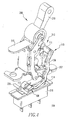
- FIG 3 shows an auxiliary switch actuating mechanism 104 for an electrical switching apparatus, such as the hydraulic-magnetic circuit breaker 202, shown.
- the circuit breaker 202 includes a housing 204.
- the housing is a two-piece molded housing 204 having first and second halves 220,222.
- the housing 204 encloses separable contacts 206 (shown in the closed position in Figure 3).
- the circuit breaker 202 further includes an operating mechanism 208, an auxiliary switch 216 and the exemplary auxiliary switch actuating mechanism 104.
- the example operating mechanism 208 is similar in configuration and function to breaker mechanism 8 illustrated and discussed previously with respect to Figures 1. and 2. Specifically, the operating mechanism 208 includes an operating handle 210 which protrudes from the housing 204 and is structured to open and close the separable contacts 206. A linkage assembly 212 interconnects the base of the operating handle 210 and the separable contacts 206. More precisely, the separable contacts 206 include a moveable contact 207 and a stationary contact 209. The stationary contact 209 is in electrical communication with a terminal 217, for example on the load side of the circuit breaker 202.
- the moveable contact 207 is mechanically interconnected with the operating handle 210 by linkage assembly 212 and is structured to move in accordance therewith between a first position in which the moveable and stationary contacts 207,209 contact one another ( Figure 3) and a second position in which they are spaced apart (not shown).
- the exemplary linkage assembly 212 includes a first link 211 and a second or U-shaped link 213 which links are structured to collapse in response to a trip condition. The details of this collapse are substantially similar to those previously discussed in connection with the link components of breaker mechanism 8 of Figures 1 and 2.
- the linkage assembly 212 In operation, when the linkage assembly 212 collapses, the U-shaped link 213 engages and pivots the exemplary auxiliary switch actuating mechanism 104, as will be discussed in further detail below. Specifically, the linkage assembly 212 moves between a set position (see, e.g., Figures 3-5) corresponding to the separable contacts 206 not being tripped open, and a collapsed position ( Figure 6) corresponding the separable contacts 206 (only moveable contact 207 is shown in Figure 6) being tripped open.
- An actuator such as a solenoid 214, initiates the collapse of the linkage assembly 212.
- the operating mechanism 208 includes an armature 215 which is actuated and moved by the solenoid 214 or other suitable actuator, in a known manner (e.g ., as was discussed above in connection with the armature 58 and sear pin 54 of Figure 1), in response to the trip condition, thereby releasing the linkage assembly 212 and allowing it to collapse.
- the auxiliary switch actuating mechanism 104 includes an actuating lever 106 having a first end 108 and a second end 110.
- the actuating lever 106 is pivotally coupled within the circuit breaker housing 204 proximate the auxiliary switch 216.
- the exemplary actuating lever 106 is a single-piece molded member including a pivot portion 114, such as the integrally formed molded pin between the first and second ends 108, 110 of the actuating lever 106 of Figures 3-6.
- the pivot portion 114 engages a receptacle 224 or molded socket ( Figure 3) in the interior of the housing 204.
- the molded pin projection pivot portion 114 is pivotally received within receptacles 224 in each of the first and second halves 220,222 of the exemplary two-piece molded housing 204 (in Figure 3, one receptacle 224 is shown in first half 220 of housing 204).
- the actuating lever 106 could alternatively be pivotally secured to the housing 204 in any known or suitable manner other than the exemplary molded pin 114 and receptacle 224 arrangement.
- a fastener (not shown) and sleeve (not shown) combination could be employed to pivotally secure the actuating lever 106 within the housing 204.
- a bias member such as the torsion spring 112 shown in Figures 3-6, biases the first end 108 of the actuating lever 106 towards engaging a contact member 218 of the auxiliary switch 216.
- the contact member 218 moves between an actuated position ( Figures 3-5) in which the circuit between the auxiliary switch NO and C contacts is closed, and a second, non-actuated position ( Figure 6) in which the contact member 218 is not depressed and the circuit between the auxiliary switch NC and C contacts is closed.
- the second end 110 of the exemplary actuating lever 106 includes a paddle 111 (best shown in Figure 4) which is engaged by the U-shaped link 213 when the separable contacts 206 are tripped open and the linkage assembly 212 collapses (Figure 6).
- the U-shaped link 213 engages the paddle 111 which causes the actuating lever 106 to pivot (clockwise with respect to Figure 6) about pivot portion 114, thereby overcoming the bias applied to the first end 108 of the actuating lever 106 by torsion spring 112.
- the contact member 218 of the auxiliary switch 216 is disengaged and deactivated, as shown in Figure 6.
- the exemplary torsion spring 112 is secured to housing 204 ( Figure 3) by a pivot 226.
- the exemplary pivot 226 is a pin which is received through the coils of the torsion spring 112 and engages a receptacle 227 on at least one half (e.g., first half 220) of the circuit breaker housing 204 ( Figure 3).
- the pivot 226 could alternatively be secured within the housing 204 by any known or suitable alternative mechanism (not shown).
- auxiliary switch actuating mechanism 104 illustrated and discussed herein is but one representative embodiment contemplated by the present invention.
- Alternative shapes, sizes and configurations of the components of the mechanism such as, for example, the actuating lever 106, could be employed.
- the actuating lever 106 has been illustrated and discussed herein as being a single-piece molded member which is substantially rigid. While the exemplary molded member is made from, for example, plastic, it could alternatively be made from any known or suitable material (e.g., without limitation, metal). Additionally, this member is not required to be molded, but could alternatively be made from a different suitable manufacturing process.
- the shape, configuration and composition of the lever 106 which is shown and discussed herein, do not limit the scope of the invention.
- the auxiliary switch actuating mechanism 104 of the present invention provides a mechanism for use with, for example, circuit breakers, in order to achieve desired auxiliary switch operating characteristics.
- the invention provides a relatively simple method of operating an auxiliary switch and associated electrical circuits in a manner reversed from its standard operation (e.g., with the auxiliary switch being actuated when the circuit breaker is not tripped and non-actuated when the circuit breaker is tripped).
- the present invention accomplishes all of the foregoing without requiring modification to the auxiliary switch and through use of a minimal number of relatively simple components.
Landscapes
- Breakers (AREA)
Applications Claiming Priority (1)
| Application Number | Priority Date | Filing Date | Title |
|---|---|---|---|
| US11/043,840 US7098416B2 (en) | 2005-01-25 | 2005-01-25 | Reverse-action auxiliary switch actuator mechanism and circuit breaker employing the same |
Publications (3)
| Publication Number | Publication Date |
|---|---|
| EP1684320A2 true EP1684320A2 (de) | 2006-07-26 |
| EP1684320A3 EP1684320A3 (de) | 2007-10-17 |
| EP1684320B1 EP1684320B1 (de) | 2011-11-23 |
Family
ID=35985145
Family Applications (1)
| Application Number | Title | Priority Date | Filing Date |
|---|---|---|---|
| EP06001206A Expired - Lifetime EP1684320B1 (de) | 2005-01-25 | 2006-01-20 | Umgekehrter Betätigungsmechanismus eines Hilfschalters und damit versehener Schutzschalter |
Country Status (5)
| Country | Link |
|---|---|
| US (1) | US7098416B2 (de) |
| EP (1) | EP1684320B1 (de) |
| AT (1) | ATE535006T1 (de) |
| CA (1) | CA2533987A1 (de) |
| MY (1) | MY137676A (de) |
Cited By (2)
| Publication number | Priority date | Publication date | Assignee | Title |
|---|---|---|---|---|
| EP2249366A1 (de) * | 2009-05-06 | 2010-11-10 | ABB Technology AG | Signalisierungsvorrichtung für einen Schutzschalter und elektrische Vorrichtung mit der Signalisierungsvorrichtung |
| CN104795260A (zh) * | 2015-04-21 | 2015-07-22 | 温州圣普电气有限公司 | 一种电能表外置断路器 |
Families Citing this family (9)
| Publication number | Priority date | Publication date | Assignee | Title |
|---|---|---|---|---|
| CN102299024B (zh) * | 2011-08-19 | 2014-02-12 | 山东卓尔电气有限公司 | 电磁式开关的锁扣装置 |
| US9281150B2 (en) * | 2012-03-12 | 2016-03-08 | Siemens Aktiengesellschaft | Circuit breaker trip blocking apparatus, systems, and methods of operation |
| CN103325629B (zh) * | 2012-03-22 | 2016-08-03 | 上海良信电器股份有限公司 | 双断点断路器的复位机构 |
| US9966209B1 (en) * | 2017-02-23 | 2018-05-08 | Carling Technologies, Inc. | Circuit breaker with arc shield |
| CN106847638A (zh) * | 2017-03-14 | 2017-06-13 | 江苏高博锐电气有限公司 | 一种外挂辅助触头 |
| JP6830404B2 (ja) * | 2017-05-26 | 2021-02-17 | 日本電産サンキョー株式会社 | スイッチ機構およびギアードモータ、ならびにダンパ装置 |
| US11059474B2 (en) | 2018-10-09 | 2021-07-13 | Ford Global Technologies, Llc | Hybrid vehicle with electrical power outlet |
| US11043801B2 (en) * | 2018-10-09 | 2021-06-22 | Ford Global Technologies, Llc | Hybrid vehicle with electrical power outlet |
| KR102039323B1 (ko) * | 2019-05-16 | 2019-11-26 | 주식회사 와이엠텍 | 마이크로스위치를 이용한 보조 접점 장치를 갖는 직류 스위치 장치 |
Family Cites Families (13)
| Publication number | Priority date | Publication date | Assignee | Title |
|---|---|---|---|---|
| US4211989A (en) * | 1978-10-02 | 1980-07-08 | General Electric Company | Circuit breaker bell alarm and lockout accessory apparatus |
| JPS6132324A (ja) * | 1984-07-20 | 1986-02-15 | 富士電機株式会社 | 配線用遮断器の内部付属装置取付構造 |
| US4707674A (en) * | 1986-01-02 | 1987-11-17 | Airpax Corporation | Auxiliary switch actuator mechanism |
| US4760226A (en) * | 1987-04-08 | 1988-07-26 | Carlingswitch, Inc. | Split case circuit breaker with multi-purpose well |
| US4864263A (en) * | 1987-09-03 | 1989-09-05 | General Electric Company | Molded case circuit breaker latch and operating mechanism assembly |
| US4831221A (en) * | 1987-12-16 | 1989-05-16 | General Electric Company | Molded case circuit breaker auxiliary switch unit |
| US5107236A (en) * | 1990-07-16 | 1992-04-21 | General Electric Company | Molded case circuit breaker trip-to-test button and auxiliary switch interface |
| US5552755A (en) * | 1992-09-11 | 1996-09-03 | Eaton Corporation | Circuit breaker with auxiliary switch actuated by cascaded actuating members |
| FR2704354B1 (fr) * | 1993-04-20 | 1995-06-23 | Merlin Gerin | Mecanisme de commande d'un disjoncteur electrique modulaire. |
| US6072136A (en) * | 1998-05-07 | 2000-06-06 | Eaton Corporation | Electrical switching apparatus with modular operating mechanism for mounting and controlling large compression close spring |
| DE19906236A1 (de) * | 1999-02-15 | 2000-08-17 | Abb Patent Gmbh | Elektrisches Installationsschaltgerät |
| FR2792768B1 (fr) * | 1999-04-22 | 2001-06-15 | Schneider Electric Ind Sa | Disjoncteur limiteur comportant un accumulateur d'energie auxiliaire |
| US6498310B1 (en) * | 2001-07-19 | 2002-12-24 | Carling Technologies, Inc. | Reverse alarm switch circuit breaker |
-
2005
- 2005-01-25 US US11/043,840 patent/US7098416B2/en not_active Expired - Lifetime
-
2006
- 2006-01-20 AT AT06001206T patent/ATE535006T1/de active
- 2006-01-20 EP EP06001206A patent/EP1684320B1/de not_active Expired - Lifetime
- 2006-01-25 CA CA002533987A patent/CA2533987A1/en not_active Abandoned
- 2006-01-25 MY MYPI20060350A patent/MY137676A/en unknown
Cited By (5)
| Publication number | Priority date | Publication date | Assignee | Title |
|---|---|---|---|---|
| EP2249366A1 (de) * | 2009-05-06 | 2010-11-10 | ABB Technology AG | Signalisierungsvorrichtung für einen Schutzschalter und elektrische Vorrichtung mit der Signalisierungsvorrichtung |
| CN101882537A (zh) * | 2009-05-06 | 2010-11-10 | Abb技术有限公司 | 用于断路器的信号装置和包括该信号装置的电气设备 |
| US8304674B2 (en) | 2009-05-06 | 2012-11-06 | Abb Technology Ag | Signaling device for circuit breaker and electrical apparatus comprising the signaling device |
| CN101882537B (zh) * | 2009-05-06 | 2014-09-10 | Abb技术有限公司 | 用于断路器的信号装置和包括该信号装置的电气设备 |
| CN104795260A (zh) * | 2015-04-21 | 2015-07-22 | 温州圣普电气有限公司 | 一种电能表外置断路器 |
Also Published As
| Publication number | Publication date |
|---|---|
| EP1684320B1 (de) | 2011-11-23 |
| EP1684320A3 (de) | 2007-10-17 |
| ATE535006T1 (de) | 2011-12-15 |
| CA2533987A1 (en) | 2006-07-25 |
| US20060163049A1 (en) | 2006-07-27 |
| MY137676A (en) | 2009-02-27 |
| US7098416B2 (en) | 2006-08-29 |
Similar Documents
| Publication | Publication Date | Title |
|---|---|---|
| EP1983542B1 (de) | Elektrische Schaltvorrichtung sowie Verriegelungsanordnung und Verriegelungseinraststeuermechanismus dafür | |
| EP2249367B1 (de) | Schutzschalter mit Hilfsschalter und deren Betätigungsmechanismen | |
| US7843291B2 (en) | Integrated maglatch accessory | |
| CA2629502A1 (en) | Electrical switching apparatus, and latch assembly and latch engagement control mechanism therefor | |
| JPH0349173B2 (de) | ||
| EP1684320B1 (de) | Umgekehrter Betätigungsmechanismus eines Hilfschalters und damit versehener Schutzschalter | |
| US6812423B1 (en) | Circuit breaker including lock for operating mechanism linkage | |
| US7911298B2 (en) | Electrical switching apparatus and trip actuator assembly therefor | |
| US5557082A (en) | Circuit breaker with common trip mechanism | |
| US6778048B1 (en) | Circuit breaker interface mechanism for bell alarm switch | |
| US8378245B2 (en) | Electrical switching apparatus, and handle assembly and push-to-trip mechanism therefor | |
| US7064635B2 (en) | Circuit breaker including alarm interface lever | |
| US6903635B2 (en) | Circuit breaker interface mechanism for auxiliary switch accessory | |
| US7154361B2 (en) | Accessories for a rotatable latching shaft of a circuit breaker | |
| US4266105A (en) | Biasing means for combination actuator | |
| US7586394B2 (en) | Electrical switching apparatus, and trip actuator reset assembly and lever arm assembly therefor | |
| US6800824B1 (en) | Circuit breaker including frame having stop for operating mechanism link | |
| US7268652B2 (en) | Cradle assembly with opening assist mechanism and electrical switching apparatus employing the same | |
| CN103247456B (zh) | 电气的开关设备尤其断路器 | |
| MXPA06001040A (es) | Mecanismo accionador de interruptor auxiliar de accion inversa y disyuntor de circuito que emplea el mismo | |
| US7106155B2 (en) | Double-lever mechanism, trip actuator assembly and electrical switching apparatus employing the same | |
| JPH0475227A (ja) | 回路遮断器 | |
| JPH0136652B2 (de) | ||
| US1360280A (en) | Circuit-breaker | |
| EP2774165B1 (de) | Elektromagnetischer trennschalter |
Legal Events
| Date | Code | Title | Description |
|---|---|---|---|
| PUAI | Public reference made under article 153(3) epc to a published international application that has entered the european phase |
Free format text: ORIGINAL CODE: 0009012 |
|
| AK | Designated contracting states |
Kind code of ref document: A2 Designated state(s): AT BE BG CH CY CZ DE DK EE ES FI FR GB GR HU IE IS IT LI LT LU LV MC NL PL PT RO SE SI SK TR |
|
| AX | Request for extension of the european patent |
Extension state: AL BA HR MK YU |
|
| PUAL | Search report despatched |
Free format text: ORIGINAL CODE: 0009013 |
|
| AK | Designated contracting states |
Kind code of ref document: A3 Designated state(s): AT BE BG CH CY CZ DE DK EE ES FI FR GB GR HU IE IS IT LI LT LU LV MC NL PL PT RO SE SI SK TR |
|
| AX | Request for extension of the european patent |
Extension state: AL BA HR MK YU |
|
| 17P | Request for examination filed |
Effective date: 20080225 |
|
| 17Q | First examination report despatched |
Effective date: 20080515 |
|
| AKX | Designation fees paid |
Designated state(s): AT BE BG CH CY CZ DE DK EE ES FI FR GB GR HU IE IS IT LI LT LU LV MC NL PL PT RO SE SI SK TR |
|
| GRAP | Despatch of communication of intention to grant a patent |
Free format text: ORIGINAL CODE: EPIDOSNIGR1 |
|
| GRAS | Grant fee paid |
Free format text: ORIGINAL CODE: EPIDOSNIGR3 |
|
| GRAA | (expected) grant |
Free format text: ORIGINAL CODE: 0009210 |
|
| AK | Designated contracting states |
Kind code of ref document: B1 Designated state(s): AT BE BG CH CY CZ DE DK EE ES FI FR GB GR HU IE IS IT LI LT LU LV MC NL PL PT RO SE SI SK TR |
|
| REG | Reference to a national code |
Ref country code: GB Ref legal event code: FG4D |
|
| REG | Reference to a national code |
Ref country code: CH Ref legal event code: EP |
|
| REG | Reference to a national code |
Ref country code: IE Ref legal event code: FG4D |
|
| REG | Reference to a national code |
Ref country code: DE Ref legal event code: R096 Ref document number: 602006025957 Country of ref document: DE Effective date: 20120119 |
|
| REG | Reference to a national code |
Ref country code: NL Ref legal event code: VDEP Effective date: 20111123 |
|
| LTIE | Lt: invalidation of european patent or patent extension |
Effective date: 20111123 |
|
| PG25 | Lapsed in a contracting state [announced via postgrant information from national office to epo] |
Ref country code: IS Free format text: LAPSE BECAUSE OF FAILURE TO SUBMIT A TRANSLATION OF THE DESCRIPTION OR TO PAY THE FEE WITHIN THE PRESCRIBED TIME-LIMIT Effective date: 20120323 Ref country code: LT Free format text: LAPSE BECAUSE OF FAILURE TO SUBMIT A TRANSLATION OF THE DESCRIPTION OR TO PAY THE FEE WITHIN THE PRESCRIBED TIME-LIMIT Effective date: 20111123 |
|
| PG25 | Lapsed in a contracting state [announced via postgrant information from national office to epo] |
Ref country code: GR Free format text: LAPSE BECAUSE OF FAILURE TO SUBMIT A TRANSLATION OF THE DESCRIPTION OR TO PAY THE FEE WITHIN THE PRESCRIBED TIME-LIMIT Effective date: 20120224 Ref country code: SE Free format text: LAPSE BECAUSE OF FAILURE TO SUBMIT A TRANSLATION OF THE DESCRIPTION OR TO PAY THE FEE WITHIN THE PRESCRIBED TIME-LIMIT Effective date: 20111123 Ref country code: PT Free format text: LAPSE BECAUSE OF FAILURE TO SUBMIT A TRANSLATION OF THE DESCRIPTION OR TO PAY THE FEE WITHIN THE PRESCRIBED TIME-LIMIT Effective date: 20120323 Ref country code: NL Free format text: LAPSE BECAUSE OF FAILURE TO SUBMIT A TRANSLATION OF THE DESCRIPTION OR TO PAY THE FEE WITHIN THE PRESCRIBED TIME-LIMIT Effective date: 20111123 Ref country code: LV Free format text: LAPSE BECAUSE OF FAILURE TO SUBMIT A TRANSLATION OF THE DESCRIPTION OR TO PAY THE FEE WITHIN THE PRESCRIBED TIME-LIMIT Effective date: 20111123 Ref country code: SI Free format text: LAPSE BECAUSE OF FAILURE TO SUBMIT A TRANSLATION OF THE DESCRIPTION OR TO PAY THE FEE WITHIN THE PRESCRIBED TIME-LIMIT Effective date: 20111123 Ref country code: BE Free format text: LAPSE BECAUSE OF FAILURE TO SUBMIT A TRANSLATION OF THE DESCRIPTION OR TO PAY THE FEE WITHIN THE PRESCRIBED TIME-LIMIT Effective date: 20111123 |
|
| PG25 | Lapsed in a contracting state [announced via postgrant information from national office to epo] |
Ref country code: CY Free format text: LAPSE BECAUSE OF FAILURE TO SUBMIT A TRANSLATION OF THE DESCRIPTION OR TO PAY THE FEE WITHIN THE PRESCRIBED TIME-LIMIT Effective date: 20111123 |
|
| PG25 | Lapsed in a contracting state [announced via postgrant information from national office to epo] |
Ref country code: CZ Free format text: LAPSE BECAUSE OF FAILURE TO SUBMIT A TRANSLATION OF THE DESCRIPTION OR TO PAY THE FEE WITHIN THE PRESCRIBED TIME-LIMIT Effective date: 20111123 Ref country code: EE Free format text: LAPSE BECAUSE OF FAILURE TO SUBMIT A TRANSLATION OF THE DESCRIPTION OR TO PAY THE FEE WITHIN THE PRESCRIBED TIME-LIMIT Effective date: 20111123 Ref country code: DK Free format text: LAPSE BECAUSE OF FAILURE TO SUBMIT A TRANSLATION OF THE DESCRIPTION OR TO PAY THE FEE WITHIN THE PRESCRIBED TIME-LIMIT Effective date: 20111123 Ref country code: BG Free format text: LAPSE BECAUSE OF FAILURE TO SUBMIT A TRANSLATION OF THE DESCRIPTION OR TO PAY THE FEE WITHIN THE PRESCRIBED TIME-LIMIT Effective date: 20120223 Ref country code: SK Free format text: LAPSE BECAUSE OF FAILURE TO SUBMIT A TRANSLATION OF THE DESCRIPTION OR TO PAY THE FEE WITHIN THE PRESCRIBED TIME-LIMIT Effective date: 20111123 |
|
| PG25 | Lapsed in a contracting state [announced via postgrant information from national office to epo] |
Ref country code: PL Free format text: LAPSE BECAUSE OF FAILURE TO SUBMIT A TRANSLATION OF THE DESCRIPTION OR TO PAY THE FEE WITHIN THE PRESCRIBED TIME-LIMIT Effective date: 20111123 Ref country code: IT Free format text: LAPSE BECAUSE OF FAILURE TO SUBMIT A TRANSLATION OF THE DESCRIPTION OR TO PAY THE FEE WITHIN THE PRESCRIBED TIME-LIMIT Effective date: 20111123 Ref country code: MC Free format text: LAPSE BECAUSE OF NON-PAYMENT OF DUE FEES Effective date: 20120131 Ref country code: RO Free format text: LAPSE BECAUSE OF FAILURE TO SUBMIT A TRANSLATION OF THE DESCRIPTION OR TO PAY THE FEE WITHIN THE PRESCRIBED TIME-LIMIT Effective date: 20111123 |
|
| REG | Reference to a national code |
Ref country code: CH Ref legal event code: PL |
|
| REG | Reference to a national code |
Ref country code: AT Ref legal event code: MK05 Ref document number: 535006 Country of ref document: AT Kind code of ref document: T Effective date: 20111123 |
|
| PLBE | No opposition filed within time limit |
Free format text: ORIGINAL CODE: 0009261 |
|
| STAA | Information on the status of an ep patent application or granted ep patent |
Free format text: STATUS: NO OPPOSITION FILED WITHIN TIME LIMIT |
|
| REG | Reference to a national code |
Ref country code: IE Ref legal event code: MM4A |
|
| 26N | No opposition filed |
Effective date: 20120824 |
|
| PG25 | Lapsed in a contracting state [announced via postgrant information from national office to epo] |
Ref country code: LI Free format text: LAPSE BECAUSE OF NON-PAYMENT OF DUE FEES Effective date: 20120131 Ref country code: CH Free format text: LAPSE BECAUSE OF NON-PAYMENT OF DUE FEES Effective date: 20120131 |
|
| REG | Reference to a national code |
Ref country code: DE Ref legal event code: R097 Ref document number: 602006025957 Country of ref document: DE Effective date: 20120824 |
|
| PG25 | Lapsed in a contracting state [announced via postgrant information from national office to epo] |
Ref country code: AT Free format text: LAPSE BECAUSE OF FAILURE TO SUBMIT A TRANSLATION OF THE DESCRIPTION OR TO PAY THE FEE WITHIN THE PRESCRIBED TIME-LIMIT Effective date: 20111123 Ref country code: IE Free format text: LAPSE BECAUSE OF NON-PAYMENT OF DUE FEES Effective date: 20120120 |
|
| PG25 | Lapsed in a contracting state [announced via postgrant information from national office to epo] |
Ref country code: ES Free format text: LAPSE BECAUSE OF FAILURE TO SUBMIT A TRANSLATION OF THE DESCRIPTION OR TO PAY THE FEE WITHIN THE PRESCRIBED TIME-LIMIT Effective date: 20120305 |
|
| PG25 | Lapsed in a contracting state [announced via postgrant information from national office to epo] |
Ref country code: FI Free format text: LAPSE BECAUSE OF FAILURE TO SUBMIT A TRANSLATION OF THE DESCRIPTION OR TO PAY THE FEE WITHIN THE PRESCRIBED TIME-LIMIT Effective date: 20111123 |
|
| PG25 | Lapsed in a contracting state [announced via postgrant information from national office to epo] |
Ref country code: TR Free format text: LAPSE BECAUSE OF FAILURE TO SUBMIT A TRANSLATION OF THE DESCRIPTION OR TO PAY THE FEE WITHIN THE PRESCRIBED TIME-LIMIT Effective date: 20111123 |
|
| PG25 | Lapsed in a contracting state [announced via postgrant information from national office to epo] |
Ref country code: LU Free format text: LAPSE BECAUSE OF NON-PAYMENT OF DUE FEES Effective date: 20120120 |
|
| PG25 | Lapsed in a contracting state [announced via postgrant information from national office to epo] |
Ref country code: HU Free format text: LAPSE BECAUSE OF FAILURE TO SUBMIT A TRANSLATION OF THE DESCRIPTION OR TO PAY THE FEE WITHIN THE PRESCRIBED TIME-LIMIT Effective date: 20060120 |
|
| REG | Reference to a national code |
Ref country code: FR Ref legal event code: PLFP Year of fee payment: 11 |
|
| REG | Reference to a national code |
Ref country code: FR Ref legal event code: PLFP Year of fee payment: 12 |
|
| REG | Reference to a national code |
Ref country code: FR Ref legal event code: PLFP Year of fee payment: 13 |
|
| REG | Reference to a national code |
Ref country code: GB Ref legal event code: 732E Free format text: REGISTERED BETWEEN 20181115 AND 20181130 |
|
| REG | Reference to a national code |
Ref country code: DE Ref legal event code: R082 Ref document number: 602006025957 Country of ref document: DE Ref country code: DE Ref legal event code: R081 Ref document number: 602006025957 Country of ref document: DE Owner name: EATON INTELLIGENT POWER LIMITED, IE Free format text: FORMER OWNER: EATON CORPORATION, CLEVELAND, OHIO, US |
|
| P01 | Opt-out of the competence of the unified patent court (upc) registered |
Effective date: 20230521 |
|
| PGFP | Annual fee paid to national office [announced via postgrant information from national office to epo] |
Ref country code: GB Payment date: 20241219 Year of fee payment: 20 |
|
| PGFP | Annual fee paid to national office [announced via postgrant information from national office to epo] |
Ref country code: FR Payment date: 20241219 Year of fee payment: 20 |
|
| PGFP | Annual fee paid to national office [announced via postgrant information from national office to epo] |
Ref country code: DE Payment date: 20241218 Year of fee payment: 20 |
|
| REG | Reference to a national code |
Ref country code: DE Ref legal event code: R071 Ref document number: 602006025957 Country of ref document: DE |
|
| REG | Reference to a national code |
Ref country code: GB Ref legal event code: PE20 Expiry date: 20260119 |