EP1685287B1 - Vorrichtung an einer von aussen nach innen durchströmten siebtrommel - Google Patents
Vorrichtung an einer von aussen nach innen durchströmten siebtrommel Download PDFInfo
- Publication number
- EP1685287B1 EP1685287B1 EP04818413A EP04818413A EP1685287B1 EP 1685287 B1 EP1685287 B1 EP 1685287B1 EP 04818413 A EP04818413 A EP 04818413A EP 04818413 A EP04818413 A EP 04818413A EP 1685287 B1 EP1685287 B1 EP 1685287B1
- Authority
- EP
- European Patent Office
- Prior art keywords
- connecting element
- sheet metal
- drum
- conformity
- metal strips
- Prior art date
- Legal status (The legal status is an assumption and is not a legal conclusion. Google has not performed a legal analysis and makes no representation as to the accuracy of the status listed.)
- Expired - Lifetime
Links
Images

Classifications
-
- F—MECHANICAL ENGINEERING; LIGHTING; HEATING; WEAPONS; BLASTING
- F26—DRYING
- F26B—DRYING SOLID MATERIALS OR OBJECTS BY REMOVING LIQUID THEREFROM
- F26B13/00—Machines and apparatus for drying fabrics, fibres, yarns, or other materials in long lengths, with progressive movement
- F26B13/10—Arrangements for feeding, heating or supporting materials; Controlling movement, tension or position of materials
- F26B13/14—Rollers, drums, cylinders; Arrangement of drives, supports, bearings, cleaning
- F26B13/16—Rollers, drums, cylinders; Arrangement of drives, supports, bearings, cleaning perforated in combination with hot air blowing or suction devices, e.g. sieve drum dryers
-
- D—TEXTILES; PAPER
- D06—TREATMENT OF TEXTILES OR THE LIKE; LAUNDERING; FLEXIBLE MATERIALS NOT OTHERWISE PROVIDED FOR
- D06B—TREATING TEXTILE MATERIALS USING LIQUIDS, GASES OR VAPOURS
- D06B23/00—Component parts, details, or accessories of apparatus or machines, specially adapted for the treating of textile materials, not restricted to a particular kind of apparatus, provided for in groups D06B1/00 - D06B21/00
- D06B23/02—Rollers
- D06B23/025—Perforated rollers
Definitions
- the invention relates to a device for the flow-through treatment of textile, nonwovens or paper with a gaseous or liquid, circulated in the device treatment agent with a standing under suction, end faces bottoms permeable drum as a transport element, which is covered at its periphery with a mesh wherein between the bottoms of the drum sheet metal strips unbent extending straight from floor to floor, the width extension extends in the radial direction, and between the metal strips evenly distributed over the length of the drum connecting elements are arranged corresponding to the nominal distance of the immediately adjacent metal strip correspondingly wide and are firmly connected on both sides with the adjacent metal strips, wherein the respective connecting element web-shaped and provided in the circumferential direction of the drum with at least one bore, for at least one screw and / o the similar threaded fastener, and with the two adjacent metal strip is connectable.
- a device of this kind is by the EP-A-0 315 961 known. It has the unsurpassed advantage of being highly air-permeable without reducing the stability of the drum. Without having to resort to a welded construction, are provided by the screw provided here, the circumferentially extending connecting elements with the longitudinally extending over the drum sheet metal strip around the drum. The disadvantageous structural changes in the metal during the manufacture of otherwise necessary welds are avoided in this screw construction.
- the fasteners according to the EP-A-0 315 961 have only one of the stability sufficient wall thickness. Therefore, they are web-shaped and made thicker in the area of the screws for receiving the screws than in the central region. It has been found in practice that contamination occurred in the transitions from the wall at the level of the screws to the central area and also at other locations. Fluff stuck to the fasteners and prevented the flow-through effect.
- the connecting element is designed aerodynamically favorable at least over part of its radial length. This is achieved when the radially outer region of the connecting element is formed arrow-shaped, then extends in this width to the radially inner screw and then advantageously tapers pointed back arrow. Between the screws, the width of the body is only small, the stability of influencing importance, which is why here the body can be made hollow for weight reasons.
- a device of the type according to the invention is shown by way of example in the drawing.
- the Siebtrommelvortechnische of FIG. 1 corresponds to the z. B. after EP-A-0 315 961 , The disclosure in this document is referred to.
- a screen drum device basically consists of an approximately rectangular housing 1, which is divided by an intermediate wall 2 into a treatment space 3 and a fan space 4.
- the screen drum 5 In the treatment chamber 3, the screen drum 5 and concentrically to this in the fan chamber 4, a fan 6 is rotatably mounted.
- the fan room can also be arranged in a separated from the screen drum housing 1, not shown here, separate fan housing. In any case, the fan sets the interior of the drum 5 under induced draft.
- the subject matter of the patent is also the drum construction on a wet treatment device, which can also serve only for sucking off liquid. The overall construction is then adjusted accordingly.
- heating units 7 are arranged above and below the ventilator 6 and consist of tubes through which heating medium flows.
- the screen drum is covered in the area not covered by the fabric 9 inside by an inner cover 8 against the induced draft.
- the effective skin of the screen drum is formed by the sheet metal strip structure of FIG. 2 described below. This is wrapped on the outside of a fine-mesh sieve 19, which at the End face of the drum at the two bottoms 11, 12 is kept taut.
- the previously known sheet metal strip structure consists of axially aligned sheet metal strips 10, the radially aligned height of FIG. 2 shows.
- the sieve-shaped covering 19 rests only on the radially outer edges of the sheet metal strips 10.
- the metal strips 10 are attached at a defined distance next to each other on the two floors 11, 12 by screws, not shown. So that this distance is fixed over the width of the drum, serving as spacers, designated as a whole with 20 connecting elements are provided, which are connected by means of screws 29, 29 'and 30, 30' with the sheet metal strip 10.
- the connecting elements 20 have according to FIG. 2 at their contact surfaces on the sheet metal strip 10 a rectangular flange 22.
- the radially outwardly extending region of the connecting element 20 consists of the web 24.
- Radially inside, the connecting element 20 on a widened foot 28, while the remaining portion 26 of the connecting element, except in the amount of screw passages 25, 27 is narrow in cross-section.
- the connection of the connecting elements 20 to each other by means of rods 29, 29 'and 30 30' with threads at least at the two ends, to which then the nuts 31 are screwed within a connecting element 20 '.
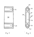
- the new connecting element 20 "according to Figures 3 and 4 has an overall streamlined design over its radial extension, and at its two ends provided with the bores 32, 33 has a radially directed arrowhead 34, 35 which offers less resistance to the passing fluid. Between the area in the amount of holes 32, 33, the connecting element 20 remains "unchanged wide according to the width as it is necessary for the holes 34, 35. As a result of this Forming the connecting element 20 ", there is no longer any edge or groove that can give rise to soiling.
- the connecting element 20 in the middle region, is provided with a cavity 36, whose walls 37, 38, which only provide stability, extend in the same thickness and in parallel.
- the cross-sectional width of the walls 37, 38 in the amount of the cavity 36 corresponds approximately to the width of the walls in the amount of holes 32, 33, as can be seen from Fig. 4.
- the connecting element according to FIGS. 3, 4 is cast from metal and from one piece. Only the holes 32,33 are rework. At least at one point around the drum are the individual screws 29, 30, the foot of which is provided with a hollow thread and its head with a normal fitting into the hollow thread mandrel, to connect by a so-called lock to a circle. At least at this point, the necessary nut screw has a larger diameter.
- a connecting element according to FIG. 3 is no longer usable. At least at this point can fulfill the task, the connecting element consist only of an arrow-shaped bent sheet metal, which has the wall thickness according to the walls 37, 38, but otherwise is hollow for receiving the lock.
Landscapes
- Engineering & Computer Science (AREA)
- Textile Engineering (AREA)
- Mechanical Engineering (AREA)
- General Engineering & Computer Science (AREA)
- Treatment Of Fiber Materials (AREA)
- Paper (AREA)
Description
- Die Erfindung bezieht sich auf eine Vorrichtung zum durchströmenden Behandeln von Textilgut, Vliesen oder Papier mit einem gasförmigen oder flüssigen, in der Vorrichtung umgewälzten Behandlungsmittel mit einer unter Saugzug stehenden, stirnseitig Böden aufweisenden durchlässigen Trommel als Transportelement, welche an ihrem Umfang mit einem Siebgewebe bedeckt ist, wobei zwischen den Böden der Trommel Blechstreifen ungebogen sich von Boden zu Boden gerade erstrecken, deren Breitenausdehnung sich in radialer Richtung erstreckt, und zwischen den Blechstreifen gleichmäßig über die Länge der Trommel verteilt Verbindungselemente angeordnet sind, die dem Sollabstand der unmittelbar benachbarten Blechstreifen entsprechend breit ausgebildet und beidseitig mit den angrenzenden Blechstreifen fest verbunden sind, wobei das jeweilige Verbindungselement stegförmig ausgebildet und in Umfangsrichtung der Trommel mit mindestens einer Bohrung versehen ist, für mindestens eine Schraube und/oder ähnliches mit einem Gewinde versehenes Befestigungselement, und mit den zwei benachbarten Blechstreifen verbindbar ist.
- Eine Vorrichtung dieser Art ist durch die
EP-A-0 315 961 bekannt. Sie hat den unübertroffenen Vorteil, dass sie höchst luftdurchlässig ist, ohne dass dadurch die Stabilität der Trommel vermindert ist. Ohne auf eine Schweißkonstruktion zurückgreifen zu müssen, sind durch die hier vorgesehene Schraubverbindung die in Umfangsrichtung verlaufenden Verbindungselemente mit den längs über die Trommel sich erstreckenden Blechstreifen rund über die Trommel fest verbunden. Die so nachteiligen Gefügeverwandlungen im Metall beim Herstellen von ansonsten notwendigen Schweißnähten sind bei dieser Schraubkonstruktion vermieden. - Die Verbindungselemente gemäß der
EP-A-0 315 961 weisen nur eine der Stabilität genügende Wandstärke auf. Deshalb sind sie stegförmig ausgebildet und im Bereich der Schrauben zur Aufnahme der Schrauben dicker als im mittleren Bereich hergestellt. Es hat sich in der Praxis herausgestellt, dass in den Übergängen von der Wandung in Höhe der Schrauben zu dem mittleren Bereich und auch an anderen Stellen Verschmutzungen auftraten. Flusen setzten sich an den Verbindungselementen fest und hinderten den Durchströmungseffekt. - Es liegt der Erfindung die Aufgabe zugrunde, eine Konstruktion zu finden, bei der eine Verschmutzung an den Verbindungselementen nicht mehr auftritt, mit Vorteil sogar der Durchströmungseffekt vergrößert wird.
- Ausgehend von der Vorrichtung nach der
EP-A-0 315 961 ist die Lösung der gestellten Aufgabe dadurch gefunden, dass das Verbindungselement zumindest über einen Teil seiner radialen Länge strömungsgünstig ausgebildet ist. Dies ist erreicht, wenn der radial außen liegende Bereich des Verbindungselementes pfeilförmig ausgebildet ist, sich in dieser Breite dann bis zur radial inneren Schraube erstreckt und mit Vorteil dann wieder pfeilförmig spitz zuläuft. Zwischen den Schrauben ist die Breite des Körpers nur von geringer, die Stabilität beeinflussender Bedeutung, weswegen hier der Körper aus Gewichtsgründen hohl ausgebildet sein kann. - Eine Vorrichtung der erfindungsgemäßen Art ist in der Zeichnung beispielhaft dargestellt.
- Es zeigen:
- Fig. 1
- Einen Schnitt längs durch eine übliche Siebtrommelvorrichtung, deren Mantel aus einer streifenförmigen Blechstruktur mit Siebgewebe außen besteht,
- Fig. 2
- in vergrößerter Darstellung der Mantel dieser vorbekannten Siebtrommelvorrichtung im gleichen Schnitt wie Fig. 1 und
- Fig. 3
- in vergrößerter Darstellung ein gleicher Schnitt durch ein neues Verbindungselement und
- Fig. 4
- das Verbindungselement nach Fig. 3 mit einem Schnitt senkrecht zu dem nach Fig. 3.
- Die Siebtrommelvorrichtung nach Fig. 1 entspricht der z. B. nach der
EP-A-0 315 961 . Auf die Offenbarung in dieser Schrift wird Bezug genommen. - Eine Siebtrommelvorrichtung besteht grundsätzlich aus einem etwa rechteckigen Gehäuse 1, das durch eine Zwischenwand 2 in einen Behandlungsraum 3 und einen Ventilatorraum 4 unterteilt ist. Im Behandlungsraum 3 ist die Siebtrommel 5 und konzentrisch zu dieser im Ventilatorraum 4 ein Ventilator 6 drehbar gelagert. Selbstverständlich kann der Ventilatorraum auch in einem von dem Siebtrommelgehäuse 1 abgetrennten, hier nicht dargestellten, gesonderten Ventilatorgehäuse angeordnet sein. Jedenfalls setzt der Ventilator das Innere der Trommel 5 unter Saugzug. Auch ist die Trommelkonstruktion an einer Nassbehandlungsvorrichtung, die auch nur zum Absaugen von Flüssigkeit dienen kann, Gegenstand des Patentes. Die Gesamtkonstruktion ist dann entsprechend anzupassen.
- Gemäß der Fig. 1 sind ober- und unterhalb des Ventilators 6 jeweils Heizaggregate 7 angeordnet, die aus mit Heizmedium durchflossenen Rohren bestehen. Die Siebtrommel ist in dem nicht vom Textilgut 9 bedeckten Bereich innen von einer Innenabdeckung 8 gegen den Saugzug abgedeckt. Die wirksame Haut der Siebtrommel ist durch die weiter unten beschriebene Blechstreifenstruktur nach Fig. 2 gebildet. Diese ist außen von einem feinmaschigem Sieb 19 umschlungen, das an der Stirnseite der Trommel an den beiden Böden 11, 12 gespannt gehalten ist.
- Die vorbekannte Blechstreifenstruktur besteht aus axial ausgerichteten Blechstreifen 10, deren radial ausgerichtete Höhe aus Fig. 2 hervorgeht. Damit liegt also der siebförmige Belag 19 nur auf den radial außen angeordneten Kanten der Blechstreifen 10 auf. Die Blechstreifen 10 sind mit einem definierten Abstand nebeneinander an den beiden Böden 11, 12 durch nicht dargestellte Schrauben befestigt. Damit dieser Abstand über die Breite der Trommel fixiert ist, sind als Abstandhalter dienende, im ganzen mit 20 bezeichnete Verbindungselemente vorgesehen, die mittels Schrauben 29, 29' und 30, 30' mit den Blechstreifen 10 verbunden sind.
- Die Verbindungselemente 20 weisen gemäß Fig. 2 an ihren Anlageflächen an den Blechstreifen 10 einen rechteckigen Flansch 22 auf. Der radial außen sich erstreckende Bereich des Verbindungselementes 20 besteht aus dem Steg 24. Radial innen weist das Verbindungselement 20 einen verbreiterten Fuß 28 auf, während der übrige Bereich 26 des Verbindungselementes mit Ausnahme in Höhe der Schraubendurchgänge 25, 27 schmal im Querschnitt ausgebildet ist. Die Verbindung der Verbindungselemente 20 untereinander erfolgt mittels Stangen 29, 29' und 30 30' mit Gewinden zumindest an den beiden Enden, auf die dann die Muttern 31 innerhalb eines Verbindungselementes 20' aufgeschraubt werden.
- Das neue Verbindungselement 20" nach Fig. 3 und 4 ist über seine radiale Erstreckung insgesamt stromlinienförmig ausgebildet. Es weist an seinen beiden mit den Bohrungen 32, 33 versehenen Enden eine radial gerichtete Pfeilspitze 34, 35 auf, die dem vorbeiströmenden Fluid weniger Widerstand bietet. Zwischen dem Bereich in Höhe der Bohrungen 32, 33 verbleibt das Verbindungselement 20" unverändert breit entsprechend der Breite wie sie für die Bohrungen 34, 35 nötig ist. Infolge dieser Formgebung des Verbindungselementes 20" ist keine Kante oder Rille mehr vorhanden, die Anlass für eine Verschmutzung geben kann.
- Um eine Gewichtsverminderung zu erzielen, ist in dem mittleren Bereich das Verbindungselement 20" mit einem Hohlraum 36 versehen, dessen nur der Stabilität genügenden Wandungen 37, 38 gleich dick und parallel verlaufen.
- Die Querschnittsbreite der Wandungen 37, 38 in Höhe des Hohlraumes 36 entspricht etwa auch der Breite der Wandungen in Höhe der Bohrungen 32, 33, wie es aus der Fig. 4 zu entnehmen ist.
- Das Verbindungselement gemäß Fig. 3, 4 ist aus Metall und aus einem Stück gegossen. Lediglich die Bohrungen 32,33 sind nachzuarbeiten. Zumindest an einer Stelle rund um die Trommel sind die einzelnen Schrauben 29, 30, deren Fuß mit einem Hohlgewinde und deren Kopf mit einem normalen in das Hohlgewinde passenden Dorngewinde versehen ist, durch ein sogenanntes Schloss zu einem Kreis zu verbinden. Zumindest an dieser einen Stelle hat die notwendige Mutterschraube einen größeren Durchmesser. Ein Verbindungselement gemäß Fig. 3 ist nicht mehr brauchbar. Zumindest an dieser Stelle kann zur Erfüllung der gestellten Aufgabe das Verbindungselement lediglich aus einem pfeilförmig gebogenen Blech bestehen, das die Wandstärke gemäß der Wandungen 37, 38 aufweist, ansonsten aber zur Aufnahme des Schlosses hohl ist.
Claims (5)
- Vorrichtung zum durchströmenden Behandeln von Textilgut, Vliesen oder Papier mit einem gasförmigen oder flüssigen Behandlungsmittel in einer durchlässigen Trommel (5), welche mit einem Siebgewebe (9) bedeckt ist, wobei sich zwischen den Böden (11, 12) der Trommel (5) gerade Blechstreifen (10) befinden, deren Breitenausdehnung sich in radialer Richtung erstreckt, und zwischen den Blechstreifen (10) gleichmäßig über die Länge der Trommel (5) verteilt steg förmige Verbindungselemente (20) angeordnet sind, die beidseitig mit den angrenzenden Blechstreifen (10) fest verbunden und mit mehr als einer Bohrung für Schrauben (29, 29'; 30, 30') und/oder ähnliche mit einem Gewinde versehenen Befestigungselemente versehen sind, wodurch zwei benachbarte Blechstreifen (10) (20) verbindbar sind, dadurch gekennzeichnet, dass die radial innen- und/oder außen angeordneten Flanken des Verbindungselements (20") pfeilförmig ausgebildet sind und dieses zwischen den Schraubenlöchern gleich breit wie in Höhe der Bohrungen (34, 35) ist.
- Vorrichtung nach Anspruch 1, dadurch gekennzeichnet, dass das Verbindungselement (20") in Höhe zwischen den Bohrungen (34, 35) mit einem parallel zu den Bohrungen (34, 35) verlaufenden Hohlraum (36) versehen ist.
- Vorrichtung nach Anspruch 2, dadurch gekennzeichnet, dass das Verbindungselement (20") in Höhe des Hohlraumes nur mit einer der Stabilität des Verbindungselementes (20") ausreichenden Wandung (37, 38) versehen ist.
- Vorrichtung nach Anspruch 3, dadurch gekennzeichnet, dass die beidseitig des Hohlraumes (36) vorgesehenen Wandung (37, 38) parallel verlaufen.
- Vorrichtung nach einem der vorhergehenden Ansprüche, dadurch gekennzeichnet, dass das Verbindungselement lediglich aus einem pfeilförmig gebogenen Blech besteht, das die beiden Schrauben (29, 30) oder deren Teile abdeckend umfasst.
Applications Claiming Priority (2)
| Application Number | Priority Date | Filing Date | Title |
|---|---|---|---|
| DE10353115A DE10353115A1 (de) | 2003-11-12 | 2003-11-12 | Vorrichtung an einer von außen nach innen durchströmten Siebtrommel |
| PCT/EP2004/052842 WO2005047587A1 (de) | 2003-11-12 | 2004-11-08 | Vorrichtung an einer von aussen nach innen durchströmten siebtrommel |
Publications (2)
| Publication Number | Publication Date |
|---|---|
| EP1685287A1 EP1685287A1 (de) | 2006-08-02 |
| EP1685287B1 true EP1685287B1 (de) | 2008-01-23 |
Family
ID=34559635
Family Applications (1)
| Application Number | Title | Priority Date | Filing Date |
|---|---|---|---|
| EP04818413A Expired - Lifetime EP1685287B1 (de) | 2003-11-12 | 2004-11-08 | Vorrichtung an einer von aussen nach innen durchströmten siebtrommel |
Country Status (4)
| Country | Link |
|---|---|
| US (1) | US20070039356A1 (de) |
| EP (1) | EP1685287B1 (de) |
| DE (2) | DE10353115A1 (de) |
| WO (1) | WO2005047587A1 (de) |
Family Cites Families (7)
| Publication number | Priority date | Publication date | Assignee | Title |
|---|---|---|---|---|
| EP0315961B1 (de) * | 1987-11-10 | 1992-11-04 | FLEISSNER Maschinenfabrik AG | Vorrichtung zum durchströmenden Behandeln von Textilgut od. dgl. |
| DE3802791A1 (de) * | 1988-01-30 | 1989-08-10 | Fleissner Maschf Ag | Vorrichtung zum durchstroemenden behandeln von textilgut, papier od. dgl. |
| DE3905738A1 (de) * | 1989-02-24 | 1990-08-30 | Fleissner Maschf Ag | Vorrichtung zum durchstroemenden behandeln von textilgut, papier od. dgl. |
| US4970879A (en) * | 1988-06-24 | 1990-11-20 | Fleissner Maschinenfabrik Ag | Apparatus for flow-through treatment of textile material, paper, or the like |
| US4912945A (en) * | 1988-06-24 | 1990-04-03 | Fleissner Maschinenfabrik Ag | Device for through-flow treatment of fabric, paper, or the like |
| DE4413779A1 (de) * | 1994-04-20 | 1995-10-26 | Fleissner Maschf Gmbh Co | Vorrichtung zum durchströmenden Behandeln von Textilgut oder dergleichen |
| DE10253352A1 (de) * | 2002-11-14 | 2004-05-27 | Fleissner Gmbh & Co. Maschinenfabrik | Vorrichtung zum durchströmenden oder beaufschlagenden Behandeln von bahnförmiger Ware |
-
2003
- 2003-11-12 DE DE10353115A patent/DE10353115A1/de not_active Withdrawn
-
2004
- 2004-11-08 US US10/578,296 patent/US20070039356A1/en not_active Abandoned
- 2004-11-08 WO PCT/EP2004/052842 patent/WO2005047587A1/de not_active Ceased
- 2004-11-08 EP EP04818413A patent/EP1685287B1/de not_active Expired - Lifetime
- 2004-11-08 DE DE502004006075T patent/DE502004006075D1/de not_active Expired - Lifetime
Also Published As
| Publication number | Publication date |
|---|---|
| DE502004006075D1 (de) | 2008-03-13 |
| US20070039356A1 (en) | 2007-02-22 |
| DE10353115A1 (de) | 2005-06-09 |
| EP1685287A1 (de) | 2006-08-02 |
| WO2005047587A1 (de) | 2005-05-26 |
Similar Documents
| Publication | Publication Date | Title |
|---|---|---|
| EP0678613B1 (de) | Vorrichtung zum durchströmenden Behandeln von Textilgut od. Dgl. | |
| DE3907421C2 (de) | ||
| EP1574333B1 (de) | Rotationskörper einer Druckmaschine | |
| EP0315961B1 (de) | Vorrichtung zum durchströmenden Behandeln von Textilgut od. dgl. | |
| DE9104669U1 (de) | Aus einzelnen Scheibenfiltersegmenten bestehendes Scheibenfilter | |
| DE2460167B2 (de) | Spaltsieb mit auswechselbaren Siebstäben | |
| EP1685287B1 (de) | Vorrichtung an einer von aussen nach innen durchströmten siebtrommel | |
| DE69810151T2 (de) | Rahmenanordnung für plattenwärmetauscher | |
| EP0385208B1 (de) | Vorrichtung zum durchströmenden Behandeln von Textilgut, Papier od. dgl. | |
| DE3802791A1 (de) | Vorrichtung zum durchstroemenden behandeln von textilgut, papier od. dgl. | |
| DE8503846U1 (de) | Rohrschelle | |
| EP1563134A1 (de) | Vorrichtung zum durchstr menden oder beaufschlagenden behand eln von bahnf rmiger ware | |
| DE3121969C2 (de) | Entwässerungswalze einer Siebpresse | |
| DE2115156C3 (de) | Saugwalze, insbesondere für Papiermaschinen | |
| DE2225562C3 (de) | Schrumpfhülse zum Stabilisieren oder Färben von Textilfäden | |
| DE1946376C2 (de) | Saugwalze | |
| EP1301659B1 (de) | Vorrichtung zum durchströmenden, kontinuierlichen behandeln von textilgut od. dgl | |
| DE20100730U1 (de) | Griff für Möbel u.dgl. | |
| DE3109481C2 (de) | Zylindrische Filterhülse, insbesondere für Hochdruckfilter | |
| EP1641614A1 (de) | Seiherstab mit distanzelement sowie vorrichtung zum abpressen | |
| DE29501187U1 (de) | Förderbandabstreifer | |
| DE202020006012U1 (de) | Aufnahmevorrichtung an einer Erntemaschine | |
| DE20012395U1 (de) | Autowaschbürste | |
| DE8519565U1 (de) | Krankenbett | |
| DE20100731U1 (de) | Griff für Möbel o.dgl. |
Legal Events
| Date | Code | Title | Description |
|---|---|---|---|
| PUAI | Public reference made under article 153(3) epc to a published international application that has entered the european phase |
Free format text: ORIGINAL CODE: 0009012 |
|
| 17P | Request for examination filed |
Effective date: 20060612 |
|
| AK | Designated contracting states |
Kind code of ref document: A1 Designated state(s): AT BE BG CH CY CZ DE DK EE ES FI FR GB GR HU IE IS IT LI LU MC NL PL PT RO SE SI SK TR |
|
| DAX | Request for extension of the european patent (deleted) | ||
| RBV | Designated contracting states (corrected) |
Designated state(s): DE FI FR SE |
|
| GRAP | Despatch of communication of intention to grant a patent |
Free format text: ORIGINAL CODE: EPIDOSNIGR1 |
|
| GRAS | Grant fee paid |
Free format text: ORIGINAL CODE: EPIDOSNIGR3 |
|
| GRAA | (expected) grant |
Free format text: ORIGINAL CODE: 0009210 |
|
| AK | Designated contracting states |
Kind code of ref document: B1 Designated state(s): DE FI FR SE |
|
| REF | Corresponds to: |
Ref document number: 502004006075 Country of ref document: DE Date of ref document: 20080313 Kind code of ref document: P |
|
| REG | Reference to a national code |
Ref country code: SE Ref legal event code: TRGR |
|
| ET | Fr: translation filed | ||
| PLBE | No opposition filed within time limit |
Free format text: ORIGINAL CODE: 0009261 |
|
| STAA | Information on the status of an ep patent application or granted ep patent |
Free format text: STATUS: NO OPPOSITION FILED WITHIN TIME LIMIT |
|
| 26N | No opposition filed |
Effective date: 20081024 |
|
| PGFP | Annual fee paid to national office [announced via postgrant information from national office to epo] |
Ref country code: FI Payment date: 20091125 Year of fee payment: 6 Ref country code: SE Payment date: 20091123 Year of fee payment: 6 |
|
| REG | Reference to a national code |
Ref country code: SE Ref legal event code: EUG |
|
| PG25 | Lapsed in a contracting state [announced via postgrant information from national office to epo] |
Ref country code: FI Free format text: LAPSE BECAUSE OF NON-PAYMENT OF DUE FEES Effective date: 20101108 |
|
| PG25 | Lapsed in a contracting state [announced via postgrant information from national office to epo] |
Ref country code: SE Free format text: LAPSE BECAUSE OF NON-PAYMENT OF DUE FEES Effective date: 20101109 |
|
| PGFP | Annual fee paid to national office [announced via postgrant information from national office to epo] |
Ref country code: DE Payment date: 20131122 Year of fee payment: 10 |
|
| PGFP | Annual fee paid to national office [announced via postgrant information from national office to epo] |
Ref country code: FR Payment date: 20131118 Year of fee payment: 10 |
|
| REG | Reference to a national code |
Ref country code: DE Ref legal event code: R119 Ref document number: 502004006075 Country of ref document: DE |
|
| REG | Reference to a national code |
Ref country code: FR Ref legal event code: ST Effective date: 20150731 |
|
| PG25 | Lapsed in a contracting state [announced via postgrant information from national office to epo] |
Ref country code: DE Free format text: LAPSE BECAUSE OF NON-PAYMENT OF DUE FEES Effective date: 20150602 |
|
| PG25 | Lapsed in a contracting state [announced via postgrant information from national office to epo] |
Ref country code: FR Free format text: LAPSE BECAUSE OF NON-PAYMENT OF DUE FEES Effective date: 20141201 |