EP1685941B1 - Adaptor für einen Extrusionskopf für das Blasformen von Vorformlingen - Google Patents
Adaptor für einen Extrusionskopf für das Blasformen von Vorformlingen Download PDFInfo
- Publication number
- EP1685941B1 EP1685941B1 EP06000704A EP06000704A EP1685941B1 EP 1685941 B1 EP1685941 B1 EP 1685941B1 EP 06000704 A EP06000704 A EP 06000704A EP 06000704 A EP06000704 A EP 06000704A EP 1685941 B1 EP1685941 B1 EP 1685941B1
- Authority
- EP
- European Patent Office
- Prior art keywords
- adaptor device
- extrusion head
- inlet
- molten material
- annular element
- Prior art date
- Legal status (The legal status is an assumption and is not a legal conclusion. Google has not performed a legal analysis and makes no representation as to the accuracy of the status listed.)
- Expired - Lifetime
Links
Images



Classifications
-
- B—PERFORMING OPERATIONS; TRANSPORTING
- B29—WORKING OF PLASTICS; WORKING OF SUBSTANCES IN A PLASTIC STATE IN GENERAL
- B29C—SHAPING OR JOINING OF PLASTICS; SHAPING OF MATERIAL IN A PLASTIC STATE, NOT OTHERWISE PROVIDED FOR; AFTER-TREATMENT OF THE SHAPED PRODUCTS, e.g. REPAIRING
- B29C48/00—Extrusion moulding, i.e. expressing the moulding material through a die or nozzle which imparts the desired form; Apparatus therefor
- B29C48/03—Extrusion moulding, i.e. expressing the moulding material through a die or nozzle which imparts the desired form; Apparatus therefor characterised by the shape of the extruded material at extrusion
- B29C48/09—Articles with cross-sections having partially or fully enclosed cavities, e.g. pipes or channels
-
- B—PERFORMING OPERATIONS; TRANSPORTING
- B29—WORKING OF PLASTICS; WORKING OF SUBSTANCES IN A PLASTIC STATE IN GENERAL
- B29C—SHAPING OR JOINING OF PLASTICS; SHAPING OF MATERIAL IN A PLASTIC STATE, NOT OTHERWISE PROVIDED FOR; AFTER-TREATMENT OF THE SHAPED PRODUCTS, e.g. REPAIRING
- B29C48/00—Extrusion moulding, i.e. expressing the moulding material through a die or nozzle which imparts the desired form; Apparatus therefor
- B29C48/001—Combinations of extrusion moulding with other shaping operations
- B29C48/0018—Combinations of extrusion moulding with other shaping operations combined with shaping by orienting, stretching or shrinking, e.g. film blowing
-
- B—PERFORMING OPERATIONS; TRANSPORTING
- B29—WORKING OF PLASTICS; WORKING OF SUBSTANCES IN A PLASTIC STATE IN GENERAL
- B29C—SHAPING OR JOINING OF PLASTICS; SHAPING OF MATERIAL IN A PLASTIC STATE, NOT OTHERWISE PROVIDED FOR; AFTER-TREATMENT OF THE SHAPED PRODUCTS, e.g. REPAIRING
- B29C48/00—Extrusion moulding, i.e. expressing the moulding material through a die or nozzle which imparts the desired form; Apparatus therefor
- B29C48/16—Articles comprising two or more components, e.g. co-extruded layers
- B29C48/18—Articles comprising two or more components, e.g. co-extruded layers the components being layers
- B29C48/19—Articles comprising two or more components, e.g. co-extruded layers the components being layers the layers being joined at their edges
-
- B—PERFORMING OPERATIONS; TRANSPORTING
- B29—WORKING OF PLASTICS; WORKING OF SUBSTANCES IN A PLASTIC STATE IN GENERAL
- B29C—SHAPING OR JOINING OF PLASTICS; SHAPING OF MATERIAL IN A PLASTIC STATE, NOT OTHERWISE PROVIDED FOR; AFTER-TREATMENT OF THE SHAPED PRODUCTS, e.g. REPAIRING
- B29C48/00—Extrusion moulding, i.e. expressing the moulding material through a die or nozzle which imparts the desired form; Apparatus therefor
- B29C48/16—Articles comprising two or more components, e.g. co-extruded layers
- B29C48/18—Articles comprising two or more components, e.g. co-extruded layers the components being layers
- B29C48/21—Articles comprising two or more components, e.g. co-extruded layers the components being layers the layers being joined at their surfaces
-
- B—PERFORMING OPERATIONS; TRANSPORTING
- B29—WORKING OF PLASTICS; WORKING OF SUBSTANCES IN A PLASTIC STATE IN GENERAL
- B29C—SHAPING OR JOINING OF PLASTICS; SHAPING OF MATERIAL IN A PLASTIC STATE, NOT OTHERWISE PROVIDED FOR; AFTER-TREATMENT OF THE SHAPED PRODUCTS, e.g. REPAIRING
- B29C48/00—Extrusion moulding, i.e. expressing the moulding material through a die or nozzle which imparts the desired form; Apparatus therefor
- B29C48/25—Component parts, details or accessories; Auxiliary operations
- B29C48/30—Extrusion nozzles or dies
- B29C48/3001—Extrusion nozzles or dies characterised by the material or their manufacturing process
-
- B—PERFORMING OPERATIONS; TRANSPORTING
- B29—WORKING OF PLASTICS; WORKING OF SUBSTANCES IN A PLASTIC STATE IN GENERAL
- B29C—SHAPING OR JOINING OF PLASTICS; SHAPING OF MATERIAL IN A PLASTIC STATE, NOT OTHERWISE PROVIDED FOR; AFTER-TREATMENT OF THE SHAPED PRODUCTS, e.g. REPAIRING
- B29C48/00—Extrusion moulding, i.e. expressing the moulding material through a die or nozzle which imparts the desired form; Apparatus therefor
- B29C48/25—Component parts, details or accessories; Auxiliary operations
- B29C48/30—Extrusion nozzles or dies
- B29C48/32—Extrusion nozzles or dies with annular openings, e.g. for forming tubular articles
- B29C48/325—Extrusion nozzles or dies with annular openings, e.g. for forming tubular articles being adjustable, i.e. having adjustable exit sections
-
- B—PERFORMING OPERATIONS; TRANSPORTING
- B29—WORKING OF PLASTICS; WORKING OF SUBSTANCES IN A PLASTIC STATE IN GENERAL
- B29C—SHAPING OR JOINING OF PLASTICS; SHAPING OF MATERIAL IN A PLASTIC STATE, NOT OTHERWISE PROVIDED FOR; AFTER-TREATMENT OF THE SHAPED PRODUCTS, e.g. REPAIRING
- B29C48/00—Extrusion moulding, i.e. expressing the moulding material through a die or nozzle which imparts the desired form; Apparatus therefor
- B29C48/25—Component parts, details or accessories; Auxiliary operations
- B29C48/36—Means for plasticising or homogenising the moulding material or forcing it through the nozzle or die
- B29C48/49—Means for plasticising or homogenising the moulding material or forcing it through the nozzle or die using two or more extruders to feed one die or nozzle
-
- B—PERFORMING OPERATIONS; TRANSPORTING
- B29—WORKING OF PLASTICS; WORKING OF SUBSTANCES IN A PLASTIC STATE IN GENERAL
- B29C—SHAPING OR JOINING OF PLASTICS; SHAPING OF MATERIAL IN A PLASTIC STATE, NOT OTHERWISE PROVIDED FOR; AFTER-TREATMENT OF THE SHAPED PRODUCTS, e.g. REPAIRING
- B29C49/00—Blow-moulding, i.e. blowing a preform or parison to a desired shape within a mould; Apparatus therefor
- B29C49/02—Combined blow-moulding and manufacture of the preform or the parison
- B29C49/04—Extrusion blow-moulding
- B29C49/04102—Extrusion blow-moulding extruding the material continuously
Definitions
- the present invention refers to the field of blow-moulding machines for blow-moulding of polymer materials with a continuous extrusion head.
- a continuous extrusion head for blow-moulding of parisons always has some substantial differences according to the particular application for which it is intended.
- the object of the present invention is to eliminate the drawbacks of the prior art, providing a continuous extrusion head adaptor device for blow-moulding of parisons that makes it possible to pass from one production configuration to another without having to change the entire extrusion head.
- the adaptor device according to the invention is suitable for application to a continuous extrusion head for blow-moulding of parisons.
- the extrusion head comprises:
- the adaptor device has a substantially annular shape, is mounted removably in the extrusion head, and is disposed around said core of the extrusion head, so as to form a space for passage of the molten material between the inner side surface thereof and the outer side surface of the core.
- the adaptor device further comprises at least one inlet supplied by the distributor of said secondary extruder and communicating with at least one outlet opening into said space formed by the adaptor device and the core of the extrusion head.
- Such an adaptor device presents various advantages. In fact it can be configured according to the type of production to be obtained and is easy and rapid to mount and remove, without the need to intervene on other parts of the extrusion head.
- the head 1 Associated with the head 1 are a main extruder 2 and a secondary extruder 3.
- the main extruder 2 has an extrusion screw 4 disposed in the top part of the head 1 with a horizontal axis.
- the secondary extruder 3 has a smaller extrusion screw 5 disposed in the central part of the head with a vertical axis.
- the molten material is fed to the main extruder 2 in an upturned L-shaped inlet duct 6 formed in the top part of the head 1.
- the inlet duct 6 leads to a distributor 7 which distributes the molten material into a cylindrical space 9 defined by means of a core or male 8 disposed axially in the head 1. In this manner the molten material in the space 9 takes on the typical tubular shape of the parison.
- the secondary extruder 3 feeds the molten material towards an inlet duct and a distributor (not shown in the figures) formed in the central part of the head 1.
- the distributor of the secondary extruder 3 distributes the molten material into an adaptor device 10 mounted removeably in the extrusion head 1.
- the adaptor device 10 has a substantially annular shape and is disposed around the core 8 of the extrusion head 1. In this manner, an annular space 100, communicating with the cylindrical space 9 through which the plastic material coming from the main extruder 2 passes, is defined between the inner side surface of the adaptor device 10 and the outer side surface of the core 8.
- the adaptor device 10 has outlet ducts which open into the space 100 to achieve coextrusion of the molten material coming from the main extruder 2 and the molten material coming from the secondary extruder 3.
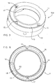
- FIGS 3 - 6 show an adaptor device designated as a whole with reference numeral 10A.
- the adaptor device 10A can be used for production of "deco type" coextruded parisons, therefore it must be able to provide an outer tubular layer of plastic material which is superimposed on the inner tubular layer of plastic material coming form the main extruder 2.
- the adaptor device 10A comprises a top annular element 11 and a bottom annular element 12 which can be superimposed on each other and coupled together.
- the top annular element 11 comprises an inlet channel 13 formed in the top surface thereof.
- the inlet channel 13 extends for an arc of a circle with an angle of 180° and has at its ends two inlet holes 14 with vertical axes, disposed in diametrically opposite positions.
- a cusp or wedge 15 In the central part of the inlet channel 13 is formed a cusp or wedge 15 with its tip facing upward and disposed at an angular distance of 90° from the two inlet holes 14, so as to divide the channel 13 into two equal portions.
- the cusp 15 is disposed beneath the inlet duct for the molten material coming from the auxiliary extruder 3, therefore it has the function of distributing the molten material equally into the two portions of the channel 13.
- the inlet holes 14 lead to an annular distribution channel 16 formed in the bottom surface of the top element 11.
- the distribution channel 16 extends along the entire annular element 11 for an angle of 360°.
- the cusps 17 facing towards the centre of the upper annular element 11 are formed in the distribution channel 16.
- the cusps 17 are disposed in diametrically opposite positions and spaced 90° from the inlet holes 14.
- the cusps 17 form a narrowing in the distribution channel 16 and thus serve to avoid stagnation of molten material in the positions furthest from the inlet holes 14.
- the distribution channel 16 is defined by two substantially elliptical edges 18 and 19, with a major axis passing through the vertical axes of the two inlet holes 14.
- the inner elliptical edge 19 of the channel 16 joins with the inner circular edge 20 of the top element 11.
- the distribution channel 16 has an area of maximum width near the inlet holes 14 in which there is a greater flow of molten material and narrows gradually until it reaches an area of minimum width near the cusps 17 in which there is a lesser flow of molten material.
- This configuration of the distribution channel 16 makes it possible to have a constant pressure drop in the molten material, evenly distributed over the whole circumference defined by the inner edge 20 of the top annular element 11.
- the bottom element 12 has in its upper surface an annular distribution channel 36, substantially the same as the distribution channel 16 of the top element 11. In this manner, when the top annular element 11 is superimposed on the bottom annular element 12, the two respective distribution channels 16 and 36 match perfectly, forming a single channel with a substantially circular section.
- Two upwardly facing cusps or wedges 34 disposed in diametrically opposite positions are formed in the distribution channel 36 of the bottom annular element 12.
- the cusps 34 are destined to be disposed beneath the inlet holes 14 of the top element 11 and serve to distribute the molten material evenly in the channel 36.
- Another two cusps or wedges 37 facing towards the centre of the bottom annular element 12 and disposed in diametrically opposite positions are formed in the distribution channel 36.
- the cusps 37 are destined to be disposed beneath the cusps 17 of the top element 11 and serve to avoid stagnation of the molten material in the channel 36.
- the bottom annular element 12 has an inner top edge 40 destined to couple with the inner bottom edge 20 of the top annular element 11. As shown in Figure 3 , between the inner bottom edge 20 of the top annular element 11 and the inner top edge 40 of the bottom annular element 12, a circumferential gap 41 is left, which allows the molten material to emerge in a tubular shape.
- two threaded holes 42 are formed in the bottom surface of the bottom annular element 12, disposed in a diametrically opposite position to receive fixing screws.
- a slot 43 destined to be disposed to coincide with a corresponding slot 44 disposed in the top element 11 to allow the two elements 11 and 12 to be put in register is provided on the side surface of the bottom element 12.
- FIGs 7 and 8 an adaptor device designated as a whole with reference numeral 10B is illustrated.
- the adaptor device 10B can be used for production of coextruded "multi-stripe type" coextruded parisons; Therefore it must be able to provide a plurality of outer vertical stripes of plastic material which are superimposed on the inner tubular layer of material coming from the main extruder 2.
- the adaptor device 10B comprises a top annular element 11 and a bottom annular element 12 substantially similar to those of the adaptor 10A. The only difference is represented by the fact that a plurality of slots 50 alternating with a plurality of protruding parts 51 are formed in the inner edge of the top annular element 11.
- the protruding parts 51 of the inner bottom edge 20 of the top element 11 abut on the inner top edge 40 of the bottom element 12 and thus the molten material can emerge from the distribution channel 16 through the slots 50, so as to form a plurality of vertical lines.
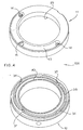
- FIGS 9 - 11 show an adaptor device designated as a whole with reference numeral 10C.
- the adaptor device 10C can be used for production of "view stripe type" coextruded parisons, therefore it must be able to provide a transparent stripe of plastic material that is not superimposed on the layer of tubular plastic material coming from the main extruder 2.
- the adaptor device 10C comprises a single annular element 60 which has in its top surface an inlet channel 61 which extends for an arc of a circle subtended by an angle of 90° at the centre.
- An inlet hole 62 is formed at one end of the channel 61 with a vertical axis which communicates with a distribution duct 71 formed in a distribution block 70 inserted in a radial hole of the side wall of the annular element 60.
- the radial distribution duct 71 is opened in the inner side surface of the annular element 60. In this manner the distribution duct 71 can open into the annular space 100 ( Figure 2 ) defined between the core 8 and the annular element 60.
- the distribution block 70 has a cover 72 disposed above the outlet opening of the radial duct 71.
- the cover 72 is shaped as an upwardly facing cusp or wedge and protrudes radially towards the centre of in the annular space 100 ( Figure 2 ) until it comes into contact with the core 8 of the extrusion head.
- the transparent stripe can be generated on the right-hand side or on the left-hand side of the parison.
- Figure 12 shows an adaptor device according to the invention designated as a whole by reference numeral 10D.
- the adaptor device 10D can be used for production of "view stripe type" coextruded parisons in which the transparent stripe can be disposed either on the left-hand side or on the right-hand side of the parison without the need to remove the adaptor device 10D.
- the adaptor device 10C comprises a single annular element 60 which has in its top surface two inlet channels 61s and 61 d which each extend for an arc of a circle subtended by an angle at the centre of about 90°.
- the two channels 61s and 61 d are separated from each other by a small dividing wall 65.
- the channels 61s and 61d end in respective inlet holes 62s and 62d which lead to respective distribution blocks 70 identical to what was described previously.
- Two flat abutment surfaces 66s and 66d disposed on the right and on the left with respect to the dividing wall 65 are formed in the outer lateral surface of the annular element 60.
- the tips of the respective adjustment screws 80s and 80d adjustable by the user abut on the abutment surfaces 66s and 66d.
- the supply duct for the molten material coming from the auxiliary extruder 3 is situated level with the dividing wall 65 on the annular element 60. Then, by tightening the screw 80d and loosening the screw 80 the annular element 60 is caused to rotate in an anti-clockwise direction with respect to Figure 12 . As a result the supply duct will supply the channel 61s and the transparent stripe will be formed in the left-hand side of the parison. Clearly in this case the distribution block 70 beneath the inlet hole 62d is removed.
Landscapes
- Engineering & Computer Science (AREA)
- Mechanical Engineering (AREA)
- Manufacturing & Machinery (AREA)
- Blow-Moulding Or Thermoforming Of Plastics Or The Like (AREA)
- Processing And Handling Of Plastics And Other Materials For Molding In General (AREA)
- Extrusion Moulding Of Plastics Or The Like (AREA)
Claims (4)
- Adaptorvorrichtung (10D) für einen Extrusionskopf für das Blasformen von Vorformlingen, der Extrusionskopf (1) umfassend:- einen Hauptextruder (2), der das geschmolzene Material über einen Verteiler (7) in einen röhrenförmigen Raum (9) zuführt, der durch einen Kern oder Stecker (8) innerhalb des Extrusionskopfs (1) definiert ist, und- einen Nebenextruder (3), der das geschmolzene Material über einen Verteiler in die Adaptorvorrichtung (10) zuführt,
wobei die Adaptorvorrichtung (10) ein einzelnes ringförmiges Element (60) umfasst, das- eine im Wesentlichen ringförmige Form aufweist,- derart in dem Extrusionskopf angebracht ist und um den Kern (8) des Extrusionskopfs angeordnet ist, dass es einen ringförmigen Raum (100) zum Durchgang von geschmolzenem Material zwischen seiner Innenfläche und der Außenfläche des Kerns (8) ausbildet, und- zumindest einen Einlass (61s, 61d) umfasst, der von dem Verteiler des Nebenextruders (3) gespeist ist und mit zumindest einer Auslassöffnung (71) in den ringförmigen Raum (100) in Verbindung steht,
dadurch gekennzeichnet, dass
sie zwei Einasskanäle (61s, 61d) umfasst, die auf der oberen Oberfläche davon ausgebildet sind und durch eine Trennwand (65) getrennt sind und in jeweiligen Einlasslöchern (62s, 62d) distal von der Trennwand (65) enden,- wobei die Einlasslöcher (62s, 62d) mit jeweiligen radialen Verteilungskanälen (71) in Verbindung stehen, die unterhalb von jeweiligen Abdeckungen (72) münden, welche radial in dem ringförmigen Raum (100) zum Ermöglichen eines Sichtstreifenbaus in diametral gegenüberliegenden Positionen verlaufen,- wobei das ringförmige Element (60) zum Leiten des geschmolzenen Materials in einen der zwei Einlasskanäle (61 s, 61 d) drehbar ist. - Adaptorvorrichtung (10D) nach Anspruch 1, dadurch gekennzeichnet, dass in der Seitenwand des ringförmigen Elements (60) zwei flache Angrenzflächen (66s, 66d) ausgebildet sind, an denen die Spitzen der jeweiligen Stellschrauben (80s, 80d) zum Steuern der Drehung des ringförmigen Elements (60) wirken.
- Adaptorvorrichtung (10D) nach einem der Ansprüche 1 oder 2, dadurch gekennzeichnet, dass zumindest ein Einlass (61s, 61d) zumindest einen Kanal (61s, 61d) umfasst, der als Kreisbogen geformt ist und mit zumindest einem Einlassloch (62s, 62d) in Verbindung steht, welches zu einem Verteilungskanal (71) führt, der in der Adaptorvorrichtung ausgebildet ist und mit dem Auslass (41; 50; 71) der Adaptorvorrichtung in Verbindung steht.
- Extrusionskopf für das Blasformen von Vorformlingen, dadurch gekennzeichnet, das er eine Adaptorvorrichtung (10D) nach einem der vorhergehenden Ansprüche umfasst.
Applications Claiming Priority (1)
| Application Number | Priority Date | Filing Date | Title |
|---|---|---|---|
| IT000103A ITMI20050103A1 (it) | 2005-01-26 | 2005-01-26 | Dispositivo adattatore per testa di estrusione in continuo per il soffiaggio di corpi cavi |
Publications (3)
| Publication Number | Publication Date |
|---|---|
| EP1685941A2 EP1685941A2 (de) | 2006-08-02 |
| EP1685941A3 EP1685941A3 (de) | 2007-06-27 |
| EP1685941B1 true EP1685941B1 (de) | 2012-06-13 |
Family
ID=36384497
Family Applications (1)
| Application Number | Title | Priority Date | Filing Date |
|---|---|---|---|
| EP06000704A Expired - Lifetime EP1685941B1 (de) | 2005-01-26 | 2006-01-13 | Adaptor für einen Extrusionskopf für das Blasformen von Vorformlingen |
Country Status (3)
| Country | Link |
|---|---|
| EP (1) | EP1685941B1 (de) |
| ES (1) | ES2389494T3 (de) |
| IT (1) | ITMI20050103A1 (de) |
Families Citing this family (2)
| Publication number | Priority date | Publication date | Assignee | Title |
|---|---|---|---|---|
| CN114030156B (zh) * | 2021-10-27 | 2023-11-03 | 山东卓越管业有限公司 | 一种纳米抗菌管材的配方及加工其的单螺杆挤出机 |
| CN116039039A (zh) * | 2023-01-10 | 2023-05-02 | 安徽凌宇电缆科技有限公司 | 一种用于电缆标识线加工的挤出模具 |
Family Cites Families (3)
| Publication number | Priority date | Publication date | Assignee | Title |
|---|---|---|---|---|
| JPH0611516B2 (ja) * | 1986-06-04 | 1994-02-16 | エクセル株式会社 | 部分的に組成の異なる中空成形品及びその製造装置 |
| US5221540A (en) * | 1992-06-17 | 1993-06-22 | Hoover Universal, Inc. | Extrusion head with adjustable view stripe positioning |
| US6090338A (en) * | 1996-08-23 | 2000-07-18 | Moeller Plast Gmbh | Method and devices for coating a carrier part |
-
2005
- 2005-01-26 IT IT000103A patent/ITMI20050103A1/it unknown
-
2006
- 2006-01-13 EP EP06000704A patent/EP1685941B1/de not_active Expired - Lifetime
- 2006-01-13 ES ES06000704T patent/ES2389494T3/es not_active Expired - Lifetime
Also Published As
| Publication number | Publication date |
|---|---|
| EP1685941A2 (de) | 2006-08-02 |
| ITMI20050103A1 (it) | 2006-07-27 |
| ES2389494T3 (es) | 2012-10-26 |
| EP1685941A3 (de) | 2007-06-27 |
Similar Documents
| Publication | Publication Date | Title |
|---|---|---|
| US7811073B2 (en) | Blow head for producing blown tubular film | |
| US20050089595A1 (en) | Extruder for the continuous handling and/or processing of free-flowing materials | |
| US6902385B2 (en) | Blown-film extrusion die | |
| US5750159A (en) | Die for extruding one or more fluid streams | |
| CA2909647C (en) | Co-extrusion die with rectangular feed channel | |
| EP1685941B1 (de) | Adaptor für einen Extrusionskopf für das Blasformen von Vorformlingen | |
| EP2047963B1 (de) | Vorrichtung zum Folienstrangpressen | |
| US4548570A (en) | Extrusion apparatus for producing thermoplastic pipe | |
| PT770469E (pt) | Cabeca de extrusao para producao de componentes pre-moldados em forma de manga ou em forma tubular em material sintetico que pode ser extrudido | |
| US7052267B2 (en) | Extrusion device for manufacturing a product based on a rubber mix | |
| US6626206B1 (en) | Feedblock for adjusting the dimensions of a set of co-extruded layers of a multi-layer sheet | |
| CN101189114A (zh) | 用于制备很宽的扁平塑料基结构的模具 | |
| CN111037871A (zh) | 用于制造多层管薄膜的吹头和方法 | |
| CN107856272A (zh) | 共挤出进料块 | |
| US5221540A (en) | Extrusion head with adjustable view stripe positioning | |
| US3471899A (en) | Extrusion die | |
| US20080127890A1 (en) | Device for applying plastic to a workpiece | |
| US4738611A (en) | Cross head die | |
| EP0091235A2 (de) | Extruderdüse zum Extrudieren von Kunststoffen | |
| JP2597007B2 (ja) | 押出成形用複合アダプタ | |
| CN210190521U (zh) | 可改变挤出管材结构的多层模头机构 | |
| JPH02162027A (ja) | 透視用線条付き多層中空容器及び多層共押出し用ダイヘッド | |
| USRE27769E (en) | Apparatus for casting multi-layer composite film | |
| JPS58510Y2 (ja) | 高分子材料の押出被覆用クロスヘツドダイ | |
| BR112020018458B1 (pt) | Dispositivo de extrusão |
Legal Events
| Date | Code | Title | Description |
|---|---|---|---|
| PUAI | Public reference made under article 153(3) epc to a published international application that has entered the european phase |
Free format text: ORIGINAL CODE: 0009012 |
|
| AK | Designated contracting states |
Kind code of ref document: A2 Designated state(s): AT BE BG CH CY CZ DE DK EE ES FI FR GB GR HU IE IS IT LI LT LU LV MC NL PL PT RO SE SI SK TR |
|
| AX | Request for extension of the european patent |
Extension state: AL BA HR MK YU |
|
| PUAL | Search report despatched |
Free format text: ORIGINAL CODE: 0009013 |
|
| AK | Designated contracting states |
Kind code of ref document: A3 Designated state(s): AT BE BG CH CY CZ DE DK EE ES FI FR GB GR HU IE IS IT LI LT LU LV MC NL PL PT RO SE SI SK TR |
|
| AX | Request for extension of the european patent |
Extension state: AL BA HR MK YU |
|
| 17P | Request for examination filed |
Effective date: 20071204 |
|
| AKX | Designation fees paid |
Designated state(s): AT BE BG CH CY CZ DE DK EE ES FI FR GB GR HU IE IS IT LI LT LU LV MC NL PL PT RO SE SI SK TR |
|
| GRAP | Despatch of communication of intention to grant a patent |
Free format text: ORIGINAL CODE: EPIDOSNIGR1 |
|
| GRAS | Grant fee paid |
Free format text: ORIGINAL CODE: EPIDOSNIGR3 |
|
| GRAA | (expected) grant |
Free format text: ORIGINAL CODE: 0009210 |
|
| AK | Designated contracting states |
Kind code of ref document: B1 Designated state(s): AT BE BG CH CY CZ DE DK EE ES FI FR GB GR HU IE IS IT LI LT LU LV MC NL PL PT RO SE SI SK TR |
|
| REG | Reference to a national code |
Ref country code: GB Ref legal event code: FG4D |
|
| REG | Reference to a national code |
Ref country code: CH Ref legal event code: EP Ref country code: AT Ref legal event code: REF Ref document number: 561787 Country of ref document: AT Kind code of ref document: T Effective date: 20120615 |
|
| REG | Reference to a national code |
Ref country code: IE Ref legal event code: FG4D |
|
| REG | Reference to a national code |
Ref country code: DE Ref legal event code: R096 Ref document number: 602006030038 Country of ref document: DE Effective date: 20120809 |
|
| REG | Reference to a national code |
Ref country code: DE Ref legal event code: R082 Ref document number: 602006030038 Country of ref document: DE Representative=s name: TBK, DE |
|
| REG | Reference to a national code |
Ref country code: NL Ref legal event code: VDEP Effective date: 20120613 |
|
| REG | Reference to a national code |
Ref country code: ES Ref legal event code: FG2A Ref document number: 2389494 Country of ref document: ES Kind code of ref document: T3 Effective date: 20121026 |
|
| PG25 | Lapsed in a contracting state [announced via postgrant information from national office to epo] |
Ref country code: FI Free format text: LAPSE BECAUSE OF FAILURE TO SUBMIT A TRANSLATION OF THE DESCRIPTION OR TO PAY THE FEE WITHIN THE PRESCRIBED TIME-LIMIT Effective date: 20120613 Ref country code: CY Free format text: LAPSE BECAUSE OF FAILURE TO SUBMIT A TRANSLATION OF THE DESCRIPTION OR TO PAY THE FEE WITHIN THE PRESCRIBED TIME-LIMIT Effective date: 20120613 Ref country code: SE Free format text: LAPSE BECAUSE OF FAILURE TO SUBMIT A TRANSLATION OF THE DESCRIPTION OR TO PAY THE FEE WITHIN THE PRESCRIBED TIME-LIMIT Effective date: 20120613 Ref country code: LT Free format text: LAPSE BECAUSE OF FAILURE TO SUBMIT A TRANSLATION OF THE DESCRIPTION OR TO PAY THE FEE WITHIN THE PRESCRIBED TIME-LIMIT Effective date: 20120613 |
|
| REG | Reference to a national code |
Ref country code: AT Ref legal event code: MK05 Ref document number: 561787 Country of ref document: AT Kind code of ref document: T Effective date: 20120613 |
|
| REG | Reference to a national code |
Ref country code: LT Ref legal event code: MG4D Effective date: 20120613 |
|
| PG25 | Lapsed in a contracting state [announced via postgrant information from national office to epo] |
Ref country code: SI Free format text: LAPSE BECAUSE OF FAILURE TO SUBMIT A TRANSLATION OF THE DESCRIPTION OR TO PAY THE FEE WITHIN THE PRESCRIBED TIME-LIMIT Effective date: 20120613 Ref country code: LV Free format text: LAPSE BECAUSE OF FAILURE TO SUBMIT A TRANSLATION OF THE DESCRIPTION OR TO PAY THE FEE WITHIN THE PRESCRIBED TIME-LIMIT Effective date: 20120613 Ref country code: GR Free format text: LAPSE BECAUSE OF FAILURE TO SUBMIT A TRANSLATION OF THE DESCRIPTION OR TO PAY THE FEE WITHIN THE PRESCRIBED TIME-LIMIT Effective date: 20120914 |
|
| PG25 | Lapsed in a contracting state [announced via postgrant information from national office to epo] |
Ref country code: CZ Free format text: LAPSE BECAUSE OF FAILURE TO SUBMIT A TRANSLATION OF THE DESCRIPTION OR TO PAY THE FEE WITHIN THE PRESCRIBED TIME-LIMIT Effective date: 20120613 Ref country code: RO Free format text: LAPSE BECAUSE OF FAILURE TO SUBMIT A TRANSLATION OF THE DESCRIPTION OR TO PAY THE FEE WITHIN THE PRESCRIBED TIME-LIMIT Effective date: 20120613 Ref country code: EE Free format text: LAPSE BECAUSE OF FAILURE TO SUBMIT A TRANSLATION OF THE DESCRIPTION OR TO PAY THE FEE WITHIN THE PRESCRIBED TIME-LIMIT Effective date: 20120613 Ref country code: AT Free format text: LAPSE BECAUSE OF FAILURE TO SUBMIT A TRANSLATION OF THE DESCRIPTION OR TO PAY THE FEE WITHIN THE PRESCRIBED TIME-LIMIT Effective date: 20120613 Ref country code: SK Free format text: LAPSE BECAUSE OF FAILURE TO SUBMIT A TRANSLATION OF THE DESCRIPTION OR TO PAY THE FEE WITHIN THE PRESCRIBED TIME-LIMIT Effective date: 20120613 Ref country code: BE Free format text: LAPSE BECAUSE OF FAILURE TO SUBMIT A TRANSLATION OF THE DESCRIPTION OR TO PAY THE FEE WITHIN THE PRESCRIBED TIME-LIMIT Effective date: 20120613 Ref country code: IS Free format text: LAPSE BECAUSE OF FAILURE TO SUBMIT A TRANSLATION OF THE DESCRIPTION OR TO PAY THE FEE WITHIN THE PRESCRIBED TIME-LIMIT Effective date: 20121013 |
|
| PG25 | Lapsed in a contracting state [announced via postgrant information from national office to epo] |
Ref country code: PL Free format text: LAPSE BECAUSE OF FAILURE TO SUBMIT A TRANSLATION OF THE DESCRIPTION OR TO PAY THE FEE WITHIN THE PRESCRIBED TIME-LIMIT Effective date: 20120613 Ref country code: PT Free format text: LAPSE BECAUSE OF FAILURE TO SUBMIT A TRANSLATION OF THE DESCRIPTION OR TO PAY THE FEE WITHIN THE PRESCRIBED TIME-LIMIT Effective date: 20121015 |
|
| PGFP | Annual fee paid to national office [announced via postgrant information from national office to epo] |
Ref country code: ES Payment date: 20121218 Year of fee payment: 8 |
|
| PG25 | Lapsed in a contracting state [announced via postgrant information from national office to epo] |
Ref country code: NL Free format text: LAPSE BECAUSE OF FAILURE TO SUBMIT A TRANSLATION OF THE DESCRIPTION OR TO PAY THE FEE WITHIN THE PRESCRIBED TIME-LIMIT Effective date: 20120613 |
|
| PLBE | No opposition filed within time limit |
Free format text: ORIGINAL CODE: 0009261 |
|
| STAA | Information on the status of an ep patent application or granted ep patent |
Free format text: STATUS: NO OPPOSITION FILED WITHIN TIME LIMIT |
|
| PG25 | Lapsed in a contracting state [announced via postgrant information from national office to epo] |
Ref country code: DK Free format text: LAPSE BECAUSE OF FAILURE TO SUBMIT A TRANSLATION OF THE DESCRIPTION OR TO PAY THE FEE WITHIN THE PRESCRIBED TIME-LIMIT Effective date: 20120613 |
|
| PGFP | Annual fee paid to national office [announced via postgrant information from national office to epo] |
Ref country code: FR Payment date: 20130121 Year of fee payment: 8 |
|
| 26N | No opposition filed |
Effective date: 20130314 |
|
| REG | Reference to a national code |
Ref country code: DE Ref legal event code: R097 Ref document number: 602006030038 Country of ref document: DE Effective date: 20130314 |
|
| PG25 | Lapsed in a contracting state [announced via postgrant information from national office to epo] |
Ref country code: BG Free format text: LAPSE BECAUSE OF FAILURE TO SUBMIT A TRANSLATION OF THE DESCRIPTION OR TO PAY THE FEE WITHIN THE PRESCRIBED TIME-LIMIT Effective date: 20120913 |
|
| PG25 | Lapsed in a contracting state [announced via postgrant information from national office to epo] |
Ref country code: MC Free format text: LAPSE BECAUSE OF NON-PAYMENT OF DUE FEES Effective date: 20130131 |
|
| REG | Reference to a national code |
Ref country code: CH Ref legal event code: PL |
|
| GBPC | Gb: european patent ceased through non-payment of renewal fee |
Effective date: 20130113 |
|
| REG | Reference to a national code |
Ref country code: IE Ref legal event code: MM4A |
|
| PG25 | Lapsed in a contracting state [announced via postgrant information from national office to epo] |
Ref country code: CH Free format text: LAPSE BECAUSE OF NON-PAYMENT OF DUE FEES Effective date: 20130131 Ref country code: LI Free format text: LAPSE BECAUSE OF NON-PAYMENT OF DUE FEES Effective date: 20130131 |
|
| PG25 | Lapsed in a contracting state [announced via postgrant information from national office to epo] |
Ref country code: GB Free format text: LAPSE BECAUSE OF NON-PAYMENT OF DUE FEES Effective date: 20130113 |
|
| PG25 | Lapsed in a contracting state [announced via postgrant information from national office to epo] |
Ref country code: IE Free format text: LAPSE BECAUSE OF NON-PAYMENT OF DUE FEES Effective date: 20130113 |
|
| REG | Reference to a national code |
Ref country code: FR Ref legal event code: ST Effective date: 20140930 |
|
| PG25 | Lapsed in a contracting state [announced via postgrant information from national office to epo] |
Ref country code: FR Free format text: LAPSE BECAUSE OF NON-PAYMENT OF DUE FEES Effective date: 20140131 |
|
| PG25 | Lapsed in a contracting state [announced via postgrant information from national office to epo] |
Ref country code: TR Free format text: LAPSE BECAUSE OF FAILURE TO SUBMIT A TRANSLATION OF THE DESCRIPTION OR TO PAY THE FEE WITHIN THE PRESCRIBED TIME-LIMIT Effective date: 20120613 |
|
| REG | Reference to a national code |
Ref country code: ES Ref legal event code: FD2A Effective date: 20150730 |
|
| PG25 | Lapsed in a contracting state [announced via postgrant information from national office to epo] |
Ref country code: LU Free format text: LAPSE BECAUSE OF NON-PAYMENT OF DUE FEES Effective date: 20130113 Ref country code: HU Free format text: LAPSE BECAUSE OF FAILURE TO SUBMIT A TRANSLATION OF THE DESCRIPTION OR TO PAY THE FEE WITHIN THE PRESCRIBED TIME-LIMIT; INVALID AB INITIO Effective date: 20060113 |
|
| PG25 | Lapsed in a contracting state [announced via postgrant information from national office to epo] |
Ref country code: ES Free format text: LAPSE BECAUSE OF NON-PAYMENT OF DUE FEES Effective date: 20140114 |
|
| REG | Reference to a national code |
Ref country code: DE Ref legal event code: R079 Ref document number: 602006030038 Country of ref document: DE Free format text: PREVIOUS MAIN CLASS: B29C0047040000 Ipc: B29C0048160000 |
|
| PGFP | Annual fee paid to national office [announced via postgrant information from national office to epo] |
Ref country code: DE Payment date: 20250129 Year of fee payment: 20 |
|
| PGFP | Annual fee paid to national office [announced via postgrant information from national office to epo] |
Ref country code: IT Payment date: 20250121 Year of fee payment: 20 |
|
| REG | Reference to a national code |
Ref country code: DE Ref legal event code: R071 Ref document number: 602006030038 Country of ref document: DE |