EP1687536B1 - Procédé et appareil de commande de compresseur pour réfrigérateur - Google Patents
Procédé et appareil de commande de compresseur pour réfrigérateur Download PDFInfo
- Publication number
- EP1687536B1 EP1687536B1 EP03759029.6A EP03759029A EP1687536B1 EP 1687536 B1 EP1687536 B1 EP 1687536B1 EP 03759029 A EP03759029 A EP 03759029A EP 1687536 B1 EP1687536 B1 EP 1687536B1
- Authority
- EP
- European Patent Office
- Prior art keywords
- compressor
- refrigerator
- temperature
- clockwise
- counterclockwise
- Prior art date
- Legal status (The legal status is an assumption and is not a legal conclusion. Google has not performed a legal analysis and makes no representation as to the accuracy of the status listed.)
- Expired - Lifetime
Links
- 238000000034 method Methods 0.000 title claims description 58
- 238000001816 cooling Methods 0.000 claims description 43
- 230000007423 decrease Effects 0.000 claims 1
- 239000003507 refrigerant Substances 0.000 description 35
- 238000007710 freezing Methods 0.000 description 15
- 230000008014 freezing Effects 0.000 description 15
- 238000010257 thawing Methods 0.000 description 11
- 230000008569 process Effects 0.000 description 8
- 230000008859 change Effects 0.000 description 7
- 230000001965 increasing effect Effects 0.000 description 7
- 238000010586 diagram Methods 0.000 description 6
- 230000015556 catabolic process Effects 0.000 description 4
- 238000006731 degradation reaction Methods 0.000 description 4
- 230000007257 malfunction Effects 0.000 description 4
- 230000008878 coupling Effects 0.000 description 3
- 238000010168 coupling process Methods 0.000 description 3
- 238000005859 coupling reaction Methods 0.000 description 3
- 230000036413 temperature sense Effects 0.000 description 3
- 238000010276 construction Methods 0.000 description 2
- 230000009977 dual effect Effects 0.000 description 2
- 238000005057 refrigeration Methods 0.000 description 2
- 241001481828 Glyptocephalus cynoglossus Species 0.000 description 1
- 230000002950 deficient Effects 0.000 description 1
- 230000002708 enhancing effect Effects 0.000 description 1
- 238000005461 lubrication Methods 0.000 description 1
- 230000004044 response Effects 0.000 description 1
- 230000002441 reversible effect Effects 0.000 description 1
- 239000002699 waste material Substances 0.000 description 1
Images







Classifications
-
- F—MECHANICAL ENGINEERING; LIGHTING; HEATING; WEAPONS; BLASTING
- F25—REFRIGERATION OR COOLING; COMBINED HEATING AND REFRIGERATION SYSTEMS; HEAT PUMP SYSTEMS; MANUFACTURE OR STORAGE OF ICE; LIQUEFACTION SOLIDIFICATION OF GASES
- F25B—REFRIGERATION MACHINES, PLANTS OR SYSTEMS; COMBINED HEATING AND REFRIGERATION SYSTEMS; HEAT PUMP SYSTEMS
- F25B49/00—Arrangement or mounting of control or safety devices
- F25B49/02—Arrangement or mounting of control or safety devices for compression type machines, plants or systems
- F25B49/022—Compressor control arrangements
-
- F—MECHANICAL ENGINEERING; LIGHTING; HEATING; WEAPONS; BLASTING
- F04—POSITIVE - DISPLACEMENT MACHINES FOR LIQUIDS; PUMPS FOR LIQUIDS OR ELASTIC FLUIDS
- F04C—ROTARY-PISTON, OR OSCILLATING-PISTON, POSITIVE-DISPLACEMENT MACHINES FOR LIQUIDS; ROTARY-PISTON, OR OSCILLATING-PISTON, POSITIVE-DISPLACEMENT PUMPS
- F04C28/00—Control of, monitoring of, or safety arrangements for, pumps or pumping installations specially adapted for elastic fluids
- F04C28/04—Control of, monitoring of, or safety arrangements for, pumps or pumping installations specially adapted for elastic fluids specially adapted for reversible pumps
-
- F—MECHANICAL ENGINEERING; LIGHTING; HEATING; WEAPONS; BLASTING
- F25—REFRIGERATION OR COOLING; COMBINED HEATING AND REFRIGERATION SYSTEMS; HEAT PUMP SYSTEMS; MANUFACTURE OR STORAGE OF ICE; LIQUEFACTION SOLIDIFICATION OF GASES
- F25D—REFRIGERATORS; COLD ROOMS; ICE-BOXES; COOLING OR FREEZING APPARATUS NOT OTHERWISE PROVIDED FOR
- F25D29/00—Arrangement or mounting of control or safety devices
-
- F—MECHANICAL ENGINEERING; LIGHTING; HEATING; WEAPONS; BLASTING
- F04—POSITIVE - DISPLACEMENT MACHINES FOR LIQUIDS; PUMPS FOR LIQUIDS OR ELASTIC FLUIDS
- F04C—ROTARY-PISTON, OR OSCILLATING-PISTON, POSITIVE-DISPLACEMENT MACHINES FOR LIQUIDS; ROTARY-PISTON, OR OSCILLATING-PISTON, POSITIVE-DISPLACEMENT PUMPS
- F04C28/00—Control of, monitoring of, or safety arrangements for, pumps or pumping installations specially adapted for elastic fluids
- F04C28/08—Control of, monitoring of, or safety arrangements for, pumps or pumping installations specially adapted for elastic fluids characterised by varying the rotational speed
-
- F—MECHANICAL ENGINEERING; LIGHTING; HEATING; WEAPONS; BLASTING
- F25—REFRIGERATION OR COOLING; COMBINED HEATING AND REFRIGERATION SYSTEMS; HEAT PUMP SYSTEMS; MANUFACTURE OR STORAGE OF ICE; LIQUEFACTION SOLIDIFICATION OF GASES
- F25B—REFRIGERATION MACHINES, PLANTS OR SYSTEMS; COMBINED HEATING AND REFRIGERATION SYSTEMS; HEAT PUMP SYSTEMS
- F25B2313/00—Compression machines, plants or systems with reversible cycle not otherwise provided for
- F25B2313/027—Compression machines, plants or systems with reversible cycle not otherwise provided for characterised by the reversing means
- F25B2313/0271—Compression machines, plants or systems with reversible cycle not otherwise provided for characterised by the reversing means the compressor allows rotation in reverse direction
-
- F—MECHANICAL ENGINEERING; LIGHTING; HEATING; WEAPONS; BLASTING
- F25—REFRIGERATION OR COOLING; COMBINED HEATING AND REFRIGERATION SYSTEMS; HEAT PUMP SYSTEMS; MANUFACTURE OR STORAGE OF ICE; LIQUEFACTION SOLIDIFICATION OF GASES
- F25B—REFRIGERATION MACHINES, PLANTS OR SYSTEMS; COMBINED HEATING AND REFRIGERATION SYSTEMS; HEAT PUMP SYSTEMS
- F25B2600/00—Control issues
- F25B2600/02—Compressor control
- F25B2600/021—Inverters therefor
-
- F—MECHANICAL ENGINEERING; LIGHTING; HEATING; WEAPONS; BLASTING
- F25—REFRIGERATION OR COOLING; COMBINED HEATING AND REFRIGERATION SYSTEMS; HEAT PUMP SYSTEMS; MANUFACTURE OR STORAGE OF ICE; LIQUEFACTION SOLIDIFICATION OF GASES
- F25B—REFRIGERATION MACHINES, PLANTS OR SYSTEMS; COMBINED HEATING AND REFRIGERATION SYSTEMS; HEAT PUMP SYSTEMS
- F25B2700/00—Sensing or detecting of parameters; Sensors therefor
- F25B2700/15—Power, e.g. by voltage or current
- F25B2700/151—Power, e.g. by voltage or current of the compressor motor
-
- F—MECHANICAL ENGINEERING; LIGHTING; HEATING; WEAPONS; BLASTING
- F25—REFRIGERATION OR COOLING; COMBINED HEATING AND REFRIGERATION SYSTEMS; HEAT PUMP SYSTEMS; MANUFACTURE OR STORAGE OF ICE; LIQUEFACTION SOLIDIFICATION OF GASES
- F25B—REFRIGERATION MACHINES, PLANTS OR SYSTEMS; COMBINED HEATING AND REFRIGERATION SYSTEMS; HEAT PUMP SYSTEMS
- F25B2700/00—Sensing or detecting of parameters; Sensors therefor
- F25B2700/21—Temperatures
- F25B2700/2117—Temperatures of an evaporator
-
- F—MECHANICAL ENGINEERING; LIGHTING; HEATING; WEAPONS; BLASTING
- F25—REFRIGERATION OR COOLING; COMBINED HEATING AND REFRIGERATION SYSTEMS; HEAT PUMP SYSTEMS; MANUFACTURE OR STORAGE OF ICE; LIQUEFACTION SOLIDIFICATION OF GASES
- F25B—REFRIGERATION MACHINES, PLANTS OR SYSTEMS; COMBINED HEATING AND REFRIGERATION SYSTEMS; HEAT PUMP SYSTEMS
- F25B2700/00—Sensing or detecting of parameters; Sensors therefor
- F25B2700/21—Temperatures
- F25B2700/2117—Temperatures of an evaporator
- F25B2700/21171—Temperatures of an evaporator of the fluid cooled by the evaporator
- F25B2700/21172—Temperatures of an evaporator of the fluid cooled by the evaporator at the inlet
-
- F—MECHANICAL ENGINEERING; LIGHTING; HEATING; WEAPONS; BLASTING
- F25—REFRIGERATION OR COOLING; COMBINED HEATING AND REFRIGERATION SYSTEMS; HEAT PUMP SYSTEMS; MANUFACTURE OR STORAGE OF ICE; LIQUEFACTION SOLIDIFICATION OF GASES
- F25D—REFRIGERATORS; COLD ROOMS; ICE-BOXES; COOLING OR FREEZING APPARATUS NOT OTHERWISE PROVIDED FOR
- F25D2700/00—Means for sensing or measuring; Sensors therefor
- F25D2700/02—Sensors detecting door opening
-
- F—MECHANICAL ENGINEERING; LIGHTING; HEATING; WEAPONS; BLASTING
- F25—REFRIGERATION OR COOLING; COMBINED HEATING AND REFRIGERATION SYSTEMS; HEAT PUMP SYSTEMS; MANUFACTURE OR STORAGE OF ICE; LIQUEFACTION SOLIDIFICATION OF GASES
- F25D—REFRIGERATORS; COLD ROOMS; ICE-BOXES; COOLING OR FREEZING APPARATUS NOT OTHERWISE PROVIDED FOR
- F25D2700/00—Means for sensing or measuring; Sensors therefor
- F25D2700/12—Sensors measuring the inside temperature
-
- F—MECHANICAL ENGINEERING; LIGHTING; HEATING; WEAPONS; BLASTING
- F25—REFRIGERATION OR COOLING; COMBINED HEATING AND REFRIGERATION SYSTEMS; HEAT PUMP SYSTEMS; MANUFACTURE OR STORAGE OF ICE; LIQUEFACTION SOLIDIFICATION OF GASES
- F25D—REFRIGERATORS; COLD ROOMS; ICE-BOXES; COOLING OR FREEZING APPARATUS NOT OTHERWISE PROVIDED FOR
- F25D2700/00—Means for sensing or measuring; Sensors therefor
- F25D2700/14—Sensors measuring the temperature outside the refrigerator or freezer
-
- Y—GENERAL TAGGING OF NEW TECHNOLOGICAL DEVELOPMENTS; GENERAL TAGGING OF CROSS-SECTIONAL TECHNOLOGIES SPANNING OVER SEVERAL SECTIONS OF THE IPC; TECHNICAL SUBJECTS COVERED BY FORMER USPC CROSS-REFERENCE ART COLLECTIONS [XRACs] AND DIGESTS
- Y02—TECHNOLOGIES OR APPLICATIONS FOR MITIGATION OR ADAPTATION AGAINST CLIMATE CHANGE
- Y02B—CLIMATE CHANGE MITIGATION TECHNOLOGIES RELATED TO BUILDINGS, e.g. HOUSING, HOUSE APPLIANCES OR RELATED END-USER APPLICATIONS
- Y02B30/00—Energy efficient heating, ventilation or air conditioning [HVAC]
- Y02B30/70—Efficient control or regulation technologies, e.g. for control of refrigerant flow, motor or heating
Definitions
- the present invention relates to a refrigerator and, more particularly, to method and apparatus for controlling an operation of a compressor of a refrigerator.
- a freezing/refrigerating device controls an external and internal temperature by controlling a high temperature high pressure refrigerant circulating in a refrigerating cycle.
- the freezing/refrigerating device includes a refrigerator, an air-conditioner, or the like.
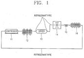
- Figure 1 shows the construction of a refrigerating cycle of a refrigerator in accordance with a conventional art.
- the refrigerating cycle of a conventional refrigerator includes: a compressor 11 for compressing a refrigerant; a condenser 12 for releasing heat of the refrigerant which has been compressed in the compressor 11; a dryer 13 installed at the condenser 12 and removing moisture of the refrigerant; a solenoid valve 14 connected to a refrigerant pipe connected to the dryer 13 and to the refrigerant pipe and controlling opening/closing of the refrigerant pipe; an expansion valve 15 connected to the solenoid valve 14 and reducing a pressure of the refrigerant discharged from the solenoid valve 14; and an evaporator 16 connected to the expansion valve 15 and receiving the decompressed refrigerant to generate cooling air for absorbing heat contained in a food item stored in a refrigerating chamber or a freezing chamber.
- the evaporator 16 is connected to the compressor 11 through the refrigerating pipe.
- the refrigerating cycle of the conventional refrigerator is formed with a flow of the compressor 11 ⁇ the condenser 12 ⁇ dryer 13 ⁇ solenoid valve 14 ⁇ expansion valve 15 ⁇ evaporator 16 ⁇ compressor 11.
- the compressor 11, the condenser 12, the dryer 13, the expansion valve 15, the evaporator 16 and the compressor 11 are connected to each other through the refrigerating pipe.
- a microcomputer (not shown) senses a pre-set temperature of the refrigerating chamber and the freezing chamber of the refrigerator. If the temperature of the refrigerating chamber and the freezing chamber is higher than the pre-set temperature, the microcomputer controls the refrigerating cycle for generating cooling air.
- the compressor 11 compresses an introduced refrigerant under the control of the microcomputer to a high temperature and high pressure refrigerant.
- the refrigerant generated in the compressor 11 is discharged to the condenser 12 through the refrigerant pipe.
- the condenser 12 releases heat of the refrigerant introduced from the compressor 11 and then discharges it to the dryer 13.
- the dryer 13 removes moisture remaining in the refrigerant that has passed through the condenser 12 and discharges the refrigerant to the expansion valve 15 through the solenoid valve 14.
- the expansion valve 15 decompresses the high pressure refrigerant flowing in through the solenoid valve 14 and adjusts the refrigerant flowing at a uniform rate to a state of being easily evaporated and discharges it to the evaporator 16.
- the evaporator 16 receives the refrigerant from the expansion valve 15 and supplies cooling air to the freezing chamber and the refrigerating chamber to absorb heat in the freezing chamber and the refrigerating chamber.
- the compressor employed for the refrigerating cycle of the conventional refrigerator is rotated (operated) only clockwise to constantly generate a maximum output (a maximum freezing capacity). That is, when a temperature in the refrigerator is stable, a maximum output is not required, but since the compressor is rotated only clockwise to constantly generate the maximum output, power consumption of the refrigerator increases.
- one object of the present invention is to provide as method and apparatus for controlling an operation of a refrigerator capable of operating a compressor installed in a refrigerator with optimum efficiency by varying cooling capability of the compressor by controlling a rotation direction of the compressor.
- Another object of the present invention is to provide a method and apparatus for controlling an operation of a compressor of a refrigerator capable of reducing power consumption of the refrigerator and enhancing freezing/refrigerating efficiency of the refrigerator.
- Still another object of the present invention is to provide a method and apparatus for controlling an operation of a refrigerator capable of precisely controlling a temperature of a refrigerator.
- US 4248053 A describes a dual capacity compressor with reversible motor.
- a control system controls the direction of a motor operation or compressor capacity in accordance with temperature conditions, wherein the system comprises timer means delaying a restart of the compressor motor for at least a predetermined time in response to a condition with respect to a change in the operating direction or condition of the compressor when it restarts.
- WO 02/097271 A1 describes a dual capacity compressor having a compressing capacity that can be varied with a required load. If a large capacity is required, a crank shaft of the compressor is rotated in clockwise direction and if a small capacity is required, the crank shaft is rotated in a counterclockwise direction.
- a method and apparatus for controlling an operation of a refrigerator capable of operating a compressor installed in a refrigerator with optimum efficiency by varying a cooling capacity of the compressor by controlling a rotation direction of the compressor, in accordance with preferred embodiments of the present invention will now be described.
- Figure 2 is a flow chart of a method for controlling an operation of a compressor of a refrigerator in accordance with a first example.
- a process of rotating a compressor of the refrigerator counterclockwise and stopping it is repeatedly performed.
- the compressor of the refrigerator is initially rotated clockwise to increase refrigerating capability to quickly lower the temperature inside the refrigerator to a pre-set temperature, and then, the compressor is rotated counterclockwise at every pre-set period in order to maintain the pre-set temperature.
- the compressor is rotated counterclockwise at every pre-set period, the refrigerating capability of the compressor is reduced (step S2).
- the compressor is a TCM (Two Capacity Modulator) compressor.
- step S3 and S4 the temperature inside the refrigerator is sensed by a temperature sensor provided in the refrigerator, and if the temperature inside the refrigerator is identical to a pre-set defrost temperature, a defrosting operation is performed (step S3 and S4).
- step S5 When the defrosting operation is terminated (step S5), the compressor of the refrigerator is rotated clockwise (step S6) to quickly lower the temperature inside the refrigerator that has been raised according to the defrosting operation to the pre-set temperature, and then, the operation of rotating the compressor counterclockwise is repeatedly performed at every pre-set period to maintain the current temperature state inside the refrigerator (step S7).
- the compressor in order to promptly lower the temperature inside the refrigerator that has been raised according to the defrosting operation, the compressor is rotated clockwise to increase the refrigerating capability after termination of the defrosting operation of the refrigerator.
- the compressor is rotated counterclockwise at every pre-set period to maintain the pre-set temperature.
- the compressor when the temperature inside the refrigerator goes high according to the defrosting operation, the compressor is rotated clockwise after the defrosting operation to supply maximum cooling air in the refrigerator, and then, the compressor is rotated counterclockwise at every pre-set period to quickly lower the temperature inside the refrigerator after the defrosting operation, whereby food items can be prevented from spoiling.
- Figure 3 is a flow chart of a method for controlling an operation of a compressor of a refrigerator in accordance with a second example.
- step S11 when an operation mode of a refrigerator is selected by a user (step S11), a rotation direction of a compressor is selected according to the pre-set amount of cooling air supply corresponding to the selected operation mode of the refrigerator and an operation frequency of the compressor is converted according to a temperature inside the refrigerator.
- the amount of cooling air supply in the refrigerator must be maximum.
- the compressor is rotated clockwise, and when a temperature inside the refrigerator is higher than a pre-set standard temperature (e.g., 4°C) in the refrigerator, the operation frequency is increased.
- the amount of cooling air supply must be the minimum.
- the compressor is rotated counterclockwise, and when the temperature inside the refrigerator is equal to or not higher than the pre-set standard temperature, the operation frequency is reduced. Namely, the compressor is rotated clockwise or counterclockwise according to the amount of cooling air supplied to the refrigerator, and at the same time, the rotation speed of each direction of the compressor is controlled based on the varied operation frequency (steps S12-S14). After the rotation direction of the compressor is selected, the rotation speed of the compressor is controlled to supply cooling air into the refrigerator, whereby the temperature inside the refrigerator can be precisely controlled.
- Figure 4 is a block diagram of an apparatus for controlling the operation of the compressor of the refrigerator in accordance with the second example.
- the apparatus for controlling the operation of the compressor of the refrigerator includes: a temperature sensing unit 13 for sensing a temperature inside the refrigerator; a microcomputer 12 for outputting a select signal for selecting a rotation direction of the compressor according to the amount of cooling air supply according to a selected mode when an operation mode of the refrigerator is selected by a user, and outputting an operation control signal for varying an operation frequency of the compressor according to a temperature inside the refrigerator that has been sensed by the temperature sensing unit 13; an operation frequency converting unit 11 for receiving power outputted from a power unit 10 and for converting an operation frequency of the compressor according to the operation control signal; and a clockwise/counterclockwise rotation signal generating unit 14 for controlling the compressor based on the operation frequency that has been converted by the operation frequency converting unit 11 and the select signal.
- the microcomputer 12 applies a select signal (rotation direction select signal) to the clockwise/counterclockwise rotation signal generating unit 14 based on the amount of cooling air supply according to the selected operation mode.
- the microcomputer when maximum cooling capability (maximum amount of cooling air) is required, the microcomputer outputs an operation control signal for maximizing the rotation speed of the compressor to the operation frequency converter 11 and a clockwise select signal for rotating the compressor clockwise to the clockwise/counterclockwise rotation signal generating unit 14.
- the microcomputer 12 outputs an operation control signal for minimizing the rotation speed of the compressor to the operation frequency converting unit 11 and a counterclockwise select signal for rotating the compressor counterclockwise to the clockwise/counterclockwise rotation signal generating unit 14.
- the operation frequency converting unit 11 varies the operation frequency of the compressor in order to vary the rotation speed of the compressor based on the operation control signal and outputs the varied operation frequency to the clockwise/counterclockwise rotation signal generating unit 14.
- the operation frequency converting unit 11 increases the operation frequency of the compressor to maximize the rotation speed of the compressor based on the operation control signal for maximizing the rotation speed of the compressor, and outputs the increased operation frequency to the clockwise/counterclockwise rotation signal generating unit 14.
- the operation frequency converting unit 11 reduces the operation frequency of the compressor to minimize the rotation speed of the compressor based on the operation control signal for minimizing the rotation speed of the compressor, and outputs the reduced operation frequency to the clockwise/counterclockwise rotation signal generating unit 14.
- the clockwise/counterclockwise rotation signal generating unit 14 drives the compressor based on the operation frequency outputted from the operation frequency converting unit 11 and the select signal for selecting the rotation direction of the compressor.
- the clockwise/counterclockwise rotation signal generating unit 14 rotates the compressor clockwise based on the clockwise select signal for rotating the compressor clockwise, and increases the clockwise rotation speed of the compressor based on the increased operation frequency.
- the clockwise/counterclockwise rotation signal generating unit 14 rotates the compressor counterclockwise based on the counterclockwise select signal for rotating the compressor counterclockwise, and reduces the counterclockwise rotation speed of the compressor based on the reduced operation frequency.
- the temperature inside the refrigerator can be precisely controlled.
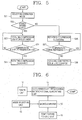
- a method for controlling an operation of a compressor of a refrigerator in accordance with a third example will be described with reference to Figure 5 .
- Figure 5 is a flow chart of a method for controlling an operation of a compressor of a refrigerator in accordance with a third example.
- step S21 when an operation mode of a refrigerator is selected by a user (step S21), it is determined whether the selected operation mode is a power saving operation mode (step S22).
- the compressor is rotated counterclockwise (step S23).
- a pre-set temperature that is, a temperature which has been previously set by a user, for example 4°C, ⁇
- the compressor is rotated clockwise (steps S24 and S25). Namely, when the power saving operation mode is selected by the user, the compressor is driven counterclockwise to reduce power consumption.
- step S26 when a standard operation mode, not the power waving mode, is selected by the user, the compressor is rotated clockwise (step S26). In this case, if the temperature inside the refrigerator becomes lower than a pre-set temperature ( ⁇ ), the compressor is rotated counterclockwise (steps S27 and S28).
- Figure 6 is a block diagram of an apparatus for controlling the operation of the compressor of the refrigerator in accordance with the third example.
- the apparatus for controlling the operation of the compressor of the refrigerator in accordance with the third example includes: a mode selecting unit 15 for selecting a power saving operation mode or a standard operation mode according to a user's request and outputting a mode select signal corresponding to the selected mode; a temperature sensing unit 13 for sensing a temperature inside the refrigerator; a microcomputer 12 for outputting an operation control signal for controlling a rotation direction of the compressor based on the mode select signal and the temperature sense signal of the mode selecting unit 15; and a clockwise/counterclockwise rotation signal generating unit 14 for receiving power outputted from a power unit 10 and for rotating the compressor clockwise or counterclockwise according to the cooperation control signal.
- the mode selecting unit 15 applies a mode select signal corresponding to the power saving operation mode to the microcomputer 12.
- the microcomputer 12 applies an operation control signal for controlling the compressor in a power saving mode to the clockwise/counterclockwise rotation signal generating unit 14 according to the mode select signal outputted from the mode selecting unit 15.
- the clockwise/counterclockwise rotation signal generating unit 14 generates a counterclockwise signal for rotating the compressor counterclockwise according to the operation control signal of the microcomputer 12. Then, the compressor is rotated counterclockwise according to the counterclockwise signal and supplies a small amount of cooling air into the refrigerator. At this time, the temperature sensing unit 12 senses a temperature inside the refrigerator and applies a temperature sense signal corresponding to the sensed temperature to the microcomputer 12.
- the microcomputer 12 compares the sensed temperature with the pre-set temperature ( ⁇ ), and if the sensed temperature is higher than the pre-set temperature ( ⁇ ), the microcomputer 12 applies an operation control signal for rotating the compressor clockwise to the clockwise/counterclockwise rotation signal generating unit 14.
- the clockwise/counterclockwise rotation signal generating unit 14 generates a clockwise signal for rotating the compressor clockwise according to the operation control signal, and the compressor is rotated clockwise by the clockwise signal.
- the compressor While the compressor is being driven clockwise, the temperature inside the refrigerator is sensed, and if the temperature inside the refrigerator is lower than the pre-set temperature (that is, a temperature which has been previously set by a user, for example 6°, ⁇ ), the compressor is rotated counterclockwise.
- the pre-set temperature that is, a temperature which has been previously set by a user, for example 6°, ⁇
- the compressor when the power saving operation mode is selected by the user, the compressor is rotated counterclockwise, and thus, power consumption can be reduced.
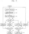
- Figure 7 is a flow chart of a method for controlling an operation of a compressor of a refrigerator in accordance with a fourth example.
- a compressor of the refrigerator is operated (step S31), a temperature inside the refrigerator is sensed (step S32), and then, a rotation direction of the compressor is selected according to the sensed temperature inside the refrigerator (step S33).
- the compressor is rotated clockwise, and if the sensed temperature is lower than the pre-set temperature (e.g., 4°C), the compressor is rotated counterclockwise.
- a pre-set standard temperature e.g. 4°C
- a value of a current applied to the compressor is detected and compared with a pre-set reference current value (steps S34 ⁇ S36). By comparing the value of the current applied to the compressor with the pre-set reference current value, a rotation direction of the compressor can be detected.
- the detected current value is greater than the reference current value (e.g., 0.6A)
- the reference current value e.g. 0.6A
- the detected current value is smaller than the reference current value, it means that there is an error in the rotation direction.
- the compressor is turned off and the process returns to the step S31 of operating the compressor (step S38).
- the detected current value is smaller than the reference current value, it means that there is no error in the rotation direction of the compressor.
- the compressor is rotated counterclockwise, if the detected current value is smaller than the reference current value, the compressor is continuously rotated counterclockwise (step S41).
- the detected current value is greater than the reference current value, it means that there is an error in the rotation direction of the compressor.
- the compressor is rotated counterclockwise, if the detected current value is greater than the reference current value, the compressor is turned off and the process returns to the step S31 of operating the compressor (step S42).
- the compressor when the compressor is operated by determining the rotation direction of the compressor according to the temperature inside the refrigerator or according to the operation mode of the refrigerator, whether or not the compressor is normally operated according to the determined rotation direction is determined according to the value of the current applied to the compressor and the reference current value, whereby the compressor can be normally operated without an error.
- Figure 8 is a block diagram of an apparatus for controlling an operation of a compressor of a refrigerator in accordance with the fourth example.
- the apparatus for controlling the operation of the compressor of the refrigerator in accordance with the fourth example includes: a current detecting unit 16 for detecting a current applied to the compressor (COMP); a temperature sensing unit 13 for sensing a temperature inside a refrigerator; a microcomputer 12 for outputting a compressor operation control signal according to the temperature inside the refrigerator detected by the temperature sensing unit 13, comparing the current value which has been detected by the current detecting unit 16 and a reference current value, and outputting an operation control signal for controlling the compressor; and a clockwise/counterclockwise rotation signal generating unit 14 for generating a clockwise signal or a counterclockwise signal according to the operation control signal of the microcomputer 12 and applying it to the compressor.
- a current detecting unit 16 for detecting a current applied to the compressor (COMP); a temperature sensing unit 13 for sensing a temperature inside a refrigerator; a microcomputer 12 for outputting a compressor operation control signal according to the temperature inside the refrigerator detected by the temperature sensing unit 13, comparing the current value which has been detected by the current
- the microcomputer 12 operates the compressor of the refrigerator. Then, the temperature sensing unit 13 senses a temperature inside the refrigerator and applies a temperature sense signal corresponding to the sensed temperature to the microcomputer 12.
- the microcomputer 12 If the sensed temperature inside the refrigerator is higher than a pre-set standard temperature, the microcomputer 12 outputs an operation control signal for rotating the compressor clockwise to the clockwise/counterclockwise rotation signal generating unit 11. If the sensed temperature inside the refrigerator is lower than the pre-set standard temperature, the microcomputer 12 outputs an operation control signal for rotating the compressor counterclockwise to the clockwise/counterclockwise rotation signal generating unit 11.
- the clockwise/counterclockwise rotation signal generating unit 11 rotates the compressor clockwise or counterclockwise according to the operation control signal of the microcomputer 14. Then, the current detecting unit 16 detects the current applied to the compressor and applies the detected current value to the microcomputer 12.
- the microcomputer 14 detects whether an error occurs in the rotation direction of the compressor by comparing the detected current value with the reference current value, and continuously rotates the compressor in the current rotation direction or turns off the compressor.
- the reference current value is set as 0.6A. For example, when the compressor is actually rotated counterclockwise, the detected current value is smaller than the reference current value. When the compressor is actually rotated clockwise, the detected current value is greater than the reference current value.
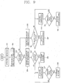
- Figure 9 is a flow chart of a method for controlling an operation of a compressor of a refrigerator in accordance with a fifth example.
- a compressor of the refrigerator is operated and it is sensed whether a current rotation direction of the compressor is clockwise or counterclockwise (steps S51 and S52).
- step S53 and S54 If the current rotation direction of the compressor is clockwise, a temperature inside the refrigerator is sensed (steps S53 and S54), and then, it is determined whether the current rotation direction of the compressor has been selected to be clockwise because the temperature inside the refrigerator is higher than the pre-set temperature (step S55).
- step S55 if the rotation direction of the compressor has been selected clockwise (step S55), the compressor is kept rotating clockwise (step S56).
- step S57 If, however, the rotation direction of the compressor has been selected to be rotated counterclockwise, the operation of the compressor is stopped for a predetermined time (e.g., seven minutes) (step S57), and then, when the predetermined time (seven minutes) elapses (step S58), the compressor is rotated counterclockwise (step S59).
- a predetermined time e.g., seven minutes
- step S53 if the rotation direction of the compressor is counterclockwise, the temperature inside the refrigerator is sensed (step S60) and it is determined whether the current rotation direction of the compressor has been selected counterclockwise because the temperature inside the refrigerator is lower than the pre-set temperature (step S61).
- step S61 If, however, the rotation direction of the compressor has been selected to be clockwise according to the determining result (step S61), the operation of the compressor is stopped for a predetermined time (e.g., seven minutes) (step S63), and then, when the predetermined time (seven minutes) elapses (step S64), the compressor is rotated clockwise (step S65).
- a predetermined time e.g., seven minutes
- the operation of the compressor is stopped for a predetermined time and the rotation direction of the compressor is changed and operated, so that reliability of the compressor can be obtained.
- Figure 10 is a flow chart of a method for controlling an operation of a compressor of a refrigerator in accordance with a sixth embodiment of the present invention.
- step S71 when an operation mode of a refrigerator is selected by a user, a compressor of the refrigerator is operated (step S71) and it is sensed whether the rotation direction of the compressor is clockwise or counterclockwise (step S72).
- step S72 if the rotation direction of the compressor is clockwise (step S73), a first operation range of a temperature sensor of the refrigerator is selected (step S74) and a signal for controlling the operation of the compressor according to the first operation range (step S75).
- the first operation range of the temperature sensor of the refrigerator is approximately set -0.5°C ⁇ +0.5°C according to experimentation.
- the temperature sensor is operated only when and a temperature range of the temperature sensor is -0.5°C ⁇ +0.5°C, and outputs a signal for turning on or off the operation of the compressor
- step S72 if the rotation direction of the compressor is counterclockwise, the second operation range of the temperature sensor of the refrigerator is selected (step S76) and controls the operation of the compressor according to the second operation range (step S77).
- the second operation range of the temperature sensor inside the refrigerator is set approximately -0.3°C ⁇ +0.3°C according to experimentation.
- the temperature sensor is operated only when the temperature range is -0.3°C ⁇ +0.3°C, and outputs a signal for turning on or off the operation of the compressor.
- the operation range of the temperature sensor for sensing the temperature inside the refrigerator is set according to the rotation direction of the compressor and a signal for controlling the operation of the compressor is generated according to the set operation range. Accordingly, when the compressor is rotated clockwise or counterclockwise, the number of times of turning on and off the compressor by a difference of cooling capability according to the rotation direction of the compressor can be improved, and because the temperature difference inside the refrigerator is reduced, power consumption can be reduced.
- Figure 11 is a flow chart of a method for controlling an operation of a compressor of a refrigerator in accordance with a seventh example.
- an operation mode for operating a compressor of a refrigerator counterclockwise is selected by a user and the compressor is rotated counterclockwise (step S81).
- step S83 The temperature of the evaporator itself and the temperature at the entrance of the evaporator are compared, and if the former and the latter are equal (step S83), an amount of refrigerant of a refrigerating cycle is calculated from the equal point (step S84) and set as a refrigerant seal amount of the compressor (step S85).
- Figure 12 is a graph showing the relationship between the seal amount of a refrigerant and the temperature of the evaporator of Figure 11 .
- the amount of a refrigerant when the compressor is rotated counterclockwise is greater than the amount of refrigerant when the compressor is rotated clockwise, so the amount of a refrigerant when the compressor is rotated counterclockwise is set as a refrigerant seal amount of the overall refrigerating cycle of the refrigerator.
- the amount of a refrigerant when the compressor is rotated counterclockwise is set as the refrigerant seal amount of the overall refrigerating cycle, a refrigerant shortage phenomenon, which can occur when the compressor is rotated clockwise or counterclockwise, can be resolved, and thus, freezing efficiency of the refrigerator can be enhanced.
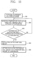
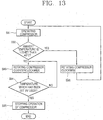
- a method for controlling an operation of a compressor of a refrigerator in accordance with an eighth example will now be described with reference to Figure 13 .
- Figure 13 is a flow chart of a method for controlling an operation of a compressor of a refrigerator in accordance with an eighth example.
- a microcomputer operates a compressor according to the operation mode (step S91).
- an ambient temperature e.g., a temperature at the exterior rear surface of the refrigerator
- a clockwise/counterclockwise rotation signal generating unit rotates the compressor counterclockwise to reduce cooling capability to maintain a pre-set temperature (e.g., 4°C) inside the refrigerator (steps S92 and S93).
- the clockwise/counterclockwise rotation signal generating unit rotates the compressor clockwise to quickly increase cooling capability to maintain the pre-set temperature (e.g., 4°C) inside the refrigerator, and then the process returns to the step S92 (step S96).
- the temperature 43°C is the ambient temperature of the refrigerator for determining a rotation direction of the compressor, and if the ambient temperature of the refrigerator is not lower than 43°C, the compressor is rotated clockwise, and if the ambient temperature of the refrigerator is lower than 43°C, the compressor is rotated counterclockwise.
- step S94 when the temperature inside the refrigerator reaches a temperature previously set by the user (step S94), the operation of the compressor is stopped (step S95). If, however, the temperature inside the temperature does not reach the pre-set temperature, the process returns to the step S93.
- the compressor when the external temperature of the refrigerator is lower than the pre-set external temperature, the compressor is rotated counterclockwise, and if the external temperature of the refrigerator is not lower than the pre-set temperature, the compressor is rotated clockwise.
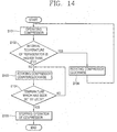
- Figure 14 is a flow chart of a method for controlling an operation of a compressor of a refrigerator in accordance with a ninth example.
- a microcomputer operates a compressor according to the operation mode of the refrigerator (step S101). At this time, if a temperature inside the refrigerator sensed by a temperature sensor is lower than 8°C, a clockwise/counterclockwise rotation signal generating unit rotates the compressor counterclockwise to reduce cooling capability to maintain a pre-set temperature inside the refrigerator (steps S102 and S103).
- the clockwise/counterclockwise rotation signal generating unit rotates the compressor clockwise to quickly increase cooling capability to maintain the pre-set temperature (e.g., 4°C) inside the refrigerator, and then, the process returns to the step S102 (step S106).
- the temperature 8°C is an internal temperature of the refrigerator for determining a rotation direction of the compressor, and when the internal temperature of the refrigerator is not lower than 8°C, the compressor is rotated clockwise, and if the internal temperature of the refrigerator is lower than 8°C, the compressor is rotated counterclockwise.
- step S104 when the temperature inside the refrigerator reaches a temperature previously set by the user (step S104), the operation of the compressor is stopped (step S105). If, however, the temperature inside the temperature does not reach the pre-set temperature, the process returns to the step S103.
- the compressor when the internal temperature of the refrigerator is lower than the pre-set internal temperature (8°C), the compressor is rotate clockwise, whereby power consumption can be minimized and the temperature inside the refrigerator can be precisely controlled to the temperature set by the user.
- Figure 15 is a flow chart of a method for controlling an operation of a compressor of a refrigerator in accordance with a tenth example.
- a door sensor determines whether the refrigerator door is properly closed (step S111).
- a door open alarm sound is generated when a predetermined time (e.g., 1-2 minutes) elapses (step S120).
- a predetermined time e.g., 1-2 minutes
- a first temperature inside the refrigerator is sensed (step S112).
- step S113 After the first temperature inside the refrigerator is sensed, it is determined whether a predetermined time (e.g., 5 minutes) has elapsed (step S113).
- a predetermined time e.g., 5 minutes
- a second temperature inside the refrigerator is sensed (step S114).
- the second temperature means a temperature inside the refrigerator with the lapse of the predetermined time after the first temperature is checked.
- step S115 it is determined whether a difference between the first and second temperatures is the same as or greater than a pre-set reference temperature (e.g., 3°C) (step S115).
- a pre-set reference temperature e.g., 3°C
- the compressor is rotated clockwise to supply maximum cooling air into the refrigerator to quickly lower the temperature inside the refrigerator to an internal temperature of the refrigerator previously set by the user (step S119).
- the compressor is rotated counterclockwise at every pre-set period to maintain the internal temperature of the refrigerator previously set by the user (step S116).
- the operation of the compressor is stopped. If, however, the temperature inside the refrigerator and the internal temperature of the refrigerator previously set by the user are not identical, the compressor is rotated clockwise to supply the maximum cooling air into the refrigerator to quickly lower the temperature inside the refrigerator to an internal temperature of the refrigerator previously set by the user, and then, when the temperature inside the refrigerator and the internal temperature of the refrigerator previously set by the user are identical, the operation of the compressor is stopped (steps S117 and S118).
- the first temperature inside the refrigerator is sensed simultaneously when the refrigerator door is sensed, and when a predetermined time elapses, the second temperature is sensed. Thereafter, when the difference between the first and second temperatures is the same or greater than a certain temperature (+3°C), the compressor is rotated clockwise to supply maximum cooling air into the refrigerator to cope with a change of load, so that an optimum temperature state can be maintained.
- Figure 16 is a flow chart of a method for controlling an operation of a compressor of a refrigerator in accordance with an eleventh example.
- a compressor inside a refrigerator is rotated clockwise or counterclockwise to maintain a temperature previously set by a user inside the refrigerator (step S131). It is sensed whether power supplied to the refrigerator is cut off due to a power failure in real time (step S132).
- step S133 When power supply into the refrigerator is cut off, it is determined whether power is re-supplied to the refrigerator within a predetermined time (7 minutes ⁇ 100 minutes) (step S133). For example, when power supply to the refrigerator is cut off due to a power failure, it is determined whether the power cut-off time period is the same or greater than, or lower than the predetermined time (7 minutes ⁇ 100 minutes).
- a compressor is rotated clockwise (step S137), and then, the compressor is rotated clockwise according to a temperature inside the temperature (step S138).
- power supply to the refrigerator is cut off due to a power failure, and if the cut-off time exceeds 100 minutes, the compressor is rotated clockwise to supply maximum cooling air into the refrigerator, and then, when the temperature inside the refrigerator reaches a temperature previously set by the user, the compressor is rotated counterclockwise.
- the compressor is rotated in the same rotation direction of the compressor as the direction before the power was cut off (step S134).
- the predetermined time is preferably set within 7 minutes-100 minutes.
- step S135 it is determined whether the temperature inside the refrigerator is identical to the temperature previously set by the user.
- step S136 the operation of the compressor is stopped.
- the compressor is rotated clockwise and then counterclockwise to maintain the temperature previously set by the user inside the refrigerator (steps S137 and S138).
- the compressor when power supplied to the refrigerator is cut off more than a predetermined time and then re-supplied, the compressor is rotated clockwise to supply maximum cooling air into the refrigerator. Or, when power supplied to the refrigerator is cut off within the predetermined time period and then re-supplied, the compressor is rotated in the same direction as the direction before the power is cut off to supply cooling air into the refrigerator. Thus, it can quickly cope with a change of the load of the refrigerator.
- Figure 17 is a flow chart of a method for controlling an operation of a compressor of a refrigerator in accordance with a twelfth example.
- a compressor in order to maintain a pre-set temperature inside a refrigerator, a compressor is rotated clockwise to quickly lower an initial temperature inside the refrigerator to the pre-set temperature and then the compressor is rotated counterclockwise to maintain the pre-set temperature (step S141).
- the rotation direction of the compressor is determined by a rotation direction select signal. Whether or not the rotation direction of the compressor rotated by the rotation direction select signal and an actual rotation direction of the compressor are identical can be known through a sensor for sensing a rotation direction of the compressor.
- Figures 18A and 18B show a sensor for sensing a rotation direction of a compressor rotated clockwise or counterclockwise in accordance with the twelfth example.
- the rotation direction of the compressor rotating clockwise according to the select signal outputted from a clockwise/counterclockwise rotation signal generating unit is sensed by a first rotation direction sensor (A) and a second rotation direction sensor (B).
- the first and second rotation direction sensors installed at the compressor approach each other. Then, the first rotation direction sensor outputs a clockwise sense signal, and a microcomputer recognizes that the rotation direction of the compressor is clockwise based on the clockwise sense signal of the first rotation direction sensor.
- the rotation direction of the compressor rotating counterclockwise according to a rotation direction (counterclockwise) select signal outputted from the clockwise/counterclockwise rotation signal generating unit is sensed by the first rotation direction sensor (A) and a third rotation direction sensor (C).
- the first and third rotation direction sensors installed at the compressor approach each other. Then, the first rotation direction sensor outputs a counterclockwise sense signal, and the microcomputer recognizes that the rotation direction of the compressor is counterclockwise based on the counterclockwise sense signal of the first rotation direction sensor.
- step S143 the compressor is rotated according to the rotation direction select signal.
- the actual rotation direction of the compressor is sensed by rotation direction sensors installed at the compressor.
- step S144 If, however, the rotation direction corresponding to the rotation direction select signal for rotating the compressor 30 is not identical to the actual rotation direction of the compressor 30, the compressor is rotated according to the rotation direction select signal until the temperature inside the refrigerator reaches the temperature previously set by the user (step S144).
- the compressor When the temperature inside the refrigerator reaches the temperature previously set by the user, the compressor is rotated once in a direction opposite to the rotation direction corresponding to the rotation direction select signal of the compressor 30. Namely, by rotating once the compressor in the direction opposite to the rotation direction corresponding to the rotation direction select signal of the compressor 30, an erroneous coupling state of each part of the compressor can be released (step S145).
- the compressor is rotated clockwise or counterclockwise according to the temperature sensed by the temperature sensor in the refrigerator.
- Figure 19 is a flow chart of a method for controlling an operation of a compressor of a refrigerator in accordance with an embodiment of the present invention.
- a compressor of the refrigerator is initially rotated clockwise to increase cooling capability to quickly lower the temperature inside the refrigerator, and then, it is determined whether a pre-set time (e.g., 10 minutes) has elapsed (steps S151 and S152).
- a pre-set time e.g. 10 minutes
- the cooling capability is increased by rotating the compressor clockwise for the pre-set time, the temperature inside the refrigerator quickly reaches near the temperature previously set by the user.
- the compressor of the refrigerator is rotated counterclockwise to make the temperature inside the refrigerator reach the pre-set temperature. Namely, after the temperature inside the refrigerator quickly reaches near the pre-set temperature by rotating the compressor clockwise during the pre-set time, the compressor is rotated counterclockwise to make the temperature inside the refrigerator gradually reach the temperature previously set by the user, thereby reducing power consumption of the compressor (step S153).
- the pre-set time elapses, maximum cooling capability is not needed, so it is not necessary to waste power by rotating the compressor clockwise after the pre-set time.
- step S154 it is determined whether the temperature inside the refrigerator reaches the temperature previously set by the user. If the temperature inside the refrigerator reaches the temperature previously set by the user, the operation of the compressor rotating counterclockwise is stopped (step S155).
- the compressor is rotated counterclockwise at every predetermined period until the temperature inside the refrigerator reaches the temperature previously set by the user.
- the operation of the compressor is stopped. If the temperature inside the refrigerator is not identical to the temperature previously set by the user, the process of rotating the compressor counterclockwise at every certain period is repeatedly performed.
- the compressor of the refrigerator is rotated clockwise for the pre-set time to make the temperature inside the refrigerator quickly reach near the temperature previously set by the user, and then, when the pre-set time elapses, the compressor is rotated counterclockwise to make the temperature inside the refrigerator gradually reach the temperature previously set by the user, thereby reducing power consumption of the compressor.
- the method and apparatus for controlling an operation of a compressor of a refrigerator in accordance with the present invention have many advantages.
- the compressor when the temperature inside the refrigerator goes high according to the defrosting operation, the compressor is rotated clockwise after the defrosting operation to supply maximum cooling air in the refrigerator, and then, the compressor is rotated counterclockwise at every pre-set period to quickly lower the temperature inside the refrigerator after the defrosting operation, whereby food items can be prevented from spoiling.
- the temperature inside the refrigerator can be precisely controlled.
- the compressor when the power saving operation mode is selected by the user, the compressor is rotated counterclockwise, and thus, power consumption can be reduced.
- the operation of the compressor is stopped for a predetermined time and the rotation direction of the compressor is changed and operated, so that reliability of the compressor can be obtained.
- the operation range of the temperature sensor for sensing the temperature inside the refrigerator is set according to the rotation direction of the compressor and a signal for controlling the operation of the compressor is generated according to the set operation range. Accordingly, when the compressor is rotated clockwise or counterclockwise, the number of times of turning on and off the compressor by a difference of cooling capability according to the rotation direction of the compressor can be improved, and because the temperature difference inside the refrigerator is reduced, power consumption can be reduced.
- the amount of a refrigerant when the compressor is rotated counterclockwise is set as the refrigerant seal amount of the overall refrigerating cycle, a refrigerant shortage phenomenon, which can occur when the compressor is rotated clockwise or counterclockwise, can be resolved, and thus, freezing efficiency of the refrigerator can be enhanced.
- the compressor when the external temperature of the refrigerator is lower than the pre-set external temperature, the compressor is rotated counterclockwise, and if the external temperature of the refrigerator is not lower than the pre-set temperature, the compressor is rotated clockwise.
- the compressor when the internal temperature of the refrigerator is lower than the pre-set internal temperature (8°C), the compressor is rotate clockwise, whereby power consumption can be minimized and the temperature inside the refrigerator can be precisely controlled to the temperature set by the user.
- the first temperature inside the refrigerator is sensed simultaneously when the refrigerator door is sensed, and when a predetermined time elapses, the second temperature is sensed. Thereafter, when the difference between the first and second temperatures is the same or greater than a certain temperature (+3°C), the compressor is rotated clockwise to supply maximum cooling air into the refrigerator to cope with a change of load, so that an optimum temperature state can be maintained.
- the compressor when power supplied to the refrigerator is cut off more than a predetermined time and then re-supplied, the compressor is rotated clockwise to supply maximum cooling air into the refrigerator. Or, when power supplied to the refrigerator is cut off within the predetermined time period and then re-supplied, the compressor is rotated in the same direction as the direction before the power is cut off to supply cooling air into the refrigerator. Thus, it can quickly cope with a change of the load of the refrigerator.
- the compressor of the refrigerator is rotated clockwise for the pre-set time to make the temperature inside the refrigerator quickly reach near the temperature previously set by the user, and then, when the pre-set time elapses, the compressor is rotated counterclockwise to make the temperature inside the refrigerator gradually reach the temperature previously set by the user, thereby reducing power consumption of the compressor.
Landscapes
- Engineering & Computer Science (AREA)
- Mechanical Engineering (AREA)
- General Engineering & Computer Science (AREA)
- Physics & Mathematics (AREA)
- Thermal Sciences (AREA)
- Chemical & Material Sciences (AREA)
- Combustion & Propulsion (AREA)
- Devices That Are Associated With Refrigeration Equipment (AREA)
- Control Of Positive-Displacement Pumps (AREA)
Claims (11)
- Procédé de commande d'un fonctionnement d'un compresseur d'un réfrigérateur comprenant :- faire varier une capacité de refroidissement d'un compresseur installé dans un réfrigérateur en commandant un sens de rotation du compresseur en fonction d'une condition de charge du réfrigérateur, dans lequel la capacité de refroidissement du compresseur augmente lorsque le compresseur est tourné dans le sens des aiguilles d'une montre et diminue lorsque le compresseur est tourné dans le sens inverse des aiguilles d'une montre,
caractérisé en ce que l'étape de la commande du sens de rotation du compresseur comprend :- une étape (S151) à laquelle le compresseur du réfrigérateur est tourné dans le sens des aiguilles d'une montre au cours d'un temps préréglé ; et- une étape (S152, S153) à laquelle, à l'expiration du temps préréglé, le compresseur est tourné dans le sens inverse des aiguilles d'une montre. - Procédé selon la revendication 1, dans lequel le temps préréglé est un temps au cours duquel la température à l'intérieur du réfrigérateur atteint presque la température réglée par l'utilisateur (S154).
- Procédé selon la revendication 2, comprenant en outre : une étape à laquelle, lorsque le compresseur est tourné dans le sens inverse des aiguilles d'une montre (S153) et la température à l'intérieur du réfrigérateur atteint la température réglée par l'utilisateur (S154), le fonctionnement du compresseur est arrêté (S155).
- Procédé selon la revendication 3, dans lequel, si la température à l'intérieur du réfrigérateur n'atteint pas la température réglée par l'utilisateur, le compresseur est tourné dans le sens inverse des aiguilles d'une montre à chaque période préréglée.
- Appareil de commande d'un fonctionnement d'un compresseur d'un réfrigérateur comprenant :- un micro-ordinateur (12) pour délivrer un signal de sélection pour sélectionner un sens de rotation d'un compresseur en fonction d'un mode de fonctionnement d'un réfrigérateur lorsque le mode de fonctionnement du réfrigérateur est sélectionné par un utilisateur ;
caractérisé en ce que l'appareil comprend en outre :- un convertisseur de fréquence de fonctionnement (11) pour convertir une fréquence de fonctionnement d'un compresseur en fonction d'une température dans le réfrigérateur ; et- une unité de génération de signal de rotation dans le sens des aiguilles d'une montre/dans le sens inverse des aiguilles d'une montre (14) pour sélectionner un sens de rotation du compresseur en fonction du signal de sélection et pour faire varier une vitesse de rotation du sens de rotation du compresseur en fonction de la fréquence de fonctionnement convertie,dans lequel le compresseur est tourné dans le sens des aiguilles d'une montre au cours d'un temps préréglé et, à l'expiration du temps préréglé, le compresseur est tourné dans le sens inverse des aiguilles d'une montre. - Appareil selon la revendication 5, comprenant en outre : un capteur de température (13) pour détecter la température à l'intérieur du réfrigérateur, dans lequel une plage de fonctionnement du capteur de température (13) est réglée en fonction du sens de rotation du compresseur et le capteur de température (13) détecte la température à l'intérieur du réfrigérateur en fonction de la plage de fonctionnement réglée.
- Appareil selon la revendication 6, dans lequel, lorsque le compresseur est tourné dans le sens des aiguilles d'une montre, la plage de fonctionnement du capteur de température (13) est de -0,5 °C à +0,5 °C.
- Appareil selon la revendication 6, dans lequel, lorsque le compresseur est tourné dans le sens inverse des aiguilles d'une montre, la plage de fonctionnement du capteur de température (13) est de -0,3 °C à +0,3 °C.
- Appareil selon la revendication 5, comprenant en outre :- une unité de sélection de mode (15) pour délivrer un signal de sélection de mode correspondant à un mode de fonctionnement sélectionné du réfrigérateur lorsque le mode de fonctionnement sélectionné par l'utilisateur est un mode de fonctionnement à économie d'énergie ou un mode de fonctionnement normal,dans lequel, lorsque le mode de fonctionnement du réfrigérateur est le mode de fonctionnement à économie d'énergie, l'unité de génération de signal de rotation dans le sens des aiguilles d'une montre/dans le sens inverse des aiguilles d'une montre (14) fait tourner le compresseur dans le sens inverse des aiguilles d'une montre puis, lorsque la température à l'intérieur du réfrigérateur est supérieure à une température préréglée, l'unité de génération de signal de rotation dans le sens des aiguilles d'une montre/dans le sens inverse des aiguilles d'une montre (14) fait tourner le compresseur dans le sens des aiguilles d'une montre ; et
lorsque le mode de fonctionnement du réfrigérateur est le mode de fonctionnement normal, l'unité de génération de signal de rotation dans le sens des aiguilles d'une montre/dans le sens inverse des aiguilles d'une montre (14) fait tourner le compresseur dans le sens des aiguilles d'une montre puis, lorsque la température à l'intérieur du réfrigérateur atteint la température préréglée, l'unité de génération de signal de rotation dans le sens des aiguilles d'une montre/dans le sens inverse des aiguilles d'une montre (14) fait tourner le compresseur dans le sens inverse des aiguilles d'une montre. - Appareil selon la revendication 9, comprenant en outre :- une unité de détection de courant (16) pour détecter un courant appliqué au compresseur,dans lequel, lorsque le compresseur est tourné dans le sens des aiguilles d'une montre en fonction du mode de fonctionnement du réfrigérateur, si la valeur de courant détecté est supérieure à une valeur de courant de référence préréglée, le micro-ordinateur (12) délivre un signal de commande de fonctionnement pour faire tourner continuellement le compresseur dans le sens des aiguilles d'une montre et, si la valeur de courant détecté est inférieure à la valeur de courant de référence, le micro-ordinateur (12) délivre un signal de commande de fonctionnement pour arrêter le compresseur.
- Appareil selon la revendication 10, dans lequel, lorsque le compresseur est tourné dans le sens inverse des aiguilles d'une montre en fonction du mode de fonctionnement du réfrigérateur, si la valeur de courant détecté est supérieure à une valeur de courant de référence préréglée, le micro-ordinateur (12) délivre un signal de commande de fonctionnement pour arrêter le compresseur et, si la valeur de courant détecté est inférieure à la valeur de courant de référence, le micro-ordinateur (12) délivre un signal de commande de fonctionnement pour faire tourner continuellement le compresseur dans le sens inverse des aiguilles d'une montre.
Applications Claiming Priority (1)
| Application Number | Priority Date | Filing Date | Title |
|---|---|---|---|
| PCT/KR2003/002296 WO2005047700A1 (fr) | 2003-10-29 | 2003-10-29 | Procede et appareil de commande de compresseur pour refrigerateur et appareil |
Publications (3)
| Publication Number | Publication Date |
|---|---|
| EP1687536A1 EP1687536A1 (fr) | 2006-08-09 |
| EP1687536A4 EP1687536A4 (fr) | 2011-09-07 |
| EP1687536B1 true EP1687536B1 (fr) | 2016-02-17 |
Family
ID=34587756
Family Applications (1)
| Application Number | Title | Priority Date | Filing Date |
|---|---|---|---|
| EP03759029.6A Expired - Lifetime EP1687536B1 (fr) | 2003-10-29 | 2003-10-29 | Procédé et appareil de commande de compresseur pour réfrigérateur |
Country Status (5)
| Country | Link |
|---|---|
| US (1) | US7984617B2 (fr) |
| EP (1) | EP1687536B1 (fr) |
| JP (1) | JP4331725B2 (fr) |
| AU (1) | AU2003274777B2 (fr) |
| WO (1) | WO2005047700A1 (fr) |
Families Citing this family (15)
| Publication number | Priority date | Publication date | Assignee | Title |
|---|---|---|---|---|
| US10464579B2 (en) | 2006-04-17 | 2019-11-05 | Ge Global Sourcing Llc | System and method for automated establishment of a vehicle consist |
| US10338580B2 (en) | 2014-10-22 | 2019-07-02 | Ge Global Sourcing Llc | System and method for determining vehicle orientation in a vehicle consist |
| US7793509B2 (en) | 2004-04-12 | 2010-09-14 | Johnson Controls Technology Company | System and method for capacity control in a multiple compressor chiller system |
| JP2009515130A (ja) * | 2005-11-03 | 2009-04-09 | ジョンソン コントロールズ テクノロジー カンパニー | 多重圧縮機冷却器システムでの能力制御のためのシステムおよび方法 |
| JP5084794B2 (ja) * | 2009-07-22 | 2012-11-28 | 住友重機械工業株式会社 | クライオポンプ、及びクライオポンプの監視方法 |
| US8291718B2 (en) * | 2010-09-02 | 2012-10-23 | General Electric Company | DSM defrost during high demand |
| US9897082B2 (en) | 2011-09-15 | 2018-02-20 | General Electric Company | Air compressor prognostic system |
| DE102012102041B4 (de) * | 2012-03-09 | 2019-04-18 | Audi Ag | Vorrichtung und Verfahren zur Vereisungsvermeidungsregelung für Wärmepumpenverdampfer |
| US9562715B2 (en) * | 2012-03-21 | 2017-02-07 | Thermo King Corporation | Power regulation system for a mobile environment-controlled unit and method of controlling the same |
| US20130280095A1 (en) | 2012-04-20 | 2013-10-24 | General Electric Company | Method and system for reciprocating compressor starting |
| US9010133B2 (en) * | 2012-06-20 | 2015-04-21 | Whirlpool Corporation | On-line energy consumption optimization adaptive to environmental condition |
| CN105258445B (zh) * | 2015-11-05 | 2018-02-02 | 青岛海尔股份有限公司 | 采用变频压缩机的冰箱控制方法及控制系统 |
| KR102349193B1 (ko) * | 2017-07-05 | 2022-01-11 | 엘지전자 주식회사 | 냉장고의 제어방법 |
| CN112019030B (zh) * | 2019-05-31 | 2021-11-19 | 广东美的制冷设备有限公司 | 运行控制方法、装置、电路、家电设备和计算机存储介质 |
| EP4433764A1 (fr) * | 2021-11-15 | 2024-09-25 | Maersk Container Industry A/S | Système de réfrigération et procédé de détermination d'un état de charge de fluide frigorigène à l'intérieur de celui-ci |
Family Cites Families (40)
| Publication number | Priority date | Publication date | Assignee | Title |
|---|---|---|---|---|
| US2257478A (en) * | 1938-10-22 | 1941-09-30 | Honeywell Regulator Co | Air conditioning system |
| US3059448A (en) * | 1958-05-01 | 1962-10-23 | Carrier Corp | Air conditioning apparatus |
| US3503222A (en) * | 1968-10-16 | 1970-03-31 | Ice Ind Intern Inc | Bin actuated stop motion for ice making machines |
| US4044362A (en) * | 1976-03-04 | 1977-08-23 | Greenhut Bart E | Data recording instrument |
| US4151725A (en) * | 1977-05-09 | 1979-05-01 | Borg-Warner Corporation | Control system for regulating large capacity rotating machinery |
| US4245966A (en) * | 1978-01-30 | 1981-01-20 | Westinghouse Electric Corp. | Reciprocating piston device with changeable stroke length |
| US4326874A (en) * | 1978-03-13 | 1982-04-27 | Buerklin Werner | Process and apparatus for preparing compostable material |
| US4228846A (en) * | 1978-08-02 | 1980-10-21 | Carrier Corporation | Control apparatus for a two-speed heat pump |
| US4236874A (en) | 1979-03-02 | 1980-12-02 | Westinghouse Electric Corp. | Dual capacity compressor with reversible motor and controls arrangement therefor |
| US4248053A (en) * | 1979-03-05 | 1981-02-03 | Westinghouse Electric Corp. | Dual capacity compressor with reversible motor and controls arrangement therefor |
| US4689967A (en) * | 1985-11-21 | 1987-09-01 | American Standard Inc. | Control and method for modulating the capacity of a temperature conditioning system |
| JPS5991501A (ja) * | 1982-11-18 | 1984-05-26 | Nittan Co Ltd | 温度検出器 |
| US4598559A (en) * | 1985-05-31 | 1986-07-08 | Carrier Corporation | Reversible fixed vane rotary compressor having a reversing disk which carries the suction port |
| JPH07112335B2 (ja) * | 1986-07-11 | 1995-11-29 | 株式会社豊田自動織機製作所 | 圧縮機における回転検出装置 |
| JPS6370421U (fr) * | 1986-10-29 | 1988-05-11 | ||
| US4927594A (en) * | 1988-08-10 | 1990-05-22 | Westinghouse Electric Corp. | Thermocouple based control rod position indication system |
| US4903502A (en) * | 1988-08-26 | 1990-02-27 | Thermo King Corporation | Rate of change temperature control for transport refrigeration systems |
| US5200872A (en) * | 1989-12-08 | 1993-04-06 | Texas Instruments Incorporated | Internal protection circuit for electrically driven device |
| US5285646A (en) * | 1990-06-01 | 1994-02-15 | Samsung Electronics Co., Ltd. | Method for reversing a compressor in a heat pump |
| KR940002232B1 (ko) * | 1991-04-01 | 1994-03-19 | 삼성전자 주식회사 | 냉장고의 복수온도조절장치 |
| JP2699724B2 (ja) * | 1991-11-12 | 1998-01-19 | 松下電器産業株式会社 | 2段気体圧縮機 |
| KR100220390B1 (ko) | 1997-06-18 | 1999-09-15 | 구자홍 | 압축기의 가변속도 제어방법 및 장치 |
| US6092993A (en) * | 1997-08-14 | 2000-07-25 | Bristol Compressors, Inc. | Adjustable crankpin throw structure having improved throw stabilizing means |
| RU2151326C1 (ru) | 1997-11-20 | 2000-06-20 | ЗАО ППТФ "Элма-Ко" | Герметичный компрессор с регулируемой холодопроизводительностью |
| US6099259A (en) * | 1998-01-26 | 2000-08-08 | Bristol Compressors, Inc. | Variable capacity compressor |
| US7083397B1 (en) * | 1998-06-04 | 2006-08-01 | Scroll Technologies | Scroll compressor with motor control for capacity modulation |
| US6272872B1 (en) * | 1999-12-21 | 2001-08-14 | Kent B. Herrick | Motor reversal switching system |
| JP3799921B2 (ja) * | 1999-12-24 | 2006-07-19 | 株式会社豊田自動織機 | 容量可変型圧縮機の制御装置 |
| JP2001193662A (ja) * | 2000-01-07 | 2001-07-17 | Toyota Autom Loom Works Ltd | 容量可変型圧縮機の制御装置 |
| JP2002266772A (ja) | 2001-03-07 | 2002-09-18 | Matsushita Electric Ind Co Ltd | 密閉型電動圧縮機 |
| ATE408758T1 (de) * | 2001-06-01 | 2008-10-15 | Lg Electronics Inc | Verdichter mit doppelter leistung |
| JP2003042627A (ja) | 2001-07-25 | 2003-02-13 | Hitachi Ltd | 冷蔵庫 |
| KR100459167B1 (ko) | 2001-09-12 | 2004-12-03 | 엘지전자 주식회사 | 압축기용 모터의 제어장치 |
| JP2002162151A (ja) | 2001-09-19 | 2002-06-07 | Sanyo Electric Co Ltd | 冷蔵庫 |
| US6609896B2 (en) * | 2002-01-28 | 2003-08-26 | Bristol Compressors, Inc. | Device and method for reducing forces in mechanisms |
| US20040241010A1 (en) * | 2003-03-27 | 2004-12-02 | Samsung Electronics Co., Ltd. | Variable capacity rotary compressor |
| US8540493B2 (en) * | 2003-12-08 | 2013-09-24 | Sta-Rite Industries, Llc | Pump control system and method |
| US7562536B2 (en) * | 2005-03-02 | 2009-07-21 | York International Corporation | Method and apparatus to sense and control compressor operation in an HVAC system |
| KR20090020019A (ko) * | 2007-08-22 | 2009-02-26 | 엘지전자 주식회사 | 냉장고의 제어방법 |
| KR100964368B1 (ko) * | 2007-10-31 | 2010-06-17 | 엘지전자 주식회사 | 공기조화기의 전동기 제어방법 및 그 제어 장치 |
-
2003
- 2003-10-29 JP JP2005510582A patent/JP4331725B2/ja not_active Expired - Fee Related
- 2003-10-29 WO PCT/KR2003/002296 patent/WO2005047700A1/fr not_active Ceased
- 2003-10-29 EP EP03759029.6A patent/EP1687536B1/fr not_active Expired - Lifetime
- 2003-10-29 AU AU2003274777A patent/AU2003274777B2/en not_active Ceased
- 2003-10-29 US US10/577,429 patent/US7984617B2/en not_active Expired - Fee Related
Also Published As
| Publication number | Publication date |
|---|---|
| JP4331725B2 (ja) | 2009-09-16 |
| EP1687536A4 (fr) | 2011-09-07 |
| US7984617B2 (en) | 2011-07-26 |
| WO2005047700A1 (fr) | 2005-05-26 |
| EP1687536A1 (fr) | 2006-08-09 |
| AU2003274777B2 (en) | 2010-06-03 |
| AU2003274777A1 (en) | 2004-06-06 |
| AU2003274777A8 (en) | 2005-06-06 |
| US20070068181A1 (en) | 2007-03-29 |
| JP2007520680A (ja) | 2007-07-26 |
Similar Documents
| Publication | Publication Date | Title |
|---|---|---|
| EP1687536B1 (fr) | Procédé et appareil de commande de compresseur pour réfrigérateur | |
| US6438978B1 (en) | Refrigeration system | |
| US11867448B2 (en) | Refrigerator and method for controlling the same | |
| US12209797B2 (en) | Refrigerator and method for controlling refrigerator | |
| US8037700B2 (en) | Air conditioning system for low ambient cooling | |
| EP3764033A1 (fr) | Réfrigérateur et son procédé de commande | |
| KR102659139B1 (ko) | 냉장고 및 그의 제어방법 | |
| US11940200B2 (en) | Refrigerator and control method of refrigerator | |
| JP2002156177A (ja) | 冷蔵庫の冷却サイクル制御装置及びその制御方法 | |
| CN114779858A (zh) | 样本分析装置的启动方法、装置、设备及存储介质 | |
| KR20190005033A (ko) | 냉장고의 제어방법 | |
| US6889511B2 (en) | Temperature control device for refrigerating apparatus and method thereof | |
| MXPA06004888A (en) | Method of controlling compressor for refrigerator and apparatus thereof | |
| RU2329440C2 (ru) | Способ управления компрессором холодильника и устройство для осуществления способа | |
| JP2002195668A (ja) | 冷蔵庫 | |
| KR100389392B1 (ko) | 냉장고의 소음절감운전방법 | |
| KR100397558B1 (ko) | 냉장고 고내 온도 제어 방법 | |
| US12169089B2 (en) | Refrigerator and method of controlling the same | |
| KR20040039628A (ko) | 냉장고의 제어방법 | |
| KR20020072711A (ko) | 냉장고의 제상제어방법 | |
| KR19990041827A (ko) | 냉장고 및 그 제어방법 | |
| KR20040018704A (ko) | 냉장고의 정/역회전 압축기 운전제어방법 |
Legal Events
| Date | Code | Title | Description |
|---|---|---|---|
| PUAI | Public reference made under article 153(3) epc to a published international application that has entered the european phase |
Free format text: ORIGINAL CODE: 0009012 |
|
| 17P | Request for examination filed |
Effective date: 20060503 |
|
| AK | Designated contracting states |
Kind code of ref document: A1 Designated state(s): DE GB IT |
|
| DAX | Request for extension of the european patent (deleted) | ||
| RBV | Designated contracting states (corrected) |
Designated state(s): DE GB IT |
|
| A4 | Supplementary search report drawn up and despatched |
Effective date: 20110809 |
|
| RIC1 | Information provided on ipc code assigned before grant |
Ipc: F04B 49/20 20060101ALI20110803BHEP Ipc: F04B 49/12 20060101ALI20110803BHEP Ipc: F04B 49/00 20060101AFI20110803BHEP |
|
| 17Q | First examination report despatched |
Effective date: 20120209 |
|
| GRAP | Despatch of communication of intention to grant a patent |
Free format text: ORIGINAL CODE: EPIDOSNIGR1 |
|
| INTG | Intention to grant announced |
Effective date: 20150903 |
|
| RAP1 | Party data changed (applicant data changed or rights of an application transferred) |
Owner name: LG ELECTRONICS INC. |
|
| GRAS | Grant fee paid |
Free format text: ORIGINAL CODE: EPIDOSNIGR3 |
|
| GRAA | (expected) grant |
Free format text: ORIGINAL CODE: 0009210 |
|
| AK | Designated contracting states |
Kind code of ref document: B1 Designated state(s): DE GB IT |
|
| REG | Reference to a national code |
Ref country code: GB Ref legal event code: FG4D |
|
| REG | Reference to a national code |
Ref country code: DE Ref legal event code: R096 Ref document number: 60348554 Country of ref document: DE |
|
| REG | Reference to a national code |
Ref country code: DE Ref legal event code: R097 Ref document number: 60348554 Country of ref document: DE |
|
| PLBE | No opposition filed within time limit |
Free format text: ORIGINAL CODE: 0009261 |
|
| STAA | Information on the status of an ep patent application or granted ep patent |
Free format text: STATUS: NO OPPOSITION FILED WITHIN TIME LIMIT |
|
| 26N | No opposition filed |
Effective date: 20161118 |
|
| REG | Reference to a national code |
Ref country code: DE Ref legal event code: R119 Ref document number: 60348554 Country of ref document: DE |
|
| GBPC | Gb: european patent ceased through non-payment of renewal fee |
Effective date: 20161029 |
|
| PG25 | Lapsed in a contracting state [announced via postgrant information from national office to epo] |
Ref country code: DE Free format text: LAPSE BECAUSE OF NON-PAYMENT OF DUE FEES Effective date: 20170503 Ref country code: GB Free format text: LAPSE BECAUSE OF NON-PAYMENT OF DUE FEES Effective date: 20161029 |
|
| PG25 | Lapsed in a contracting state [announced via postgrant information from national office to epo] |
Ref country code: IT Free format text: LAPSE BECAUSE OF NON-PAYMENT OF DUE FEES Effective date: 20161029 |