EP1688193A1 - Biegevorrichtung mit kompakter Biegearm - Google Patents
Biegevorrichtung mit kompakter Biegearm Download PDFInfo
- Publication number
- EP1688193A1 EP1688193A1 EP06425056A EP06425056A EP1688193A1 EP 1688193 A1 EP1688193 A1 EP 1688193A1 EP 06425056 A EP06425056 A EP 06425056A EP 06425056 A EP06425056 A EP 06425056A EP 1688193 A1 EP1688193 A1 EP 1688193A1
- Authority
- EP
- European Patent Office
- Prior art keywords
- hoses
- bend arm
- bending machine
- section
- bending
- Prior art date
- Legal status (The legal status is an assumption and is not a legal conclusion. Google has not performed a legal analysis and makes no representation as to the accuracy of the status listed.)
- Granted
Links
Images

Classifications
-
- B—PERFORMING OPERATIONS; TRANSPORTING
- B21—MECHANICAL METAL-WORKING WITHOUT ESSENTIALLY REMOVING MATERIAL; PUNCHING METAL
- B21D—WORKING OR PROCESSING OF SHEET METAL OR METAL TUBES, RODS OR PROFILES WITHOUT ESSENTIALLY REMOVING MATERIAL; PUNCHING METAL
- B21D7/00—Bending rods, profiles, or tubes
- B21D7/06—Bending rods, profiles, or tubes in press brakes or between rams and anvils or abutments; Pliers with forming dies
-
- B—PERFORMING OPERATIONS; TRANSPORTING
- B21—MECHANICAL METAL-WORKING WITHOUT ESSENTIALLY REMOVING MATERIAL; PUNCHING METAL
- B21D—WORKING OR PROCESSING OF SHEET METAL OR METAL TUBES, RODS OR PROFILES WITHOUT ESSENTIALLY REMOVING MATERIAL; PUNCHING METAL
- B21D7/00—Bending rods, profiles, or tubes
- B21D7/02—Bending rods, profiles, or tubes over a stationary forming member; by use of a swinging forming member or abutment
- B21D7/024—Bending rods, profiles, or tubes over a stationary forming member; by use of a swinging forming member or abutment by a swinging forming member
- B21D7/025—Bending rods, profiles, or tubes over a stationary forming member; by use of a swinging forming member or abutment by a swinging forming member and pulling or pushing the ends of the work
-
- B—PERFORMING OPERATIONS; TRANSPORTING
- B21—MECHANICAL METAL-WORKING WITHOUT ESSENTIALLY REMOVING MATERIAL; PUNCHING METAL
- B21D—WORKING OR PROCESSING OF SHEET METAL OR METAL TUBES, RODS OR PROFILES WITHOUT ESSENTIALLY REMOVING MATERIAL; PUNCHING METAL
- B21D7/00—Bending rods, profiles, or tubes
- B21D7/08—Bending rods, profiles, or tubes by passing between rollers or through a curved die
Definitions
- the present invention relates to a bending machine with a compact bend arm.
- Bending machines have a bending device comprising a bend die or matrix and a bend arm both being able to turn around on an axis and being provided with cooperating counteracting members. These counteracting members clamp a section of a workpiece immediately after the section to be bent, according to a feeding direction of the workpiece in the bending machine. The workpiece is bent by causing both the matrix and the bend arm to move around the axis from an initial position to an end position. When a bending operation ends, the matrix is caused to return to the initial position.
- such counteracting members comprise clamping jaws.
- a bending machine In order to allow workpieces to be bent into small radius curves and with various tilts, it should be desirable that a bending machine has a small size bending device. Further, it should be realised that the risk that certain bending operations cannot be performed, because they are hindered by parts of the bending device or of the rest of the bending machine, must be greatly reduced. Among such parts that would interfere with a bending operation there are both hoses of a hydraulic feeding circuit for cylinders situated on the bend arm, and wires of an electric circuit.
- An object of the present invention is to allow bending operations to be performed without any hindrance or obstacle of hoses of a hydraulic feeding circuit and electric wires.
- a further object of the invention is to improve the reliability of a bending machine operation.
- the invention provides a bending machine with a compact bend arm according to claim 1.
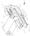
- Figure 1 there is shown a bending machine in a fragmentary perspective view.
- a bend die or matrix 2 On a support bench 1 which is connected to the rest of the bending machine (not shown), a bend die or matrix 2 is mounted around a rotating spindle 3, and a bend arm generally indicated as 4, is mounted around the same rotating spindle 3.
- a vice 5 using a double-acting cylinder 6 to clamp a section of a pipe to be bent (not shown) in its start or initial bending position is situated on the bend arm 4.
- a bending pipe operation on the matrix is performed for a pipe section corresponding to said set angle.
- hoses feeding a pressured fluid for the double-acting cylinder 6 and a hose for wires of an electric circuit are shown in Figure 1 and generally indicated as 7.
- the plurality of hoses can be different from a number of three.
- hoses 7 are shown as cut. However, it should be understood that they extend to the double-acting cylinder 6 and other served parts.
- hoses 7 have a feature that they do not remain hanging from the bend arm 4, as in prior art bending machines. In such a way there are not dangerous hindrances or obstacles to a bending operation, since, as explained below, hoses 7 are kept adjoined to the bend arm 4.
- hoses 7 are arranged in a generally parallel, preferably side by side vertical relationship, i.e. beside the bend arm 4.
- hoses 7 As mounted on the bend arm 4, hoses 7 have a curved section 7a with a concavity facing the rotating spindle 3.
- the curved section 7a is radiused at one end thereof to a section 7b parallel to the bend arm 4, and at the other end to a section 7c respectively, directed to the rest of the bending machine.
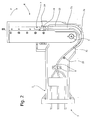
- hoses which are retained at least in a point of the bending device, e.g. by two brackets 8, 8 facing each other ( Figure 2).
- hoses 7 are clamped by a slider 9 slidable in a prismatic guide 10 ( Figure 1) which is provided on the bend arm 4 in an external lateral underside thereof, toward an arrow F indicating a direction in which the bend arm 4 rotates from its start position shown in Figure 1.
- the slider 9 has an U-shaped base plate 11, which is provided in its bottom with engagement projections (not shown) for a slidable joint with the prismatic guide 10, and a closure element 12 adapted to be fixed by screws to sides of the U-shaped base plate 11 to enclose and clamp the hoses 7.
- a protective flexible tape member 13 is provided opposite the bending machine beside the hoses 7.
- the protective flexible tape member 13 is fixed at one end to the slider 9, e.g. by a screw 14 ( Figure 2) and at the other end thereof is constrained to swing around a sliding guide in the form of a pin 15 on which also hoses 7 abut laterally.
- the flexible tape member 13 is made of a spring steel.
- the bend arm 4 In the operation of the bending machine, the bend arm 4 is rotated in the direction of the arrow F to bend a pipe which is clamped by the vice 5.
- hoses 7 being retained by brackets 8, 8 underneath the support bench 1 are caused to extend parallel to a side of the bend arm 4.
- Hoses 7 really extend but without projecting downward from the bend arm 4, since they are clamped by the slider 9 slidable in the prismatic guide 10.
- the protective flexible tape member 13 protects hoses 7 as well as helps the slider 9 slide in the prismatic guide 10.
- hoses 7 continue inside the bending machine through an extension of its support bench 1 to both a source of pressured fluid and a hydraulic unit that are not described in detail.
Landscapes
- Engineering & Computer Science (AREA)
- Mechanical Engineering (AREA)
- Bending Of Plates, Rods, And Pipes (AREA)
Applications Claiming Priority (1)
| Application Number | Priority Date | Filing Date | Title |
|---|---|---|---|
| IT000048A ITRM20050048A1 (it) | 2005-02-04 | 2005-02-04 | Macchina curvatrice con braccio di curvatura a ingombro ridotto. |
Publications (2)
| Publication Number | Publication Date |
|---|---|
| EP1688193A1 true EP1688193A1 (de) | 2006-08-09 |
| EP1688193B1 EP1688193B1 (de) | 2007-11-14 |
Family
ID=36204359
Family Applications (1)
| Application Number | Title | Priority Date | Filing Date |
|---|---|---|---|
| EP06425056A Expired - Lifetime EP1688193B1 (de) | 2005-02-04 | 2006-02-02 | Biegevorrichtung mit kompakter Biegearm |
Country Status (10)
| Country | Link |
|---|---|
| US (1) | US7181947B2 (de) |
| EP (1) | EP1688193B1 (de) |
| KR (1) | KR100686624B1 (de) |
| CN (1) | CN100393440C (de) |
| AT (1) | ATE378123T1 (de) |
| CA (1) | CA2534717C (de) |
| DE (1) | DE602006000217T2 (de) |
| ES (1) | ES2296278T3 (de) |
| IT (1) | ITRM20050048A1 (de) |
| TW (1) | TWI273934B (de) |
Cited By (1)
| Publication number | Priority date | Publication date | Assignee | Title |
|---|---|---|---|---|
| CN102205364A (zh) * | 2011-03-21 | 2011-10-05 | 浙江金马逊机械有限公司 | 一种用于弯管机的避让型连体主夹机构和弯管机 |
Families Citing this family (9)
| Publication number | Priority date | Publication date | Assignee | Title |
|---|---|---|---|---|
| AU2011204164B2 (en) * | 2010-01-06 | 2014-01-30 | Nippon Steel Corporation | Method and apparatus for manufacturing a bent member |
| CN101879540B (zh) * | 2010-06-28 | 2013-01-09 | 吴龙波 | 便携式数控液压弯管弯排机 |
| CN103084447B (zh) * | 2013-01-31 | 2015-03-11 | 中山市奥翔机械有限公司 | 一种弯管机的夹紧机构 |
| IT201800010409A1 (it) * | 2018-11-16 | 2020-05-16 | Cml Int S P A | Macchina per curvare un pezzo allungato senza formazione di grinze |
| CN110666012B (zh) * | 2019-10-11 | 2020-11-10 | 含山县荣源金属制品有限公司 | 铜管弯管机 |
| FR3105034B1 (fr) * | 2019-12-23 | 2021-11-19 | Numalliance | Machine et procédé de cintrage |
| CN116116960B (zh) * | 2023-04-17 | 2023-08-08 | 河北启帆教学设备制造有限公司 | 一种篮球架加工用的弯管机 |
| CN116713354B (zh) * | 2023-04-23 | 2026-01-09 | 江西兴宇汽车零部件有限公司 | 一种汽车门窗框用钣金拉弯机 |
| CN118321407B (zh) * | 2024-06-11 | 2024-10-08 | 常州市盛诺管业有限公司 | 一种用于钢管生产的折弯装置及方法 |
Citations (3)
| Publication number | Priority date | Publication date | Assignee | Title |
|---|---|---|---|---|
| US2777500A (en) * | 1955-03-04 | 1957-01-15 | Flexonics Corp | Tube bending apparatus and method |
| JPH10128631A (ja) * | 1996-10-28 | 1998-05-19 | Amada Eng Center:Kk | 油圧ホース支持装置 |
| JP2004141891A (ja) * | 2002-10-22 | 2004-05-20 | Comco Corp | パイプベンダー、およびパイプ曲げ加工方法 |
Family Cites Families (4)
| Publication number | Priority date | Publication date | Assignee | Title |
|---|---|---|---|---|
| US2306223A (en) * | 1941-03-31 | 1942-12-22 | Parker | Automatic tube bending machine |
| US3156287A (en) * | 1961-12-12 | 1964-11-10 | Pines Engineering Co Inc | Control means for metal forming apparatus |
| US3287952A (en) * | 1963-04-06 | 1966-11-29 | Hilgers Maschinen Und Appbau A | Bending machine |
| CN2180354Y (zh) * | 1993-10-29 | 1994-10-26 | 圣闵机械有限公司 | 管件自动弯弧机 |
-
2005
- 2005-02-04 IT IT000048A patent/ITRM20050048A1/it unknown
-
2006
- 2006-01-26 TW TW095103030A patent/TWI273934B/zh not_active IP Right Cessation
- 2006-01-31 CA CA002534717A patent/CA2534717C/en not_active Expired - Fee Related
- 2006-02-01 US US11/344,120 patent/US7181947B2/en not_active Expired - Lifetime
- 2006-02-02 AT AT06425056T patent/ATE378123T1/de not_active IP Right Cessation
- 2006-02-02 EP EP06425056A patent/EP1688193B1/de not_active Expired - Lifetime
- 2006-02-02 DE DE602006000217T patent/DE602006000217T2/de not_active Expired - Lifetime
- 2006-02-02 ES ES06425056T patent/ES2296278T3/es not_active Expired - Lifetime
- 2006-02-03 KR KR1020060010497A patent/KR100686624B1/ko not_active Expired - Fee Related
- 2006-02-05 CN CNB2006100067774A patent/CN100393440C/zh not_active Expired - Fee Related
Patent Citations (3)
| Publication number | Priority date | Publication date | Assignee | Title |
|---|---|---|---|---|
| US2777500A (en) * | 1955-03-04 | 1957-01-15 | Flexonics Corp | Tube bending apparatus and method |
| JPH10128631A (ja) * | 1996-10-28 | 1998-05-19 | Amada Eng Center:Kk | 油圧ホース支持装置 |
| JP2004141891A (ja) * | 2002-10-22 | 2004-05-20 | Comco Corp | パイプベンダー、およびパイプ曲げ加工方法 |
Non-Patent Citations (2)
| Title |
|---|
| PATENT ABSTRACTS OF JAPAN vol. 1998, no. 10 31 August 1998 (1998-08-31) * |
| PATENT ABSTRACTS OF JAPAN vol. 2003, no. 12 5 December 2003 (2003-12-05) * |
Cited By (1)
| Publication number | Priority date | Publication date | Assignee | Title |
|---|---|---|---|---|
| CN102205364A (zh) * | 2011-03-21 | 2011-10-05 | 浙江金马逊机械有限公司 | 一种用于弯管机的避让型连体主夹机构和弯管机 |
Also Published As
| Publication number | Publication date |
|---|---|
| ATE378123T1 (de) | 2007-11-15 |
| CN100393440C (zh) | 2008-06-11 |
| CA2534717A1 (en) | 2006-08-04 |
| US7181947B2 (en) | 2007-02-27 |
| DE602006000217D1 (de) | 2007-12-27 |
| ES2296278T3 (es) | 2008-04-16 |
| EP1688193B1 (de) | 2007-11-14 |
| TW200628242A (en) | 2006-08-16 |
| KR20060089664A (ko) | 2006-08-09 |
| TWI273934B (en) | 2007-02-21 |
| US20060174673A1 (en) | 2006-08-10 |
| DE602006000217T2 (de) | 2008-09-11 |
| CN1814369A (zh) | 2006-08-09 |
| CA2534717C (en) | 2009-04-14 |
| KR100686624B1 (ko) | 2007-02-26 |
| ITRM20050048A1 (it) | 2006-08-05 |
Similar Documents
| Publication | Publication Date | Title |
|---|---|---|
| EP1688193B1 (de) | Biegevorrichtung mit kompakter Biegearm | |
| US7159430B2 (en) | Bending device with cutting mechanism | |
| CN108943000A (zh) | 工件夹持装置 | |
| CN106660095A (zh) | 具有弯曲单元的压弯机以及用于成形的方法 | |
| EP0407443B1 (de) | Faltvorrichtung | |
| EP1683589A1 (de) | Biegevorrichtung für Biegemaschine | |
| CN207479468U (zh) | 电缆裁切一体机 | |
| US6684731B1 (en) | Holding arm for energy supply | |
| US20060174672A1 (en) | Bending machine with a controlled-return bending die | |
| JP3585345B2 (ja) | 溶接ガン支持装置 | |
| CN113231709B (zh) | 一种焊锡设备、焊锡机构及其整形组件 | |
| CN109604900B (zh) | 一种用于焊接蜗壳支撑块的定位装置 | |
| CN217317054U (zh) | 一种高压钢管定位工装 | |
| CN207205594U (zh) | 一种焊线机 | |
| CN111036734A (zh) | 一种自动弯管机 | |
| KR20140031625A (ko) | 와이퍼 암 제조용 하향 트위스트 밴딩머신 | |
| CN210099646U (zh) | 用于机器人打磨抛光钢丝钳的上料定位装置 | |
| CN209753886U (zh) | 送丝机械手 | |
| JP4698094B2 (ja) | 切断機 | |
| CN220178621U (zh) | 一种手指陀螺安装装置 | |
| CN112518271B (zh) | 机械手自动换轮装置 | |
| CN209936325U (zh) | 一种管类加工生产线 | |
| CN220547705U (zh) | 一种弯管切割夹具 | |
| KR200331984Y1 (ko) | 파이프 밴딩장치 | |
| CN218398904U (zh) | 一种工字轮零点定位装置 |
Legal Events
| Date | Code | Title | Description |
|---|---|---|---|
| PUAI | Public reference made under article 153(3) epc to a published international application that has entered the european phase |
Free format text: ORIGINAL CODE: 0009012 |
|
| AK | Designated contracting states |
Kind code of ref document: A1 Designated state(s): AT BE BG CH CY CZ DE DK EE ES FI FR GB GR HU IE IS IT LI LT LU LV MC NL PL PT RO SE SI SK TR |
|
| AX | Request for extension of the european patent |
Extension state: AL BA HR MK YU |
|
| 17P | Request for examination filed |
Effective date: 20060707 |
|
| AKX | Designation fees paid |
Designated state(s): AT BE BG CH CY CZ DE DK EE ES FI FR GB GR HU IE IS IT LI LT LU LV MC NL PL PT RO SE SI SK TR |
|
| GRAP | Despatch of communication of intention to grant a patent |
Free format text: ORIGINAL CODE: EPIDOSNIGR1 |
|
| GRAS | Grant fee paid |
Free format text: ORIGINAL CODE: EPIDOSNIGR3 |
|
| GRAA | (expected) grant |
Free format text: ORIGINAL CODE: 0009210 |
|
| AK | Designated contracting states |
Kind code of ref document: B1 Designated state(s): AT BE BG CH CY CZ DE DK EE ES FI FR GB GR HU IE IS IT LI LT LU LV MC NL PL PT RO SE SI SK TR |
|
| REG | Reference to a national code |
Ref country code: GB Ref legal event code: FG4D |
|
| REG | Reference to a national code |
Ref country code: CH Ref legal event code: EP |
|
| REG | Reference to a national code |
Ref country code: IE Ref legal event code: FG4D |
|
| REF | Corresponds to: |
Ref document number: 602006000217 Country of ref document: DE Date of ref document: 20071227 Kind code of ref document: P |
|
| REG | Reference to a national code |
Ref country code: ES Ref legal event code: FG2A Ref document number: 2296278 Country of ref document: ES Kind code of ref document: T3 |
|
| PG25 | Lapsed in a contracting state [announced via postgrant information from national office to epo] |
Ref country code: CH Free format text: LAPSE BECAUSE OF FAILURE TO SUBMIT A TRANSLATION OF THE DESCRIPTION OR TO PAY THE FEE WITHIN THE PRESCRIBED TIME-LIMIT Effective date: 20071114 Ref country code: LI Free format text: LAPSE BECAUSE OF FAILURE TO SUBMIT A TRANSLATION OF THE DESCRIPTION OR TO PAY THE FEE WITHIN THE PRESCRIBED TIME-LIMIT Effective date: 20071114 Ref country code: NL Free format text: LAPSE BECAUSE OF FAILURE TO SUBMIT A TRANSLATION OF THE DESCRIPTION OR TO PAY THE FEE WITHIN THE PRESCRIBED TIME-LIMIT Effective date: 20071114 Ref country code: SE Free format text: LAPSE BECAUSE OF FAILURE TO SUBMIT A TRANSLATION OF THE DESCRIPTION OR TO PAY THE FEE WITHIN THE PRESCRIBED TIME-LIMIT Effective date: 20080214 |
|
| NLV1 | Nl: lapsed or annulled due to failure to fulfill the requirements of art. 29p and 29m of the patents act | ||
| PG25 | Lapsed in a contracting state [announced via postgrant information from national office to epo] |
Ref country code: LT Free format text: LAPSE BECAUSE OF FAILURE TO SUBMIT A TRANSLATION OF THE DESCRIPTION OR TO PAY THE FEE WITHIN THE PRESCRIBED TIME-LIMIT Effective date: 20071114 Ref country code: BG Free format text: LAPSE BECAUSE OF FAILURE TO SUBMIT A TRANSLATION OF THE DESCRIPTION OR TO PAY THE FEE WITHIN THE PRESCRIBED TIME-LIMIT Effective date: 20080214 Ref country code: LV Free format text: LAPSE BECAUSE OF FAILURE TO SUBMIT A TRANSLATION OF THE DESCRIPTION OR TO PAY THE FEE WITHIN THE PRESCRIBED TIME-LIMIT Effective date: 20071114 Ref country code: FI Free format text: LAPSE BECAUSE OF FAILURE TO SUBMIT A TRANSLATION OF THE DESCRIPTION OR TO PAY THE FEE WITHIN THE PRESCRIBED TIME-LIMIT Effective date: 20071114 Ref country code: PL Free format text: LAPSE BECAUSE OF FAILURE TO SUBMIT A TRANSLATION OF THE DESCRIPTION OR TO PAY THE FEE WITHIN THE PRESCRIBED TIME-LIMIT Effective date: 20071114 Ref country code: IS Free format text: LAPSE BECAUSE OF FAILURE TO SUBMIT A TRANSLATION OF THE DESCRIPTION OR TO PAY THE FEE WITHIN THE PRESCRIBED TIME-LIMIT Effective date: 20080314 Ref country code: SI Free format text: LAPSE BECAUSE OF FAILURE TO SUBMIT A TRANSLATION OF THE DESCRIPTION OR TO PAY THE FEE WITHIN THE PRESCRIBED TIME-LIMIT Effective date: 20071114 |
|
| REG | Reference to a national code |
Ref country code: CH Ref legal event code: PL |
|
| PG25 | Lapsed in a contracting state [announced via postgrant information from national office to epo] |
Ref country code: AT Free format text: LAPSE BECAUSE OF FAILURE TO SUBMIT A TRANSLATION OF THE DESCRIPTION OR TO PAY THE FEE WITHIN THE PRESCRIBED TIME-LIMIT Effective date: 20071114 |
|
| ET | Fr: translation filed | ||
| PG25 | Lapsed in a contracting state [announced via postgrant information from national office to epo] |
Ref country code: DK Free format text: LAPSE BECAUSE OF FAILURE TO SUBMIT A TRANSLATION OF THE DESCRIPTION OR TO PAY THE FEE WITHIN THE PRESCRIBED TIME-LIMIT Effective date: 20071114 Ref country code: CZ Free format text: LAPSE BECAUSE OF FAILURE TO SUBMIT A TRANSLATION OF THE DESCRIPTION OR TO PAY THE FEE WITHIN THE PRESCRIBED TIME-LIMIT Effective date: 20071114 |
|
| PG25 | Lapsed in a contracting state [announced via postgrant information from national office to epo] |
Ref country code: SK Free format text: LAPSE BECAUSE OF FAILURE TO SUBMIT A TRANSLATION OF THE DESCRIPTION OR TO PAY THE FEE WITHIN THE PRESCRIBED TIME-LIMIT Effective date: 20071114 Ref country code: BE Free format text: LAPSE BECAUSE OF FAILURE TO SUBMIT A TRANSLATION OF THE DESCRIPTION OR TO PAY THE FEE WITHIN THE PRESCRIBED TIME-LIMIT Effective date: 20071114 Ref country code: RO Free format text: LAPSE BECAUSE OF FAILURE TO SUBMIT A TRANSLATION OF THE DESCRIPTION OR TO PAY THE FEE WITHIN THE PRESCRIBED TIME-LIMIT Effective date: 20071114 |
|
| PLBE | No opposition filed within time limit |
Free format text: ORIGINAL CODE: 0009261 |
|
| STAA | Information on the status of an ep patent application or granted ep patent |
Free format text: STATUS: NO OPPOSITION FILED WITHIN TIME LIMIT |
|
| PG25 | Lapsed in a contracting state [announced via postgrant information from national office to epo] |
Ref country code: PT Free format text: LAPSE BECAUSE OF FAILURE TO SUBMIT A TRANSLATION OF THE DESCRIPTION OR TO PAY THE FEE WITHIN THE PRESCRIBED TIME-LIMIT Effective date: 20080414 |
|
| 26N | No opposition filed |
Effective date: 20080815 |
|
| PG25 | Lapsed in a contracting state [announced via postgrant information from national office to epo] |
Ref country code: MC Free format text: LAPSE BECAUSE OF NON-PAYMENT OF DUE FEES Effective date: 20080228 |
|
| PG25 | Lapsed in a contracting state [announced via postgrant information from national office to epo] |
Ref country code: GR Free format text: LAPSE BECAUSE OF FAILURE TO SUBMIT A TRANSLATION OF THE DESCRIPTION OR TO PAY THE FEE WITHIN THE PRESCRIBED TIME-LIMIT Effective date: 20080215 Ref country code: IE Free format text: LAPSE BECAUSE OF NON-PAYMENT OF DUE FEES Effective date: 20080204 Ref country code: EE Free format text: LAPSE BECAUSE OF FAILURE TO SUBMIT A TRANSLATION OF THE DESCRIPTION OR TO PAY THE FEE WITHIN THE PRESCRIBED TIME-LIMIT Effective date: 20071114 |
|
| PG25 | Lapsed in a contracting state [announced via postgrant information from national office to epo] |
Ref country code: CY Free format text: LAPSE BECAUSE OF FAILURE TO SUBMIT A TRANSLATION OF THE DESCRIPTION OR TO PAY THE FEE WITHIN THE PRESCRIBED TIME-LIMIT Effective date: 20071114 |
|
| PG25 | Lapsed in a contracting state [announced via postgrant information from national office to epo] |
Ref country code: LU Free format text: LAPSE BECAUSE OF NON-PAYMENT OF DUE FEES Effective date: 20080202 Ref country code: HU Free format text: LAPSE BECAUSE OF FAILURE TO SUBMIT A TRANSLATION OF THE DESCRIPTION OR TO PAY THE FEE WITHIN THE PRESCRIBED TIME-LIMIT Effective date: 20080515 |
|
| GBPC | Gb: european patent ceased through non-payment of renewal fee |
Effective date: 20100202 |
|
| PG25 | Lapsed in a contracting state [announced via postgrant information from national office to epo] |
Ref country code: IT Free format text: LAPSE BECAUSE OF NON-PAYMENT OF DUE FEES Effective date: 20080229 |
|
| PG25 | Lapsed in a contracting state [announced via postgrant information from national office to epo] |
Ref country code: GB Free format text: LAPSE BECAUSE OF NON-PAYMENT OF DUE FEES Effective date: 20100202 |
|
| PGFP | Annual fee paid to national office [announced via postgrant information from national office to epo] |
Ref country code: TR Payment date: 20120202 Year of fee payment: 7 Ref country code: DE Payment date: 20120228 Year of fee payment: 7 |
|
| PGFP | Annual fee paid to national office [announced via postgrant information from national office to epo] |
Ref country code: FR Payment date: 20130301 Year of fee payment: 8 |
|
| REG | Reference to a national code |
Ref country code: DE Ref legal event code: R119 Ref document number: 602006000217 Country of ref document: DE Effective date: 20130903 |
|
| PG25 | Lapsed in a contracting state [announced via postgrant information from national office to epo] |
Ref country code: DE Free format text: LAPSE BECAUSE OF NON-PAYMENT OF DUE FEES Effective date: 20130903 |
|
| REG | Reference to a national code |
Ref country code: FR Ref legal event code: ST Effective date: 20141031 |
|
| PG25 | Lapsed in a contracting state [announced via postgrant information from national office to epo] |
Ref country code: FR Free format text: LAPSE BECAUSE OF NON-PAYMENT OF DUE FEES Effective date: 20140228 |
|
| PG25 | Lapsed in a contracting state [announced via postgrant information from national office to epo] |
Ref country code: TR Free format text: LAPSE BECAUSE OF NON-PAYMENT OF DUE FEES Effective date: 20130202 |
|
| PGFP | Annual fee paid to national office [announced via postgrant information from national office to epo] |
Ref country code: ES Payment date: 20180720 Year of fee payment: 13 |
|
| REG | Reference to a national code |
Ref country code: ES Ref legal event code: FD2A Effective date: 20200327 |
|
| PG25 | Lapsed in a contracting state [announced via postgrant information from national office to epo] |
Ref country code: ES Free format text: LAPSE BECAUSE OF NON-PAYMENT OF DUE FEES Effective date: 20190203 |