EP1688342A2 - Fahrzeug - Google Patents
Fahrzeug Download PDFInfo
- Publication number
- EP1688342A2 EP1688342A2 EP06002380A EP06002380A EP1688342A2 EP 1688342 A2 EP1688342 A2 EP 1688342A2 EP 06002380 A EP06002380 A EP 06002380A EP 06002380 A EP06002380 A EP 06002380A EP 1688342 A2 EP1688342 A2 EP 1688342A2
- Authority
- EP
- European Patent Office
- Prior art keywords
- cowl
- wind
- radiator
- discharge ports
- travel
- Prior art date
- Legal status (The legal status is an assumption and is not a legal conclusion. Google has not performed a legal analysis and makes no representation as to the accuracy of the status listed.)
- Granted
Links
- 230000006698 induction Effects 0.000 claims description 16
- 238000007599 discharging Methods 0.000 claims description 9
- 230000001939 inductive effect Effects 0.000 claims description 7
- 238000010276 construction Methods 0.000 description 4
- 239000002828 fuel tank Substances 0.000 description 4
- 239000000725 suspension Substances 0.000 description 3
- 230000005540 biological transmission Effects 0.000 description 2
- 238000001816 cooling Methods 0.000 description 2
- 239000000446 fuel Substances 0.000 description 2
- 238000002347 injection Methods 0.000 description 2
- 239000007924 injection Substances 0.000 description 2
- 238000007664 blowing Methods 0.000 description 1
- 230000000694 effects Effects 0.000 description 1
- 239000000463 material Substances 0.000 description 1
- 239000002990 reinforced plastic Substances 0.000 description 1
- 239000011347 resin Substances 0.000 description 1
- 229920005989 resin Polymers 0.000 description 1
Images


Classifications
-
- B—PERFORMING OPERATIONS; TRANSPORTING
- B62—LAND VEHICLES FOR TRAVELLING OTHERWISE THAN ON RAILS
- B62J—CYCLE SADDLES OR SEATS; AUXILIARY DEVICES OR ACCESSORIES SPECIALLY ADAPTED TO CYCLES AND NOT OTHERWISE PROVIDED FOR, e.g. ARTICLE CARRIERS OR CYCLE PROTECTORS
- B62J17/00—Weather guards for riders; Fairings or stream-lining parts not otherwise provided for
- B62J17/02—Weather guards for riders; Fairings or stream-lining parts not otherwise provided for shielding only the rider's front
-
- B—PERFORMING OPERATIONS; TRANSPORTING
- B62—LAND VEHICLES FOR TRAVELLING OTHERWISE THAN ON RAILS
- B62J—CYCLE SADDLES OR SEATS; AUXILIARY DEVICES OR ACCESSORIES SPECIALLY ADAPTED TO CYCLES AND NOT OTHERWISE PROVIDED FOR, e.g. ARTICLE CARRIERS OR CYCLE PROTECTORS
- B62J17/00—Weather guards for riders; Fairings or stream-lining parts not otherwise provided for
- B62J17/10—Ventilation or air guiding devices forming part of fairings
Definitions
- the present invention relates to a vehicle, in particular a motorcycle, according to the preamble portion of claim 1, provided with a radiator ahead of an engine, and adapted to discharge the wind passed through the radiator from wind discharge ports provided in side walls of a front cowl to the outside of a vehicle.
- an engine is disposed in a longitudinally central portion of a vehicle body, a radiator ahead of the engine, a front cowl on a front portion of the vehicle body so as to cover a front surface of the vehicle body to side surfaces thereof, and a wind discharge ports, which are adapted to discharge the wind passed through the radiator, in side walls of the front cowl (refer to JP-UM-B-5-9995, JP-UM-B-4-50228, and JP-A-62-283082).
- the travel wind passing through a radiator while a motorcycle travels enters an opening in the center of a front wall of a front cowl and passes through the radiator, and a part of the wind flows out from wind discharge ports in side walls of the front cowl to the outside of the vehicle, the wind flowing rearward as the wind is carried on the travel wind flowing along side surfaces of the front cowl.
- the wind coming out from the wind discharge ports is only carried on the wind flowing along the surface of the front cowl, so that a great discharge effect could not be expected.
- the present invention aims at providing a vehicle, in particular a motorcycle, capable of positively improving the discharge efficiency of the wind passed through a radiator to the outside of a vehicle body.
- a vehicle in particular motorcycle comprising an engine and a radiator arranged ahead of the engine, wherein radiator-passed air is discharged from wind discharge ports provided in side walls of a front cowl covering a front of the motorcycle, and further comprising vent passages formed in the front cowl and being arranged above the wind discharge ports, said vent passages being adapted to introduce travel air and to make the travel wind flow rearward.
- the vehicle further comprises a body frame, wherein the engine is supported on the body frame, the radiator is provided ahead of the engine, the front cowl is provided so as to cover a front surface of the body frame and side regions of a front portion of the body frame including the radiator and the discharge ports being formed in the side walls of the front cowl, are opened in the portion of side walls of the front cowl, which are behind the radiator and adapted to discharge travel wind passed through the radiator, wherein side walls of a front end of the portions of the front cowl, which are arranged above the discharge ports for the travel wind passed through the radiator are provided with the vent passages for introducing the travel wind from the front end and for making the travel wind flow rearward.
- vent passages are provided with extensions made longer longitudinally up to positions immediately above the discharge ports for discharging the travel wind passed through the radiator.
- an upper-cowl is fixed to the body frame, the extensions of the vent passages being formed on the upper-cowl.
- induction passages for inducing the travel wind, which rearwardly flows from the vent passages, in the outward direction are provided in rear end regions of the extensions of the vent passages.
- the induction passages are inclined in the rearward downward direction.
- the upper-cowl is provided with recesses extending inward in the direction of the width of the body frame, the vent passages being formed between the recesses and a panel-type middle-cowl fixed to the upper-cowl so that the middle-cowl covers the outer side of the upper cowl.
- the middle-cowl extends in the longitudinal direction so as to vertically divide the discharge ports for the travel wind passed through the radiator, the discharge ports being formed above the middle-cowl and including lower wind discharge ports formed above the middle-cowls and adapted to discharge the travel wind passed through an upper portion of the radiator, and lower wind discharge ports formed below the middle-cowl and adapted to discharge the travel wind passed through a lower portion of the radiator.
- an under-cowl which is fixed to the body frame and is adapted to cover the engine from a lower portion thereof to side portions thereof, the middle-cowl being fixed between the upper-cowl and under-cowl, the wind discharge ports at the upper side of the middle-cowl being used as upper air discharge ports, and the wind discharge ports at the lower side of the middle-cowl being used as lower air discharge ports.
- a headlamp on a front portion of the front cowl, the travel wind passages being provided between the headlamp and the radiator.
- Fig. 1 is a left side view showing the construction of the motorcycle as a whole in an embodiment
- Fig. 2 a right side view showing the construction of the same
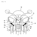
- Fig. 3 a front view of an upper portion of the same motorcycle
- Fig. 4 a drawing showing the same motorcycle viewed from a diagonally front side thereof
- Fig. 5 a drawing showing an important portion of the same motorcycle viewed from a diagonally rear side thereof
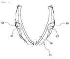
- Fig. 6 a front view of a front cowl
- Fig. 7 a side view of the same front cowl
- Fig. 8 an enlarged side view showing an upper portion of the same front cowl
- Fig. 9 a half sectional view taken along the arrow-carrying line IX-IX in Fig. 8, Fig.
- Fig. 10 a front view of an under-cowl alone constituting a front cowl lower
- Fig. 11 a side view of the same
- Fig. 12 a side view of an upper-cowl constituting the front cowl lower
- Fig. 13 a side view of a middle cowl constituting the front cowl lower.
- this motorcycle is formed by being provided with a body frame 20, a front wheel 2, a rear wheel 2, an engine 3, a radiator 4, a front fork 5, a handlebar 6, a fuel tank 7, an air cleaner 8, a fuel injection system 9, a pivot 10, a rear frame 11, a swing arm 12, a power transmission 13, a seat 14, a rear suspension 15, an exhaust pipe 16, a muffler 17, a front cowl 50 and the like.
- the body frame 20 has left and right main frames extending from a head pipe 21 at a front end in the diagonally downward and rearward direction.
- rear frames 11 are connected, and, to the lower side of the rear portions of the main frames, swing arms 12 are connected so that the swing arms can be turned vertically via a pivot 10.
- a rear wheel 2 is supported, and, between the swing arms 12 and rear frames 11, rear suspensions 15 are provided.
- a handlebar 6 On the head pipe 21 at a front end of the body frame 20, a handlebar 6 is pivotably supported, and, to the lower side of the handlebar 6, the front forks 5 maneuvered by the handlebar 6 are connected, the front wheel 1 being suspended from lower ends of the front forks 5.
- the engine 3 is provided in a longitudinally central portion, and suspended from an engine suspension frame 23 provided on the lower side of and made integral with the main frame 22 of the body frame 20.
- This engine is a parallel 4-cylinder engine, and mounted in a transversely laid state, a cylinder 3A above a crank case being slightly inclined. Since the engine 3 is thus mounted, the engine 3 takes a position below the position between the left and right main frames.
- the four exhaust pipes 16 are joined to exhaust port on the front side of the vehicle body of the cylinder 3A, and thereafter the exhaust pipes pass the underside of the engine 3 while the meeting of the same pipes is done repeatedly midway through the extension of the same pipes, the exhaust pipes being finally connected to the muffler 17.
- the radiator 4 is disposed in a position of the height substantially equal to that of the cylinder 3A provided ahead of the engine 3 with a wind passing surface facing in the forward direction.
- a fan 4A is provided on the rear side of the radiator 4.
- the air cleaner 8 and fuel injection system 9 are provided above the engine 3, and, on the rear side thereof, the fuel tank 7 is provided above the main frame 22.
- the seat 14 on which a rider is to sit is placed on the rear frame 11.
- electrical equipment, such as a battery 18A, a relay 18B, and ECU (engine control unit) 18C is arranged on the rear frame 11.
- the power transmission system 13 is provided at the left side of the rear portion of the vehicle body, and the muffler 17 at the right side of the rear portion of the vehicle body.
- the front cowl 50 will now be described in detail with reference to mainly Fig. 6 to Fig. 13.
- the front cowl 50 is provided in the range from an instrument panel provided ahead of the handlebar 6 to a position in which both the left and right sides of the engine 3 and exhaust pipe 16 are covered thereby.
- the front cowl 50 is formed by a combination of a front cowl upper 51 and a front cowl lower 52 both of which are made of a reinforced plastic material.
- the front cowl upper 51 is so large as to cover the parts in the vicinity of the portion of the vehicle which is ahead of the handlebar 6, and the front cowl lower 52 is so large as to cover the range from a lower edge portion of the front cowl upper 51 to the side portions of the engine 3.
- the front cowl 50 is provided at a central portion of a front wall thereof with a central port 66 from which the travel wind toward the radiator 4 is taken in, and the radiator 4 is positioned at the rear side of this central port 66.
- Left and right headlamps 54 are fitted in the front cowl upper 51 which is streamlined as a whole, and an air suction port 55 for sucking the air into the air cleaner 8 is provided between the left and right headlamps 54.
- a windscreen 56 of a transparent resin extending in the diagonally upward rearward direction so as to cover the instrument panel from the front side thereof is fitted in a central upper portion of the front cowl upper.
- recesses 57 extending from the front side to the rear side are provided along the longitudinal curves of the two side surfaces.
- the front cowl lower 52 in front elevation has the central port 66, and includes an under-cowl 61 (refer to Fig. 10 and Fig. 11) so large as to cover both sides of the radiator 4 and exhaust pipe 16, a hooked upper-cowl 62 (refer to Fig. 12) provided in a spaced manner with respect to the under-cowl 61, extending along the main frame 22, and connected at a front end to the front cowl upper 51 in one body, and knife-shaped panel type middle cowls 63 (refer to Fig. 13) provided between the under-cowl 61 and upper-cowl 62.
- a space between the under-cowl 61 and upper-cowl 62 with the middle-cowls 63 removed is set so large as to open the greater parts of the side surfaces of the engine 3 and a part of each of the side surfaces of the radiator 4.
- the middle-cowls 63 have sizes not so large as to cover the opened portion as a whole opened between the under-cowl 61 and upper-cowl 62.
- the middle-cowls 63 extend longitudinally so as to vertically divide the wind discharge port for the wind passed through the radiator.
- a lower wind discharge port 71 for discharging the wind passed through the radiator 4 is formed, and, between the middle-cowls 63 and upper-cowl 62, an upper wind discharge port 72 for discharging the wind passed through the radiator 4 is formed.
- the upper wind discharge port 72 is a discharge port mainly for the wind passed through an upper portion 4U of the radiator 4
- the lower wind discharge port 71 is a discharge port mainly for the wind passed through a lower portion 4D of the radiator 4.
- the upper-cowl 62 bent in the shape of a hook in side elevation is cross-sectionally mountain-shaped, and a highest ridge portion 62a and an inner inclined surface 62b is made of a path bent in the shape of a hook in side elevation. Therefore, the bent portion of the inclined surface 62b having an apex of the ridge portion 62a constitutes a valley-shaped terminal wall 62c.
- This terminal wall 62c is a part positioned on the side of the rear end when the terminal wall 62c is fixed to the vehicle body, and this position is ahead of a position below which the foot of a driver sitting on the seat is placed (refer to Fig. 5). Since the inner inclined surface 62b is made of a hooked path, the inner portion of the upper-cowl 62 forms a recess 62d set back inward in the widthwise direction of the vehicle boy.
- the upper-cowl 62 is sectionally mountain-shaped with the inner inclined surface 62b opposed to the middle-cowls 63 in parallel with an upper edge thereof, so that the upper wind discharge port 72 is seen opened even in side elevation more greatly than the same port seen from a diagonally upper position. Therefore, a radiation-passed wind diagonally upward passes through the upper wind discharged port 72.
- a vent passage 73 positioned above the upper wind discharge port 72 and adapted to pass the travel wind therethrough from the front side to the rear side is formed.
- This vent passage 73 is formed at a front end side portion by the recess 57, and at a rear end side portion by the extension 73E made longer in the longitudinal direction of the vehicle to a position just above the upper wind discharge port 72.
- This extension 73E is formed by combining panel type middle-cowls 63 with the outer portions of the inclined surface 62b and recess 62d of the upper-cowl 62 with a space kept between the two cowls.
- induction passages 73F for inducing the wind, which flows from the vent passages 73 backward, in the outward direction is provided.
- This induction passage 73F is formed by the downwardly sloping inclined surface 62b and ridge portion 62a of each sub-cowl (upper-cowl) 62, and extends in a horizontal section divergently in the rearward direction with the width of the induction passages increasing in the lateral direction of the vehicle. Since the travel wind enters the recesses 57 forcibly, the travel wind flows along the vent passage 73 linearly from the front side to the rear side. Therefore, the travel wind necessarily spreads outward in the widthwise direction of the vehicle and flows rearward as the travel wind is induced by the induction passage 73F formed by the inclined surfaces 62b of the sub-cowl (upper cowl) 62.
- the cross section of the corresponding portions of the vent passage 73 has a shape close to a substantially C-shape. Therefore, the travel wind is taken in easily, and the travel wind taken in is easily led to the rear side without making the same wind escape outside.
- the middle-cowls 63 are fixed to the under-cowl 61 by screws. Since the vent passages 73 can be formed by only combining the middle-cowls 63 in this manner with the upper-cowl 62 from the outer side so as to cover the lower portion of the upper-cowl 62, the forming of the vent passage 73 can be done with ease.
- the outside air induction ducts 80 are provided on the inner side of the under-cowl 61 and middle-cowls 63 so that the front end port is opened the positions in which the travel wind is introduced with the rear port opened toward a space surrounded by the main frame 22, the engine 3 and the fuel tank 7.
- wind discharge passages (drawing is omitted) for further blowing the wind, which is introduced thereinto, toward the rear side is secured.
- the under-cowl 61 of the front cowl lower 52 is provided in the side walls thereof with travel wind intake ports 67 communicating with the front end of the outside air induction duct 80.
- the travel wind intake ports 67 are provided in positions lower than the lower end of the radiator 4, and, in the side walls of the front cowl lower 52 on the upper side of the travel wind intake ports 67, lower side wind discharge ports 71 for the radiator-passed wind are secured.
- a part of the wind passed through the radiator 4 during the traveling of the vehicle flows out upward or rearward from the upper wind discharge ports 72 provided in side walls of the front cowl 50.
- the travel wind F flows straight at a high speed in the vent passage 73, which is positioned above the wind discharge port 72, from the front end thereof in the rearward direction.
- the radiator-passed hot air-containing wind is positively discharged from the upper wind discharge port 72 to the outside. Therefore, the heat in the front cowl 50 can be discharged efficiently to the outside.
- the vent passage 73 extends in the longitudinal direction of the vehicle up to a position just above the upper wind discharge port 72, the hot air passed through the radiator 4 can be made to flow smoothly in the rearward direction. Since the induction passages 73F for inducing the wind flowing rearward in the vent passages 73 outward is provided on the rear ends of the extensions 73E of the vent passages 73, the hot wind from the radiator 4 can be induced outward in positions in front of the legs of the driver, and thus, the hot wind can be prevented from hitting on the legs of the driver. Accordingly, the unpleasant feeling occurring due to the hot air hitting on the driver's legs, especially, in summer is eliminated.
- vent passages 73 mentioned above are formed with the positions shunning the headlamp 54 and radiator 4, a vacant space can be effectively utilized.
- a motorcycle provided with a body frame, an engine supported on the body frame, a radiator provided ahead of the engine, a front cowl provided so as to cover a front surface of the body and side regions of a front portion thereof including the radiator, and discharge ports opened in the portions of side walls of the front cowl which are behind the radiator, and adapted to discharge the wind passed through the radiator, wherein side walls of a front end of the portions of the front cowl which are above the discharge ports, which are formed in the side walls of the front cowl, for the wind passed through the radiator are provided with vent passages for introducing travel wind from the front end and making the travel wind flow rearward.
- the hot wind passed through the radiator is discharged from the discharge ports provided in the side walls of the front cowl to the outside. While the vehicle travels, the travel wind flows through the vent passages, which are positioned above the wind discharge ports, from the front side to the rear side. Owing to the difference in pressure occurring due to the air flow, the radiator-passed wind including hot air is positively discharged from the wind discharge port to the outside. Therefore, the heat in the front cowl can be discharged efficiently to the outside.
- vent passages are provided with extension portions extended longitudinally up to positions immediately above the ports for discharging the wind passed through the radiator.
- vent passages are extended up to positions immediately above the port for discharging the wind passed through the radiator, so that the radiator-passed wind can be made to flow rearward. This enables the heat in the front cowl to be discharged to the outside more efficiently.
- an upper-cowl is fixed to the body frame, the extension portions of the vent passages being formed on the upper-cowl.
- an upper-cowl is fixed to the body frame, and the extension portions of the vent passages are formed on the upper-cowl, so that the forming of the vent passages becomes easier.
- induction passages for inducing the wind, which flows from the vent passages, in the outward direction is provided in a rear end region of the extension portions of the vent passages.
- vent passages are provided at rear ends of the extensions with induction passages for inducing the wind flowing rearward in the vent passages, so that the hot air from the radiator does not hit on the driver's legs.
- the induction passages are inclined in the rearward downward direction.
- the wind flowing in the vent passages can be made to flow rearward and downward, so that the hot wind from the radiator does not hit on the driver's legs.
- the upper-cowl is provided with recesses extending inward in the direction of the width of the body, the vent passages being formed between the recesses and panel type middle-cowl fixed to the upper-cowl so that the middle-cowl covers the outer side of the upper-cowl.
- the panel type middle-cowl is combined from the outside with the upper-cowl so that the recesses formed in the upper-cowl are covered with the middle-cowl, and the vent passages are formed between these cowls. This enables the vent passages to be formed easily.
- the middle-cowl extends in the longitudinal direction so as to vertically divide the discharge ports for the wind passed through the radiator, the discharge ports being formed above the middle-cowl and including upper wind discharge ports formed above the middle-cowl and adapted to discharge the wind passed through an upper portion of the radiator, and lower wind discharge ports formed below the middle-cowl and adapted to discharge the wind passed through a lower portion of the radiator.
- two wind discharge ports i.e. upper and lower wind discharge ports for discharging the wind passing through the radiator are provided. Therefore, even in a case where a cooling operation is carried out only by a radiator fan when the vehicle is stopped, the hot air can be discharged to the outside smoothly.
- an under-cowl which is fixed to the body frame and adapted to cover the engine from a lower portion thereof to side portions thereof, the middle-cowl being fixed between the upper-cowl and under-cowl, the wind discharge ports at the upper side of the middle-cowl being used as upper air discharge ports, the wind discharge ports at the lower side of the middle-cowl being used as lower air discharge ports.
- the upper-cowl can be used both as vent passages and as the upper edges of the upper wind discharge ports.
- headlamps are provided on a front portion of the front cowl, the wind passages being provided between the headlamp and radiator.
- vent passages can be formed with the positions shunning the headlamps and radiator. This enables a vacant space to be effectively utilized.
- vent passages 73 are provided in the portions of the side walls of the front end of the front cowl which are above the wind discharge ports, the vent passages 73 being adapted to introduce the travel wind from the front end make the travel wind flow rearward, the vent passages 73 being provided at rear portions thereof with the extensions 73E made longer up to positions just above the wind discharge ports, and at rear ends of the extensions with the induction passages 73F for inducing the wind, which flows from the vent passages
Landscapes
- Engineering & Computer Science (AREA)
- Mechanical Engineering (AREA)
- Automatic Cycles, And Cycles In General (AREA)
- Cooling, Air Intake And Gas Exhaust, And Fuel Tank Arrangements In Propulsion Units (AREA)
Applications Claiming Priority (1)
| Application Number | Priority Date | Filing Date | Title |
|---|---|---|---|
| JP2005029816A JP2006213249A (ja) | 2005-02-04 | 2005-02-04 | 自動二輪車 |
Publications (3)
| Publication Number | Publication Date |
|---|---|
| EP1688342A2 true EP1688342A2 (de) | 2006-08-09 |
| EP1688342A3 EP1688342A3 (de) | 2009-11-25 |
| EP1688342B1 EP1688342B1 (de) | 2013-04-10 |
Family
ID=36384472
Family Applications (1)
| Application Number | Title | Priority Date | Filing Date |
|---|---|---|---|
| EP06002380.1A Expired - Lifetime EP1688342B1 (de) | 2005-02-04 | 2006-02-06 | Fahrzeug |
Country Status (4)
| Country | Link |
|---|---|
| US (1) | US7399029B2 (de) |
| EP (1) | EP1688342B1 (de) |
| JP (1) | JP2006213249A (de) |
| CN (1) | CN100509534C (de) |
Cited By (4)
| Publication number | Priority date | Publication date | Assignee | Title |
|---|---|---|---|---|
| US7510229B2 (en) * | 2005-09-26 | 2009-03-31 | Honda Motor Co., Ltd. | Vehicle body front structure of saddle-ride type vehicle |
| EP2399809A1 (de) * | 2010-06-28 | 2011-12-28 | Kawasaki Jukogyo Kabushiki Kaisha | Fahrzeuglampenanordnung |
| EP2949555A1 (de) * | 2014-05-30 | 2015-12-02 | Yamaha Hatsudoki Kabushiki Kaisha | Motorrad |
| EP4410648A1 (de) * | 2023-02-02 | 2024-08-07 | Suzuki Motor Corporation | Verkleidungsstruktur |
Families Citing this family (31)
| Publication number | Priority date | Publication date | Assignee | Title |
|---|---|---|---|---|
| JP2006143176A (ja) * | 2004-10-20 | 2006-06-08 | Yamaha Motor Co Ltd | フロントカウル及びそれを備えた車両 |
| JP4584781B2 (ja) * | 2005-06-15 | 2010-11-24 | 本田技研工業株式会社 | 自動二輪車用カウリング構造 |
| JP2007308131A (ja) * | 2006-04-20 | 2007-11-29 | Denso Corp | 自動二輪車用熱交換器 |
| JP2009046018A (ja) * | 2007-08-20 | 2009-03-05 | Yamaha Motor Co Ltd | 鞍乗型車両 |
| JP2009107569A (ja) * | 2007-10-31 | 2009-05-21 | Yamaha Motor Co Ltd | 自動二輪車用カウル及び自動二輪車 |
| JP2009107568A (ja) * | 2007-10-31 | 2009-05-21 | Yamaha Motor Co Ltd | 自動二輪車用カウル及び自動二輪車 |
| JP5142695B2 (ja) * | 2007-12-19 | 2013-02-13 | 本田技研工業株式会社 | 自動2輪車のフロントカウル構造 |
| JP5129672B2 (ja) * | 2008-07-07 | 2013-01-30 | 本田技研工業株式会社 | 自動二輪車の車体カバー構造 |
| EP2311717B1 (de) * | 2008-08-08 | 2014-02-12 | Honda Motor Co., Ltd. | Fahrzeug |
| JP5337540B2 (ja) * | 2009-03-10 | 2013-11-06 | 本田技研工業株式会社 | 鞍乗り型車両のカウリング構造 |
| US8539929B2 (en) * | 2009-11-18 | 2013-09-24 | Harley-Davidson Motor Company | Cylinder head cooling system |
| JP5566708B2 (ja) * | 2010-01-27 | 2014-08-06 | 本田技研工業株式会社 | 鞍乗型車両のカウリング構造 |
| JP5378250B2 (ja) * | 2010-01-27 | 2013-12-25 | 本田技研工業株式会社 | 鞍乗型車両の力ウリング構造 |
| JP5555586B2 (ja) * | 2010-09-29 | 2014-07-23 | 本田技研工業株式会社 | 鞍乗り型車両のフェアリング構造 |
| JP5597147B2 (ja) * | 2011-03-07 | 2014-10-01 | 本田技研工業株式会社 | 鞍乗型車両 |
| JP5771100B2 (ja) | 2011-09-06 | 2015-08-26 | 川崎重工業株式会社 | 鞍乗型車両 |
| JP5921125B2 (ja) * | 2011-10-04 | 2016-05-24 | 川崎重工業株式会社 | 自動二輪車の導風構造 |
| JP5894898B2 (ja) * | 2012-09-28 | 2016-03-30 | 本田技研工業株式会社 | 鞍乗型車両のフロントカウル構造 |
| WO2015071935A1 (ja) * | 2013-11-15 | 2015-05-21 | 川崎重工業株式会社 | 鞍乗型車両 |
| CN105291819B (zh) * | 2014-06-10 | 2018-01-16 | 光阳工业股份有限公司 | 摩托车引擎的散热结构 |
| JP6050296B2 (ja) * | 2014-09-30 | 2016-12-21 | 本田技研工業株式会社 | 鞍乗り型車両のフロントカバー構造 |
| JP6129884B2 (ja) * | 2015-01-23 | 2017-05-17 | 本田技研工業株式会社 | 鞍乗り型車両のサイドカバー構造 |
| JP6225401B2 (ja) * | 2015-08-31 | 2017-11-08 | 本田技研工業株式会社 | 鞍乗り型車両 |
| JP6346631B2 (ja) * | 2016-03-24 | 2018-06-20 | 本田技研工業株式会社 | 鞍乗型車両の前部構造 |
| JP6270895B2 (ja) * | 2016-03-24 | 2018-01-31 | 本田技研工業株式会社 | 鞍乗型車両の前部構造 |
| JP6828158B2 (ja) * | 2017-06-29 | 2021-02-10 | 本田技研工業株式会社 | 自動二輪車 |
| JP6663451B2 (ja) * | 2018-04-26 | 2020-03-11 | 本田技研工業株式会社 | 鞍乗型車両 |
| JP6806747B2 (ja) * | 2018-09-28 | 2021-01-06 | 本田技研工業株式会社 | 鞍乗り型車両のカウル構造 |
| JP7122227B2 (ja) | 2018-11-02 | 2022-08-19 | カワサキモータース株式会社 | 鞍乗型車両 |
| CN113184090B (zh) * | 2021-06-08 | 2024-11-08 | 浙江钱江摩托股份有限公司 | 一种水冷摩托车暖风装置 |
| JP7496385B2 (ja) * | 2022-06-15 | 2024-06-06 | 本田技研工業株式会社 | 鞍乗型車両のフロントカウル構造 |
Citations (3)
| Publication number | Priority date | Publication date | Assignee | Title |
|---|---|---|---|---|
| JPS62283082A (ja) | 1986-05-30 | 1987-12-08 | 本田技研工業株式会社 | 自動二輪車 |
| JPH0450228B2 (de) | 1985-06-28 | 1992-08-13 | Honda Motor Co Ltd | |
| JPH059995B2 (de) | 1983-07-06 | 1993-02-08 | Fujitsu Ltd |
Family Cites Families (5)
| Publication number | Priority date | Publication date | Assignee | Title |
|---|---|---|---|---|
| JPS6055526U (ja) * | 1983-09-26 | 1985-04-18 | 本田技研工業株式会社 | 自動二輪車 |
| JPS63101185A (ja) * | 1986-10-17 | 1988-05-06 | 本田技研工業株式会社 | 自動二輪車 |
| JP2527188B2 (ja) * | 1987-06-19 | 1996-08-21 | 本田技研工業株式会社 | 自動二輪車の風防装置 |
| JP3549162B2 (ja) * | 1990-06-18 | 2004-08-04 | 本田技研工業株式会社 | 自動2輪車用フェアリング |
| JP2006240315A (ja) * | 2003-05-20 | 2006-09-14 | Yamaha Motor Co Ltd | 鞍乗型車両 |
-
2005
- 2005-02-04 JP JP2005029816A patent/JP2006213249A/ja not_active Withdrawn
-
2006
- 2006-01-25 CN CNB2006100062605A patent/CN100509534C/zh not_active Expired - Fee Related
- 2006-02-03 US US11/346,996 patent/US7399029B2/en active Active
- 2006-02-06 EP EP06002380.1A patent/EP1688342B1/de not_active Expired - Lifetime
Patent Citations (3)
| Publication number | Priority date | Publication date | Assignee | Title |
|---|---|---|---|---|
| JPH059995B2 (de) | 1983-07-06 | 1993-02-08 | Fujitsu Ltd | |
| JPH0450228B2 (de) | 1985-06-28 | 1992-08-13 | Honda Motor Co Ltd | |
| JPS62283082A (ja) | 1986-05-30 | 1987-12-08 | 本田技研工業株式会社 | 自動二輪車 |
Cited By (6)
| Publication number | Priority date | Publication date | Assignee | Title |
|---|---|---|---|---|
| US7510229B2 (en) * | 2005-09-26 | 2009-03-31 | Honda Motor Co., Ltd. | Vehicle body front structure of saddle-ride type vehicle |
| DE102006042035B4 (de) * | 2005-09-26 | 2019-10-31 | Honda Motor Co., Ltd. | Fahrzeugkörperfrontstruktur eines Fahrzeugs vom Sattelfahrtyp |
| EP2399809A1 (de) * | 2010-06-28 | 2011-12-28 | Kawasaki Jukogyo Kabushiki Kaisha | Fahrzeuglampenanordnung |
| US8746774B2 (en) | 2010-06-28 | 2014-06-10 | Kawasaki Jukogyo Kabushiki Kaisha | Motorcycle position lamp arrangement |
| EP2949555A1 (de) * | 2014-05-30 | 2015-12-02 | Yamaha Hatsudoki Kabushiki Kaisha | Motorrad |
| EP4410648A1 (de) * | 2023-02-02 | 2024-08-07 | Suzuki Motor Corporation | Verkleidungsstruktur |
Also Published As
| Publication number | Publication date |
|---|---|
| CN100509534C (zh) | 2009-07-08 |
| EP1688342B1 (de) | 2013-04-10 |
| US7399029B2 (en) | 2008-07-15 |
| EP1688342A3 (de) | 2009-11-25 |
| CN1814496A (zh) | 2006-08-09 |
| US20070024089A1 (en) | 2007-02-01 |
| JP2006213249A (ja) | 2006-08-17 |
Similar Documents
| Publication | Publication Date | Title |
|---|---|---|
| EP1688342B1 (de) | Fahrzeug | |
| JP3723792B2 (ja) | 車両用エンジンの空気取入装置 | |
| JP5965270B2 (ja) | 自動二輪車における前部導風構造 | |
| US7370902B2 (en) | Cowling structure of motorcycle | |
| US7556115B2 (en) | Vehicle body cooling structure for motorcycle and motorcycle | |
| JP5894898B2 (ja) | 鞍乗型車両のフロントカウル構造 | |
| JP4108286B2 (ja) | 自動二輪車 | |
| TWM474689U (zh) | 跨坐型車輛之防風構造 | |
| JP4145370B2 (ja) | スクータ型車両におけるエンジン冷却構造 | |
| JP2009083677A (ja) | 自動二輪車のカウル構造 | |
| JP2009173216A (ja) | 鞍乗り型車両のシート構造 | |
| JP2598382B2 (ja) | 自動二輪車のカウリング装置 | |
| JP2006213250A (ja) | 自動二輪車 | |
| EP2436582B1 (de) | Grätschsitzfahrzeug | |
| JP4555740B2 (ja) | 車両用エンジンの空気取入装置 | |
| JP2576872Y2 (ja) | スクータ型小型車両のエンジン冷却装置 | |
| JP2668783B2 (ja) | 自動二輪車 | |
| JP2530336B2 (ja) | 自動二輪車の空気取入れ装置 | |
| JP2006096213A (ja) | 自動二輪車のラジエータ配置構造 | |
| JP7212094B2 (ja) | 鞍乗型車両 | |
| JP2019210894A (ja) | 鞍乗型車両 | |
| JP2025136687A (ja) | 鞍乗型車両 | |
| JP2660510B2 (ja) | 自動二輪車の車体フレーム | |
| JP2005313899A5 (de) | ||
| JP4394554B2 (ja) | 自動二輪車のラジエータ配置構造 |
Legal Events
| Date | Code | Title | Description |
|---|---|---|---|
| PUAI | Public reference made under article 153(3) epc to a published international application that has entered the european phase |
Free format text: ORIGINAL CODE: 0009012 |
|
| AK | Designated contracting states |
Kind code of ref document: A2 Designated state(s): AT BE BG CH CY CZ DE DK EE ES FI FR GB GR HU IE IS IT LI LT LU LV MC NL PL PT RO SE SI SK TR |
|
| AX | Request for extension of the european patent |
Extension state: AL BA HR MK YU |
|
| PUAL | Search report despatched |
Free format text: ORIGINAL CODE: 0009013 |
|
| AK | Designated contracting states |
Kind code of ref document: A3 Designated state(s): AT BE BG CH CY CZ DE DK EE ES FI FR GB GR HU IE IS IT LI LT LU LV MC NL PL PT RO SE SI SK TR |
|
| AX | Request for extension of the european patent |
Extension state: AL BA HR MK YU |
|
| RIC1 | Information provided on ipc code assigned before grant |
Ipc: B62J 17/02 20060101ALI20091021BHEP Ipc: B62J 17/00 20060101AFI20060529BHEP |
|
| 17P | Request for examination filed |
Effective date: 20100210 |
|
| AKX | Designation fees paid |
Designated state(s): AT BE BG CH CY CZ DE DK EE ES FI FR GB GR HU IE IS IT LI LT LU LV MC NL PL PT RO SE SI SK TR |
|
| 17Q | First examination report despatched |
Effective date: 20100630 |
|
| GRAP | Despatch of communication of intention to grant a patent |
Free format text: ORIGINAL CODE: EPIDOSNIGR1 |
|
| GRAS | Grant fee paid |
Free format text: ORIGINAL CODE: EPIDOSNIGR3 |
|
| GRAA | (expected) grant |
Free format text: ORIGINAL CODE: 0009210 |
|
| AK | Designated contracting states |
Kind code of ref document: B1 Designated state(s): AT BE BG CH CY CZ DE DK EE ES FI FR GB GR HU IE IS IT LI LT LU LV MC NL PL PT RO SE SI SK TR |
|
| REG | Reference to a national code |
Ref country code: GB Ref legal event code: FG4D |
|
| REG | Reference to a national code |
Ref country code: AT Ref legal event code: REF Ref document number: 605823 Country of ref document: AT Kind code of ref document: T Effective date: 20130415 Ref country code: CH Ref legal event code: EP |
|
| REG | Reference to a national code |
Ref country code: IE Ref legal event code: FG4D |
|
| REG | Reference to a national code |
Ref country code: DE Ref legal event code: R096 Ref document number: 602006035512 Country of ref document: DE Effective date: 20130606 |
|
| PG25 | Lapsed in a contracting state [announced via postgrant information from national office to epo] |
Ref country code: SI Free format text: LAPSE BECAUSE OF FAILURE TO SUBMIT A TRANSLATION OF THE DESCRIPTION OR TO PAY THE FEE WITHIN THE PRESCRIBED TIME-LIMIT Effective date: 20130410 |
|
| REG | Reference to a national code |
Ref country code: AT Ref legal event code: MK05 Ref document number: 605823 Country of ref document: AT Kind code of ref document: T Effective date: 20130410 |
|
| REG | Reference to a national code |
Ref country code: NL Ref legal event code: VDEP Effective date: 20130410 Ref country code: LT Ref legal event code: MG4D |
|
| PG25 | Lapsed in a contracting state [announced via postgrant information from national office to epo] |
Ref country code: FI Free format text: LAPSE BECAUSE OF FAILURE TO SUBMIT A TRANSLATION OF THE DESCRIPTION OR TO PAY THE FEE WITHIN THE PRESCRIBED TIME-LIMIT Effective date: 20130410 Ref country code: AT Free format text: LAPSE BECAUSE OF FAILURE TO SUBMIT A TRANSLATION OF THE DESCRIPTION OR TO PAY THE FEE WITHIN THE PRESCRIBED TIME-LIMIT Effective date: 20130410 Ref country code: GR Free format text: LAPSE BECAUSE OF FAILURE TO SUBMIT A TRANSLATION OF THE DESCRIPTION OR TO PAY THE FEE WITHIN THE PRESCRIBED TIME-LIMIT Effective date: 20130711 Ref country code: IS Free format text: LAPSE BECAUSE OF FAILURE TO SUBMIT A TRANSLATION OF THE DESCRIPTION OR TO PAY THE FEE WITHIN THE PRESCRIBED TIME-LIMIT Effective date: 20130810 Ref country code: LT Free format text: LAPSE BECAUSE OF FAILURE TO SUBMIT A TRANSLATION OF THE DESCRIPTION OR TO PAY THE FEE WITHIN THE PRESCRIBED TIME-LIMIT Effective date: 20130410 Ref country code: BE Free format text: LAPSE BECAUSE OF FAILURE TO SUBMIT A TRANSLATION OF THE DESCRIPTION OR TO PAY THE FEE WITHIN THE PRESCRIBED TIME-LIMIT Effective date: 20130410 Ref country code: ES Free format text: LAPSE BECAUSE OF FAILURE TO SUBMIT A TRANSLATION OF THE DESCRIPTION OR TO PAY THE FEE WITHIN THE PRESCRIBED TIME-LIMIT Effective date: 20130721 Ref country code: PT Free format text: LAPSE BECAUSE OF FAILURE TO SUBMIT A TRANSLATION OF THE DESCRIPTION OR TO PAY THE FEE WITHIN THE PRESCRIBED TIME-LIMIT Effective date: 20130812 Ref country code: NL Free format text: LAPSE BECAUSE OF FAILURE TO SUBMIT A TRANSLATION OF THE DESCRIPTION OR TO PAY THE FEE WITHIN THE PRESCRIBED TIME-LIMIT Effective date: 20130410 Ref country code: SE Free format text: LAPSE BECAUSE OF FAILURE TO SUBMIT A TRANSLATION OF THE DESCRIPTION OR TO PAY THE FEE WITHIN THE PRESCRIBED TIME-LIMIT Effective date: 20130410 |
|
| PG25 | Lapsed in a contracting state [announced via postgrant information from national office to epo] |
Ref country code: BG Free format text: LAPSE BECAUSE OF FAILURE TO SUBMIT A TRANSLATION OF THE DESCRIPTION OR TO PAY THE FEE WITHIN THE PRESCRIBED TIME-LIMIT Effective date: 20130710 Ref country code: LV Free format text: LAPSE BECAUSE OF FAILURE TO SUBMIT A TRANSLATION OF THE DESCRIPTION OR TO PAY THE FEE WITHIN THE PRESCRIBED TIME-LIMIT Effective date: 20130410 Ref country code: CY Free format text: LAPSE BECAUSE OF FAILURE TO SUBMIT A TRANSLATION OF THE DESCRIPTION OR TO PAY THE FEE WITHIN THE PRESCRIBED TIME-LIMIT Effective date: 20130410 Ref country code: PL Free format text: LAPSE BECAUSE OF FAILURE TO SUBMIT A TRANSLATION OF THE DESCRIPTION OR TO PAY THE FEE WITHIN THE PRESCRIBED TIME-LIMIT Effective date: 20130410 |
|
| PG25 | Lapsed in a contracting state [announced via postgrant information from national office to epo] |
Ref country code: CZ Free format text: LAPSE BECAUSE OF FAILURE TO SUBMIT A TRANSLATION OF THE DESCRIPTION OR TO PAY THE FEE WITHIN THE PRESCRIBED TIME-LIMIT Effective date: 20130410 Ref country code: DK Free format text: LAPSE BECAUSE OF FAILURE TO SUBMIT A TRANSLATION OF THE DESCRIPTION OR TO PAY THE FEE WITHIN THE PRESCRIBED TIME-LIMIT Effective date: 20130410 Ref country code: EE Free format text: LAPSE BECAUSE OF FAILURE TO SUBMIT A TRANSLATION OF THE DESCRIPTION OR TO PAY THE FEE WITHIN THE PRESCRIBED TIME-LIMIT Effective date: 20130410 Ref country code: SK Free format text: LAPSE BECAUSE OF FAILURE TO SUBMIT A TRANSLATION OF THE DESCRIPTION OR TO PAY THE FEE WITHIN THE PRESCRIBED TIME-LIMIT Effective date: 20130410 |
|
| PLBE | No opposition filed within time limit |
Free format text: ORIGINAL CODE: 0009261 |
|
| STAA | Information on the status of an ep patent application or granted ep patent |
Free format text: STATUS: NO OPPOSITION FILED WITHIN TIME LIMIT |
|
| PG25 | Lapsed in a contracting state [announced via postgrant information from national office to epo] |
Ref country code: RO Free format text: LAPSE BECAUSE OF FAILURE TO SUBMIT A TRANSLATION OF THE DESCRIPTION OR TO PAY THE FEE WITHIN THE PRESCRIBED TIME-LIMIT Effective date: 20130410 |
|
| 26N | No opposition filed |
Effective date: 20140113 |
|
| REG | Reference to a national code |
Ref country code: DE Ref legal event code: R097 Ref document number: 602006035512 Country of ref document: DE Effective date: 20140113 |
|
| PG25 | Lapsed in a contracting state [announced via postgrant information from national office to epo] |
Ref country code: MC Free format text: LAPSE BECAUSE OF FAILURE TO SUBMIT A TRANSLATION OF THE DESCRIPTION OR TO PAY THE FEE WITHIN THE PRESCRIBED TIME-LIMIT Effective date: 20130410 Ref country code: LU Free format text: LAPSE BECAUSE OF FAILURE TO SUBMIT A TRANSLATION OF THE DESCRIPTION OR TO PAY THE FEE WITHIN THE PRESCRIBED TIME-LIMIT Effective date: 20140206 |
|
| REG | Reference to a national code |
Ref country code: CH Ref legal event code: PL |
|
| PG25 | Lapsed in a contracting state [announced via postgrant information from national office to epo] |
Ref country code: LI Free format text: LAPSE BECAUSE OF NON-PAYMENT OF DUE FEES Effective date: 20140228 Ref country code: CH Free format text: LAPSE BECAUSE OF NON-PAYMENT OF DUE FEES Effective date: 20140228 |
|
| REG | Reference to a national code |
Ref country code: IE Ref legal event code: MM4A |
|
| PG25 | Lapsed in a contracting state [announced via postgrant information from national office to epo] |
Ref country code: IE Free format text: LAPSE BECAUSE OF NON-PAYMENT OF DUE FEES Effective date: 20140206 |
|
| REG | Reference to a national code |
Ref country code: FR Ref legal event code: PLFP Year of fee payment: 11 |
|
| PGFP | Annual fee paid to national office [announced via postgrant information from national office to epo] |
Ref country code: DE Payment date: 20160218 Year of fee payment: 11 Ref country code: IT Payment date: 20160223 Year of fee payment: 11 |
|
| PGFP | Annual fee paid to national office [announced via postgrant information from national office to epo] |
Ref country code: GB Payment date: 20160217 Year of fee payment: 11 |
|
| PG25 | Lapsed in a contracting state [announced via postgrant information from national office to epo] |
Ref country code: HU Free format text: LAPSE BECAUSE OF FAILURE TO SUBMIT A TRANSLATION OF THE DESCRIPTION OR TO PAY THE FEE WITHIN THE PRESCRIBED TIME-LIMIT; INVALID AB INITIO Effective date: 20060206 Ref country code: TR Free format text: LAPSE BECAUSE OF FAILURE TO SUBMIT A TRANSLATION OF THE DESCRIPTION OR TO PAY THE FEE WITHIN THE PRESCRIBED TIME-LIMIT Effective date: 20130410 |
|
| REG | Reference to a national code |
Ref country code: FR Ref legal event code: PLFP Year of fee payment: 12 |
|
| REG | Reference to a national code |
Ref country code: DE Ref legal event code: R119 Ref document number: 602006035512 Country of ref document: DE |
|
| GBPC | Gb: european patent ceased through non-payment of renewal fee |
Effective date: 20170206 |
|
| PG25 | Lapsed in a contracting state [announced via postgrant information from national office to epo] |
Ref country code: DE Free format text: LAPSE BECAUSE OF NON-PAYMENT OF DUE FEES Effective date: 20170901 |
|
| REG | Reference to a national code |
Ref country code: FR Ref legal event code: PLFP Year of fee payment: 13 |
|
| PG25 | Lapsed in a contracting state [announced via postgrant information from national office to epo] |
Ref country code: IT Free format text: LAPSE BECAUSE OF NON-PAYMENT OF DUE FEES Effective date: 20170206 Ref country code: GB Free format text: LAPSE BECAUSE OF NON-PAYMENT OF DUE FEES Effective date: 20170206 |
|
| PGFP | Annual fee paid to national office [announced via postgrant information from national office to epo] |
Ref country code: FR Payment date: 20220216 Year of fee payment: 17 |
|
| PG25 | Lapsed in a contracting state [announced via postgrant information from national office to epo] |
Ref country code: FR Free format text: LAPSE BECAUSE OF NON-PAYMENT OF DUE FEES Effective date: 20230228 |