EP1688548A1 - Membranventil-Vorrichtung zum Einlassen von Luft - Google Patents
Membranventil-Vorrichtung zum Einlassen von Luft Download PDFInfo
- Publication number
- EP1688548A1 EP1688548A1 EP20060250183 EP06250183A EP1688548A1 EP 1688548 A1 EP1688548 A1 EP 1688548A1 EP 20060250183 EP20060250183 EP 20060250183 EP 06250183 A EP06250183 A EP 06250183A EP 1688548 A1 EP1688548 A1 EP 1688548A1
- Authority
- EP
- European Patent Office
- Prior art keywords
- annular
- diaphragm assembly
- retainer ring
- base
- annular portion
- Prior art date
- Legal status (The legal status is an assumption and is not a legal conclusion. Google has not performed a legal analysis and makes no representation as to the accuracy of the status listed.)
- Granted
Links
- 239000003570 air Substances 0.000 description 22
- 239000000463 material Substances 0.000 description 6
- 239000007789 gas Substances 0.000 description 4
- VNWKTOKETHGBQD-UHFFFAOYSA-N methane Chemical compound C VNWKTOKETHGBQD-UHFFFAOYSA-N 0.000 description 4
- 239000000126 substance Substances 0.000 description 3
- 239000012080 ambient air Substances 0.000 description 2
- 230000007246 mechanism Effects 0.000 description 2
- 238000009428 plumbing Methods 0.000 description 2
- 238000009423 ventilation Methods 0.000 description 2
- 239000002699 waste material Substances 0.000 description 2
- XLYOFNOQVPJJNP-UHFFFAOYSA-N water Chemical compound O XLYOFNOQVPJJNP-UHFFFAOYSA-N 0.000 description 2
- 208000002267 Anti-neutrophil cytoplasmic antibody-associated vasculitis Diseases 0.000 description 1
- 241000702421 Dependoparvovirus Species 0.000 description 1
- 239000004698 Polyethylene Substances 0.000 description 1
- 239000000853 adhesive Substances 0.000 description 1
- 230000001070 adhesive effect Effects 0.000 description 1
- 230000000295 complement effect Effects 0.000 description 1
- 239000012530 fluid Substances 0.000 description 1
- 239000003292 glue Substances 0.000 description 1
- 239000007788 liquid Substances 0.000 description 1
- 239000010808 liquid waste Substances 0.000 description 1
- 238000012986 modification Methods 0.000 description 1
- 230000004048 modification Effects 0.000 description 1
- 229920001084 poly(chloroprene) Polymers 0.000 description 1
- -1 polyethylene Polymers 0.000 description 1
- 229920000573 polyethylene Polymers 0.000 description 1
- 230000001105 regulatory effect Effects 0.000 description 1
- 238000007789 sealing Methods 0.000 description 1
- 239000002210 silicon-based material Substances 0.000 description 1
Images


Classifications
-
- E—FIXED CONSTRUCTIONS
- E03—WATER SUPPLY; SEWERAGE
- E03C—DOMESTIC PLUMBING INSTALLATIONS FOR FRESH WATER OR WASTE WATER; SINKS
- E03C1/00—Domestic plumbing installations for fresh water or waste water; Sinks
- E03C1/12—Plumbing installations for waste water; Basins or fountains connected thereto; Sinks
- E03C1/122—Pipe-line systems for waste water in building
- E03C1/1222—Arrangements of devices in domestic waste water pipe-line systems
- E03C1/1225—Arrangements of devices in domestic waste water pipe-line systems of air admittance valves
-
- E—FIXED CONSTRUCTIONS
- E03—WATER SUPPLY; SEWERAGE
- E03C—DOMESTIC PLUMBING INSTALLATIONS FOR FRESH WATER OR WASTE WATER; SINKS
- E03C1/00—Domestic plumbing installations for fresh water or waste water; Sinks
- E03C1/12—Plumbing installations for waste water; Basins or fountains connected thereto; Sinks
-
- F—MECHANICAL ENGINEERING; LIGHTING; HEATING; WEAPONS; BLASTING
- F16—ENGINEERING ELEMENTS AND UNITS; GENERAL MEASURES FOR PRODUCING AND MAINTAINING EFFECTIVE FUNCTIONING OF MACHINES OR INSTALLATIONS; THERMAL INSULATION IN GENERAL
- F16K—VALVES; TAPS; COCKS; ACTUATING-FLOATS; DEVICES FOR VENTING OR AERATING
- F16K24/00—Devices, e.g. valves, for venting or aerating enclosures
- F16K24/06—Devices, e.g. valves, for venting or aerating enclosures for aerating only
-
- Y—GENERAL TAGGING OF NEW TECHNOLOGICAL DEVELOPMENTS; GENERAL TAGGING OF CROSS-SECTIONAL TECHNOLOGIES SPANNING OVER SEVERAL SECTIONS OF THE IPC; TECHNICAL SUBJECTS COVERED BY FORMER USPC CROSS-REFERENCE ART COLLECTIONS [XRACs] AND DIGESTS
- Y10—TECHNICAL SUBJECTS COVERED BY FORMER USPC
- Y10T—TECHNICAL SUBJECTS COVERED BY FORMER US CLASSIFICATION
- Y10T137/00—Fluid handling
- Y10T137/7722—Line condition change responsive valves
- Y10T137/7837—Direct response valves [i.e., check valve type]
- Y10T137/7897—Vacuum relief type
-
- Y—GENERAL TAGGING OF NEW TECHNOLOGICAL DEVELOPMENTS; GENERAL TAGGING OF CROSS-SECTIONAL TECHNOLOGIES SPANNING OVER SEVERAL SECTIONS OF THE IPC; TECHNICAL SUBJECTS COVERED BY FORMER USPC CROSS-REFERENCE ART COLLECTIONS [XRACs] AND DIGESTS
- Y10—TECHNICAL SUBJECTS COVERED BY FORMER USPC
- Y10T—TECHNICAL SUBJECTS COVERED BY FORMER US CLASSIFICATION
- Y10T137/00—Fluid handling
- Y10T137/7722—Line condition change responsive valves
- Y10T137/7837—Direct response valves [i.e., check valve type]
- Y10T137/7904—Reciprocating valves
-
- Y—GENERAL TAGGING OF NEW TECHNOLOGICAL DEVELOPMENTS; GENERAL TAGGING OF CROSS-SECTIONAL TECHNOLOGIES SPANNING OVER SEVERAL SECTIONS OF THE IPC; TECHNICAL SUBJECTS COVERED BY FORMER USPC CROSS-REFERENCE ART COLLECTIONS [XRACs] AND DIGESTS
- Y10—TECHNICAL SUBJECTS COVERED BY FORMER USPC
- Y10T—TECHNICAL SUBJECTS COVERED BY FORMER US CLASSIFICATION
- Y10T137/00—Fluid handling
- Y10T137/7722—Line condition change responsive valves
- Y10T137/7837—Direct response valves [i.e., check valve type]
- Y10T137/7904—Reciprocating valves
- Y10T137/7908—Weight biased
- Y10T137/7909—Valve body is the weight
- Y10T137/7913—Guided head
- Y10T137/7915—Guide stem
-
- Y—GENERAL TAGGING OF NEW TECHNOLOGICAL DEVELOPMENTS; GENERAL TAGGING OF CROSS-SECTIONAL TECHNOLOGIES SPANNING OVER SEVERAL SECTIONS OF THE IPC; TECHNICAL SUBJECTS COVERED BY FORMER USPC CROSS-REFERENCE ART COLLECTIONS [XRACs] AND DIGESTS
- Y10—TECHNICAL SUBJECTS COVERED BY FORMER USPC
- Y10T—TECHNICAL SUBJECTS COVERED BY FORMER US CLASSIFICATION
- Y10T137/00—Fluid handling
- Y10T137/7722—Line condition change responsive valves
- Y10T137/7837—Direct response valves [i.e., check valve type]
- Y10T137/7904—Reciprocating valves
- Y10T137/7908—Weight biased
- Y10T137/7909—Valve body is the weight
- Y10T137/7913—Guided head
- Y10T137/7915—Guide stem
- Y10T137/792—Guide and closure integral unit
Definitions
- the field of the present invention is pressure equalization mechanisms for plumbing, disposal, and waste systems.
- the plumbing, disposal, and waste system (PDWS) of most residential and commercial buildings require mechanisms to equalize pressure between the PDWS and the ambient atmosphere when the pressure in the PDWS is less than atmospheric pressure. Pressure equalization is necessary to maintain the liquid trap seal employed in the most common PDWS.
- extemal ventilation stacks have been used to vent the PDWS to building exteriors, thereby allowing the pressure within a PDWS to constantly equalize to atmospheric pressure.
- air admittance vents AAV
- AAVs allow air to enter the PDWS and restrict air from flowing out of the PDWS.
- flow which may include air, gases, and liquid waste
- an AAV may be placed most anywhere within a building while still preventing negative pressure, i.e., less than atmospheric pressure, to build up within the PDWS.
- an AAV requires a valve that can be responsive to small drops in pressure (less than 1/100 PSI) below atmospheric pressure.
- the valve also needs to be able to create a good seal in response to small increases in pressure within PDWS being regulated.
- the preferred AAV will have a wide range of operating temperatures and will be inert to chemicals that are commonly found in a PDWS, most especially methane gas and water vapor.
- the present invention is directed toward an air admittance vent diaphragm assembly.
- the diaphragm assembly chiefly comprises a base, an annular retainer ring, and an annular malleable washer.
- the base has an annular portion and a stem extending orthogonally from the center of the orthogonal portion.
- the annular retainer ring engages the annular portion of the base.
- the annular malleable washer is disposed between the annular retainer ring and the annular portion of the base.
- the annular retainer ring includes a circumferential skirt which engages the base about the outer perimeter of the annular portion.
- the circumferential skirt may include a raised lip, and the outer perimeter of the annular portion may include a beveled edge to engage the raised lip of the circumferential skirt.
- the annular portion of the base includes a first circumferential ridge and the side of the annular retainer ring facing the annular portion includes a second circumferential ridge.
- the first and second circumferential ridges have different radii.
- the annular portion of the base includes a stepped surface.
- This stepped surface may include two or more steps.
- the outer step is disposed nearer to the annular retainer ring than the inner step.
- the stem has a cross-section that is substantially X-shaped.
- any of the foregoing aspects may be employed in combination.
- the present invention provides an improved air admittance vent diaphragm assembly.
- Fig. 1 illustrates an exploded view of an air admittance vent diaphragm assembly 10.
- the diaphragm assembly 10 has three primary components: a base 12, an annular malleable washer 14, and an annular retainer ring 16.
- the annular retainer ring 16 is placed over the base with the annular washer disposed between the base 12 and the annular retainer ring 16.
- the annular retainer ring 16 is in a snap-fitting engagement with the base 12.
- the stem 18 extends through the center of the annular washer 14 and the annular retainer ring 16.
- the annular washer 14 provides the sealing surface for the diaphragm assembly 10 and is preferably constructed from a malleable neoprene or silicon material. Other materials, however, may also be used. In choosing an appropriate material, flexibility and inertness to certain chemicals, particularly methane gas and water vapor, should be considered.
- the base and the annular retainer ring are constructed from materials chosen to be inert to such chemicals.
- the base is preferably made out of a hard shore ABS material and the annular retainer ring is preferably constructed from polyethylene, although other materials may also be used.
- the annular retainer ring 16 includes an annular portion 20 and a circumferential skirt 22.
- One end of the circumferential skirt 22 includes a raised lip 24 which is employed to create the snap-fit with the base as described below.
- the side of the annular portion 20 facing the base, when the base and the annular retainer ring 16 are engaged, includes a circumferential notch 26 and a circumferential ridge 28.
- the circumferential notch 26 is positioned to receive a complementary rim on the perimeter of the base.
- the circumferential ridge 28 is positioned to engage and apply pressure to the annular washer 14 when the diaphragm assembly is assembled.
- the base 12 of the diaphragm assembly illustrated in Fig. 3, includes the stem 18 extending orthogonally from the center of an annular portion 30.
- the annular portion 30 includes a stepped surface 32 and a raised circumferential rim 34 around the stepped surface 32.
- the side wall 42 of the base 12 generally defines the outer perimeter of the annular portion 30. This side wall 42 includes a beveled edge 44 which is positioned to mutually engage the lip (24 in Fig. 2) of the annular retainer ring.
- the stepped surface 32 includes an inner step 36 and an outer step 38.
- a circumferential ridge 40 is disposed around the outer step 38. This circumferential ridge 40 is positioned to engage and apply pressure to the annular washer when the diaphragm assembly is assembled.
- a lateral cross section of the stem 18 is illustrated in Fig. 4.
- the stem 18 has a central core 50 and four legs 52 extending therefrom, with a pair of legs 52 lying along each orthogonal axis, thus providing the stem 18 with a cross section that is substantially X-shaped.
- the dotted line 54 circumscribed about the cross section of the stem illustrates the overall circumference of the stem 18 and generally represents the air admittance vent opening into which the stem is inserted during use of the diaphragm assembly.
- the X-shaped form of the stem 18 provides additional volume through which air may flow, thus providing increased air flow through the vent opening when the diaphragm assembly is in use.
- the X-shaped cross section of the stem 18 allows the effective circumference of the stem 18 to be maximized within the air admittance vent opening to limit lateral movement of the diaphragm assembly and help create a consistent seal during use.
- Fig. 5 is a cross-sectional view of the full diaphragm assembly
- the raised lip 24 on the circumferential skirt 22 is shown engaging the beveled edge 44 of the base 12.
- This configuration permits the annular retainer ring 16 to have a snap fit with the base 12 and disposes of the need for any glues or adhesives.
- the annular washer 14 is engaged with and deformed by the circumferential ridges 28, 40 of the annular retainer ring 16 and the base 12, respectively.
- the annular washer 14 extends from approximately the circumferential rim 34 to near the stem 18. Note that in the figures the size of the two circumferential ridges 28, 40 is exaggerated for illustration purposes. As a result, actual deformation of the washer is not illustrated in Fig. 5. In practice, each circumferential ridge is proportioned to achieve a seal as described above, such being largely a matter of design choice.
- the two circumferential ridges 28, 40 preferably have different radii, the difference of which may be as little as 2/1,000 of an inch.
- the difference in the radii of the two circumferential ridges 28, 40 is generally a matter of design choice, which may be informed by the materials used for and the overall thickness of the annular washer 14.
- the deformation of the washer by the circumferential ridges 28, 40 provides an airtight seal between the three components of the diaphragm assembly 10.
- the inner step 36 of the base 12 When assembled, the inner step 36 of the base 12 is further away from the annular retainer ring 16 than is the outer step 38.
- the space 46 formed between the inner step 36 and the annular washer 14 permits the washer to have a limited amount of movement toward the base 12.
- the central opening 48 of the annular retainer ring 16 also permits the washer 14 to have limited movement outward away from the base 12.
- the washer 14 is provided with limited, bi-directional movement in the longitudinal direction.
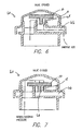
- a diaphragm assembly 10 is schematically shown as part of an air admittance vent 60.
- the air admittance vent includes a cap 62 and a base 64.
- the base 64 connects to the PDWS (not shown) and includes a channel 66 through which ambient air is allowed to enter the PDWS.
- the diaphragm assembly 10 rests on the base 64 with the stem 18 in the air admittance vent opening 68.
- the diaphragm assembly 10 is shown in the open position, while in Fig. 7 the diaphragm assembly 10 is shown in the closed position.
- the diaphragm assembly 10 allows ambient air to enter through the channel 66 and into the PDWS. This occurs when the pressure in the PDWS is less than the pressure in the ambient atmosphere.
- the diaphragm assembly 10 is caused to be in the closed position when the pressure in the PDWS is greater than the ambient atmospheric pressure.
- the stem 18 is forced down into the air admittance vent opening 68, and the annular washer (14 of Fig. 5) forms a seal with the rim of the air admittance vent opening 68, thus preventing gases and fluids in the PDWS from escaping into the ambient atmosphere around the air admittance vent
Landscapes
- Engineering & Computer Science (AREA)
- Public Health (AREA)
- General Engineering & Computer Science (AREA)
- Health & Medical Sciences (AREA)
- Life Sciences & Earth Sciences (AREA)
- Hydrology & Water Resources (AREA)
- Structural Engineering (AREA)
- Water Supply & Treatment (AREA)
- Environmental & Geological Engineering (AREA)
- Mechanical Engineering (AREA)
- Diaphragms And Bellows (AREA)
- Self-Closing Valves And Venting Or Aerating Valves (AREA)
- Measuring Fluid Pressure (AREA)
- Control Of Throttle Valves Provided In The Intake System Or In The Exhaust System (AREA)
- Fluid-Driven Valves (AREA)
Applications Claiming Priority (1)
| Application Number | Priority Date | Filing Date | Title |
|---|---|---|---|
| US11/039,502 US7445022B2 (en) | 2005-01-18 | 2005-01-18 | Air admittance vent diaphragm assembly |
Publications (2)
| Publication Number | Publication Date |
|---|---|
| EP1688548A1 true EP1688548A1 (de) | 2006-08-09 |
| EP1688548B1 EP1688548B1 (de) | 2009-08-05 |
Family
ID=36190682
Family Applications (1)
| Application Number | Title | Priority Date | Filing Date |
|---|---|---|---|
| EP20060250183 Expired - Lifetime EP1688548B1 (de) | 2005-01-18 | 2006-01-14 | Membranventil-Vorrichtung zum Einlassen von Luft |
Country Status (5)
| Country | Link |
|---|---|
| US (3) | US7445022B2 (de) |
| EP (1) | EP1688548B1 (de) |
| AT (1) | ATE438764T1 (de) |
| CA (1) | CA2532944C (de) |
| DE (1) | DE602006008196D1 (de) |
Families Citing this family (12)
| Publication number | Priority date | Publication date | Assignee | Title |
|---|---|---|---|---|
| US7445022B2 (en) * | 2005-01-18 | 2008-11-04 | Ayrlett Air Valve Company, Llc | Air admittance vent diaphragm assembly |
| TWM392286U (en) * | 2010-05-03 | 2010-11-11 | Rebecca Lin Internat Corp | Checking unit and fluid unidirectional flow control valve having the same |
| US8136548B2 (en) * | 2008-08-08 | 2012-03-20 | Watertite Products, Inc. | Air admittance valve |
| EP2224066A1 (de) * | 2009-02-25 | 2010-09-01 | Studor S.A. | Entlüftungsventil |
| EP2241686B1 (de) * | 2009-04-06 | 2012-05-16 | Studor S.A. | Lufteinlassventil mit hoher Kapazität für Sanitärrohrsystem |
| US9683355B2 (en) | 2014-04-28 | 2017-06-20 | Ips Corporation | Air admittance valve |
| US10914057B2 (en) * | 2016-10-14 | 2021-02-09 | Michael Anthony Di Monte | Dual air admittance valve |
| US11993925B2 (en) * | 2015-04-23 | 2024-05-28 | Michael Anthony Di Monte | Dual air admittance valve |
| US11466442B2 (en) * | 2016-08-12 | 2022-10-11 | Oatey Co. | Air admittance valve |
| US10132356B2 (en) | 2017-02-22 | 2018-11-20 | Mijo Radocaj | Washer with step |
| US20250320925A1 (en) * | 2020-01-05 | 2025-10-16 | Michael Anthony Di Monte | Locking Mechanism for Sealing Member of Valve with Bleeding Opening |
| US12305376B2 (en) | 2023-04-17 | 2025-05-20 | Xmark SP LLC | Air admittance valve |
Citations (2)
| Publication number | Priority date | Publication date | Assignee | Title |
|---|---|---|---|---|
| US4556084A (en) * | 1982-07-29 | 1985-12-03 | Frawley Adrian J | Air admittance valve |
| US6308731B1 (en) * | 1999-06-25 | 2001-10-30 | Itz Corporation | Vent valve |
Family Cites Families (50)
| Publication number | Priority date | Publication date | Assignee | Title |
|---|---|---|---|---|
| US11239A (en) * | 1854-07-04 | Improvement in purifying oils | ||
| US485984A (en) * | 1892-11-08 | randall | ||
| US59364A (en) | 1866-11-06 | Improvement in pumps | ||
| US2732856A (en) * | 1956-01-31 | Vacuum vent valve | ||
| US953330A (en) * | 1908-10-12 | 1910-03-29 | Byron E Van Auken | Mechanism for discharging water of condensation from steam-heating systems. |
| US1485508A (en) * | 1922-05-11 | 1924-03-04 | Ohio Brass Co | Valve |
| US1608379A (en) * | 1925-11-09 | 1926-11-23 | Romort Mfg Co | Faucet |
| US1793825A (en) * | 1928-07-14 | 1931-02-24 | Central Valve Mfg Co | Valve |
| US2074329A (en) | 1935-09-30 | 1937-03-23 | Earl R Gieseman | Vent mechanism |
| US2621017A (en) * | 1947-10-22 | 1952-12-09 | Union Steam Pump Company | Packed valve |
| DE969650C (de) | 1951-12-16 | 1958-06-26 | Triton Belco Ag | Vorrichtung zur Belueftung von insbesondere Hausinstallations-Wasserleitungen |
| US2807277A (en) | 1952-09-18 | 1957-09-24 | Bailey Lloyd Earl | Oil well pump valve |
| GB901978A (en) | 1957-11-23 | 1962-07-25 | Gen Motors Ltd | Improvements in or relating to closure caps for liquid receptacles |
| US3145724A (en) | 1960-11-14 | 1964-08-25 | Harry Karp | Vacuum breaking device |
| US3394732A (en) * | 1965-04-26 | 1968-07-30 | Protectoseal Co | Valve seal |
| US3542059A (en) | 1968-10-01 | 1970-11-24 | Jay L Blanchard | Drainage valve |
| GB1302631A (de) | 1970-06-09 | 1973-01-10 | ||
| SE377146B (de) * | 1973-10-15 | 1975-06-23 | Ba Installationsutveckling Ab | |
| US4181146A (en) | 1977-07-21 | 1980-01-01 | Luigi Goglio | Two-way valve closing at balanced pressure condition |
| AU511957B3 (en) | 1979-06-26 | 1980-09-11 | J R Kuykendall | Tank vent pipe and valves |
| US4340474A (en) | 1979-09-29 | 1982-07-20 | Johnston Ian R W | Converging flow filter |
| GB2059289B (en) | 1979-09-29 | 1983-08-24 | Johnston I R W | Converging flow separator |
| DE3008002A1 (de) | 1980-03-01 | 1981-09-10 | Reutter GmbH Metallwarenfabrik, 7050 Waiblingen | Verschlussdeckel insbesondere fuer einen kraftfahrzeugkuehler |
| GB2088023A (en) | 1980-05-02 | 1982-06-03 | Plastiers Ltd | Anti-syphon valves |
| US4414997A (en) | 1980-06-27 | 1983-11-15 | Jacobson Jeff A | Siphon |
| DE3276875D1 (en) * | 1981-02-21 | 1987-09-03 | Mcalpine & Co Ltd | Improvements in or relating to relief valves for sanitation systems or the like |
| US4502502A (en) | 1982-09-22 | 1985-03-05 | C. R. Bard, Inc. | Overpressure safety valve |
| US4513784A (en) | 1984-04-18 | 1985-04-30 | General Motors Corporation | Check valve assembly |
| US4683910A (en) | 1984-05-04 | 1987-08-04 | Mks Instruments, Inc. | High-speed protective check valving for pressure transducers and the like |
| US4665943A (en) | 1986-02-14 | 1987-05-19 | Swagelok Company | Poppet valve |
| GB2209583B (en) | 1987-09-07 | 1992-05-06 | G I Marketing C C | Plumbing arrangement for venting waste pipes connected to lavatory pans |
| US4991623A (en) | 1989-01-26 | 1991-02-12 | Ericson Kurt Sture Birger | Automatic air valves for ducts |
| ZA905617B (en) | 1989-04-20 | 1992-06-24 | Ian Fraser Johnston | Air pressure control valve |
| US5048560A (en) * | 1989-12-12 | 1991-09-17 | L&J Engineering Inc. | Sealing valve assembly |
| US5067449A (en) | 1991-04-12 | 1991-11-26 | Tecumseh Products Company | Fitted crankcase breather valve assembly |
| US5129426A (en) | 1991-05-13 | 1992-07-14 | Vernay Laboratories, Inc. | Tube mounted check valve |
| ZA935425B (en) | 1992-07-28 | 1994-02-16 | Ian Fraser-Johnston | Valve |
| US5273068A (en) | 1993-04-20 | 1993-12-28 | Duren Gary S | Air admittance valve for resisting high internal pressure |
| JP2810302B2 (ja) | 1993-10-01 | 1998-10-15 | ティーディーケイ株式会社 | 小型ポンプ |
| SE9502279L (sv) * | 1995-06-22 | 1996-07-22 | Durgo Ab | Återsugningsförhindrande ventilanordning |
| US5725099A (en) * | 1996-03-01 | 1998-03-10 | Studor Trading Ltd. | Vacuum breaker vent valve packaging and installation system |
| US5897305A (en) | 1996-08-08 | 1999-04-27 | Roddis; Gravatt Keith | Valve assembly for compressors |
| CA2209163C (en) * | 1997-06-27 | 2004-09-21 | Prism Integrated Solutions Inc. | Breather valve |
| US5996563A (en) | 1998-07-16 | 1999-12-07 | Liao; Jun-Yao | Air intake device |
| EP1026329A1 (de) * | 1999-02-03 | 2000-08-09 | Kurt Sture Birger Ericson | Lufteinlassventil für ein Abwasserleitungssystem |
| US6415816B1 (en) * | 2000-08-31 | 2002-07-09 | Cherne Industries Incorporated | Air admittance valve assembly |
| KR100442379B1 (ko) * | 2001-10-15 | 2004-07-30 | 엘지전자 주식회사 | 왕복동식 압축기의 가스 흡입장치 |
| US7422030B2 (en) * | 2004-07-15 | 2008-09-09 | Cherne Industries Incorporated | Air admittance valve assembly |
| US7445022B2 (en) * | 2005-01-18 | 2008-11-04 | Ayrlett Air Valve Company, Llc | Air admittance vent diaphragm assembly |
| US7395835B1 (en) * | 2005-02-16 | 2008-07-08 | Rectorseal Corporation | Air admittance valve |
-
2005
- 2005-01-18 US US11/039,502 patent/US7445022B2/en active Active
-
2006
- 2006-01-13 CA CA 2532944 patent/CA2532944C/en not_active Expired - Fee Related
- 2006-01-14 EP EP20060250183 patent/EP1688548B1/de not_active Expired - Lifetime
- 2006-01-14 AT AT06250183T patent/ATE438764T1/de not_active IP Right Cessation
- 2006-01-14 DE DE200660008196 patent/DE602006008196D1/de not_active Expired - Lifetime
- 2006-04-28 US US11/413,806 patent/US20060191576A1/en not_active Abandoned
-
2008
- 2008-08-27 US US12/199,734 patent/US7971605B2/en not_active Expired - Fee Related
Patent Citations (2)
| Publication number | Priority date | Publication date | Assignee | Title |
|---|---|---|---|---|
| US4556084A (en) * | 1982-07-29 | 1985-12-03 | Frawley Adrian J | Air admittance valve |
| US6308731B1 (en) * | 1999-06-25 | 2001-10-30 | Itz Corporation | Vent valve |
Also Published As
| Publication number | Publication date |
|---|---|
| ATE438764T1 (de) | 2009-08-15 |
| DE602006008196D1 (de) | 2009-09-17 |
| US20060191576A1 (en) | 2006-08-31 |
| CA2532944A1 (en) | 2006-07-18 |
| US20080314460A1 (en) | 2008-12-25 |
| CA2532944C (en) | 2011-08-02 |
| EP1688548B1 (de) | 2009-08-05 |
| US7971605B2 (en) | 2011-07-05 |
| US20060157118A1 (en) | 2006-07-20 |
| US7445022B2 (en) | 2008-11-04 |
Similar Documents
| Publication | Publication Date | Title |
|---|---|---|
| US7971605B2 (en) | Air admittance vent diaphragm assembly | |
| US8136548B2 (en) | Air admittance valve | |
| CN102333922B (zh) | 进气阀 | |
| US9816261B2 (en) | Seals for closet collars | |
| CN101730652B (zh) | 喷雾剂阀 | |
| US6415816B1 (en) | Air admittance valve assembly | |
| US8001991B2 (en) | Vent valve for the fuel tank of a motor vehicle | |
| JP7049483B2 (ja) | 弁装置 | |
| US3949780A (en) | Two piece check valve | |
| US7270146B1 (en) | Air vent valve | |
| JP2005261512A (ja) | 内視鏡の操作弁 | |
| KR101798610B1 (ko) | 위생설비의 배수배관용 통기 밸브 조립체 | |
| EP2241686B1 (de) | Lufteinlassventil mit hoher Kapazität für Sanitärrohrsystem | |
| JP2020101203A (ja) | 吸排気弁及び排水管構造 | |
| JPH08200034A (ja) | ブリーザ | |
| US20260139750A1 (en) | Air admittance valve assembly | |
| TW202430798A (zh) | 進氣閥總成 | |
| EP0505107B1 (de) | Ventil zum Einlassen von Luft | |
| US20080029160A1 (en) | Vacuum breaking device | |
| HK1164954B (en) | Air admittance valve |
Legal Events
| Date | Code | Title | Description |
|---|---|---|---|
| PUAI | Public reference made under article 153(3) epc to a published international application that has entered the european phase |
Free format text: ORIGINAL CODE: 0009012 |
|
| AK | Designated contracting states |
Kind code of ref document: A1 Designated state(s): AT BE BG CH CY CZ DE DK EE ES FI FR GB GR HU IE IS IT LI LT LU LV MC NL PL PT RO SE SI SK TR |
|
| AX | Request for extension of the european patent |
Extension state: AL BA HR MK YU |
|
| 17P | Request for examination filed |
Effective date: 20070202 |
|
| AKX | Designation fees paid |
Designated state(s): AT BE BG CH CY CZ DE DK EE ES FI FR GB GR HU IE IS IT LI LT LU LV MC NL PL PT RO SE SI SK TR |
|
| GRAP | Despatch of communication of intention to grant a patent |
Free format text: ORIGINAL CODE: EPIDOSNIGR1 |
|
| GRAS | Grant fee paid |
Free format text: ORIGINAL CODE: EPIDOSNIGR3 |
|
| GRAA | (expected) grant |
Free format text: ORIGINAL CODE: 0009210 |
|
| AK | Designated contracting states |
Kind code of ref document: B1 Designated state(s): AT BE BG CH CY CZ DE DK EE ES FI FR GB GR HU IE IS IT LI LT LU LV MC NL PL PT RO SE SI SK TR |
|
| REG | Reference to a national code |
Ref country code: GB Ref legal event code: FG4D |
|
| REG | Reference to a national code |
Ref country code: CH Ref legal event code: EP |
|
| REG | Reference to a national code |
Ref country code: IE Ref legal event code: FG4D |
|
| REF | Corresponds to: |
Ref document number: 602006008196 Country of ref document: DE Date of ref document: 20090917 Kind code of ref document: P |
|
| LTIE | Lt: invalidation of european patent or patent extension |
Effective date: 20090805 |
|
| PG25 | Lapsed in a contracting state [announced via postgrant information from national office to epo] |
Ref country code: IS Free format text: LAPSE BECAUSE OF FAILURE TO SUBMIT A TRANSLATION OF THE DESCRIPTION OR TO PAY THE FEE WITHIN THE PRESCRIBED TIME-LIMIT Effective date: 20091205 Ref country code: AT Free format text: LAPSE BECAUSE OF FAILURE TO SUBMIT A TRANSLATION OF THE DESCRIPTION OR TO PAY THE FEE WITHIN THE PRESCRIBED TIME-LIMIT Effective date: 20090805 Ref country code: FI Free format text: LAPSE BECAUSE OF FAILURE TO SUBMIT A TRANSLATION OF THE DESCRIPTION OR TO PAY THE FEE WITHIN THE PRESCRIBED TIME-LIMIT Effective date: 20090805 Ref country code: ES Free format text: LAPSE BECAUSE OF FAILURE TO SUBMIT A TRANSLATION OF THE DESCRIPTION OR TO PAY THE FEE WITHIN THE PRESCRIBED TIME-LIMIT Effective date: 20091116 Ref country code: SE Free format text: LAPSE BECAUSE OF FAILURE TO SUBMIT A TRANSLATION OF THE DESCRIPTION OR TO PAY THE FEE WITHIN THE PRESCRIBED TIME-LIMIT Effective date: 20090805 Ref country code: LT Free format text: LAPSE BECAUSE OF FAILURE TO SUBMIT A TRANSLATION OF THE DESCRIPTION OR TO PAY THE FEE WITHIN THE PRESCRIBED TIME-LIMIT Effective date: 20090805 |
|
| NLV1 | Nl: lapsed or annulled due to failure to fulfill the requirements of art. 29p and 29m of the patents act | ||
| PG25 | Lapsed in a contracting state [announced via postgrant information from national office to epo] |
Ref country code: PL Free format text: LAPSE BECAUSE OF FAILURE TO SUBMIT A TRANSLATION OF THE DESCRIPTION OR TO PAY THE FEE WITHIN THE PRESCRIBED TIME-LIMIT Effective date: 20090805 Ref country code: SI Free format text: LAPSE BECAUSE OF FAILURE TO SUBMIT A TRANSLATION OF THE DESCRIPTION OR TO PAY THE FEE WITHIN THE PRESCRIBED TIME-LIMIT Effective date: 20090805 Ref country code: NL Free format text: LAPSE BECAUSE OF FAILURE TO SUBMIT A TRANSLATION OF THE DESCRIPTION OR TO PAY THE FEE WITHIN THE PRESCRIBED TIME-LIMIT Effective date: 20090805 Ref country code: LV Free format text: LAPSE BECAUSE OF FAILURE TO SUBMIT A TRANSLATION OF THE DESCRIPTION OR TO PAY THE FEE WITHIN THE PRESCRIBED TIME-LIMIT Effective date: 20090805 |
|
| PG25 | Lapsed in a contracting state [announced via postgrant information from national office to epo] |
Ref country code: PT Free format text: LAPSE BECAUSE OF FAILURE TO SUBMIT A TRANSLATION OF THE DESCRIPTION OR TO PAY THE FEE WITHIN THE PRESCRIBED TIME-LIMIT Effective date: 20091205 Ref country code: BG Free format text: LAPSE BECAUSE OF FAILURE TO SUBMIT A TRANSLATION OF THE DESCRIPTION OR TO PAY THE FEE WITHIN THE PRESCRIBED TIME-LIMIT Effective date: 20091105 |
|
| PG25 | Lapsed in a contracting state [announced via postgrant information from national office to epo] |
Ref country code: RO Free format text: LAPSE BECAUSE OF FAILURE TO SUBMIT A TRANSLATION OF THE DESCRIPTION OR TO PAY THE FEE WITHIN THE PRESCRIBED TIME-LIMIT Effective date: 20090805 Ref country code: DK Free format text: LAPSE BECAUSE OF FAILURE TO SUBMIT A TRANSLATION OF THE DESCRIPTION OR TO PAY THE FEE WITHIN THE PRESCRIBED TIME-LIMIT Effective date: 20090805 Ref country code: CZ Free format text: LAPSE BECAUSE OF FAILURE TO SUBMIT A TRANSLATION OF THE DESCRIPTION OR TO PAY THE FEE WITHIN THE PRESCRIBED TIME-LIMIT Effective date: 20090805 Ref country code: EE Free format text: LAPSE BECAUSE OF FAILURE TO SUBMIT A TRANSLATION OF THE DESCRIPTION OR TO PAY THE FEE WITHIN THE PRESCRIBED TIME-LIMIT Effective date: 20090805 |
|
| PG25 | Lapsed in a contracting state [announced via postgrant information from national office to epo] |
Ref country code: SK Free format text: LAPSE BECAUSE OF FAILURE TO SUBMIT A TRANSLATION OF THE DESCRIPTION OR TO PAY THE FEE WITHIN THE PRESCRIBED TIME-LIMIT Effective date: 20090805 |
|
| PLBE | No opposition filed within time limit |
Free format text: ORIGINAL CODE: 0009261 |
|
| STAA | Information on the status of an ep patent application or granted ep patent |
Free format text: STATUS: NO OPPOSITION FILED WITHIN TIME LIMIT |
|
| PG25 | Lapsed in a contracting state [announced via postgrant information from national office to epo] |
Ref country code: BE Free format text: LAPSE BECAUSE OF FAILURE TO SUBMIT A TRANSLATION OF THE DESCRIPTION OR TO PAY THE FEE WITHIN THE PRESCRIBED TIME-LIMIT Effective date: 20090805 |
|
| 26N | No opposition filed |
Effective date: 20100507 |
|
| PG25 | Lapsed in a contracting state [announced via postgrant information from national office to epo] |
Ref country code: MC Free format text: LAPSE BECAUSE OF NON-PAYMENT OF DUE FEES Effective date: 20100131 |
|
| REG | Reference to a national code |
Ref country code: CH Ref legal event code: PL |
|
| PG25 | Lapsed in a contracting state [announced via postgrant information from national office to epo] |
Ref country code: GR Free format text: LAPSE BECAUSE OF FAILURE TO SUBMIT A TRANSLATION OF THE DESCRIPTION OR TO PAY THE FEE WITHIN THE PRESCRIBED TIME-LIMIT Effective date: 20091106 Ref country code: LI Free format text: LAPSE BECAUSE OF NON-PAYMENT OF DUE FEES Effective date: 20100131 Ref country code: CH Free format text: LAPSE BECAUSE OF NON-PAYMENT OF DUE FEES Effective date: 20100131 |
|
| PG25 | Lapsed in a contracting state [announced via postgrant information from national office to epo] |
Ref country code: IE Free format text: LAPSE BECAUSE OF NON-PAYMENT OF DUE FEES Effective date: 20100114 |
|
| PG25 | Lapsed in a contracting state [announced via postgrant information from national office to epo] |
Ref country code: IT Free format text: LAPSE BECAUSE OF FAILURE TO SUBMIT A TRANSLATION OF THE DESCRIPTION OR TO PAY THE FEE WITHIN THE PRESCRIBED TIME-LIMIT Effective date: 20090805 |
|
| PGFP | Annual fee paid to national office [announced via postgrant information from national office to epo] |
Ref country code: FR Payment date: 20120217 Year of fee payment: 7 |
|
| PGFP | Annual fee paid to national office [announced via postgrant information from national office to epo] |
Ref country code: DE Payment date: 20120131 Year of fee payment: 7 |
|
| PGFP | Annual fee paid to national office [announced via postgrant information from national office to epo] |
Ref country code: GB Payment date: 20120201 Year of fee payment: 7 |
|
| PG25 | Lapsed in a contracting state [announced via postgrant information from national office to epo] |
Ref country code: CY Free format text: LAPSE BECAUSE OF FAILURE TO SUBMIT A TRANSLATION OF THE DESCRIPTION OR TO PAY THE FEE WITHIN THE PRESCRIBED TIME-LIMIT Effective date: 20090805 |
|
| PG25 | Lapsed in a contracting state [announced via postgrant information from national office to epo] |
Ref country code: LU Free format text: LAPSE BECAUSE OF NON-PAYMENT OF DUE FEES Effective date: 20100114 Ref country code: HU Free format text: LAPSE BECAUSE OF FAILURE TO SUBMIT A TRANSLATION OF THE DESCRIPTION OR TO PAY THE FEE WITHIN THE PRESCRIBED TIME-LIMIT Effective date: 20100206 |
|
| PG25 | Lapsed in a contracting state [announced via postgrant information from national office to epo] |
Ref country code: TR Free format text: LAPSE BECAUSE OF FAILURE TO SUBMIT A TRANSLATION OF THE DESCRIPTION OR TO PAY THE FEE WITHIN THE PRESCRIBED TIME-LIMIT Effective date: 20090805 |
|
| GBPC | Gb: european patent ceased through non-payment of renewal fee |
Effective date: 20130114 |
|
| REG | Reference to a national code |
Ref country code: FR Ref legal event code: ST Effective date: 20130930 |
|
| PG25 | Lapsed in a contracting state [announced via postgrant information from national office to epo] |
Ref country code: DE Free format text: LAPSE BECAUSE OF NON-PAYMENT OF DUE FEES Effective date: 20130801 |
|
| REG | Reference to a national code |
Ref country code: DE Ref legal event code: R119 Ref document number: 602006008196 Country of ref document: DE Effective date: 20130801 |
|
| PG25 | Lapsed in a contracting state [announced via postgrant information from national office to epo] |
Ref country code: FR Free format text: LAPSE BECAUSE OF NON-PAYMENT OF DUE FEES Effective date: 20130131 Ref country code: GB Free format text: LAPSE BECAUSE OF NON-PAYMENT OF DUE FEES Effective date: 20130114 |