EP1688687A1 - Kühlvorrichtung - Google Patents
Kühlvorrichtung Download PDFInfo
- Publication number
- EP1688687A1 EP1688687A1 EP04792968A EP04792968A EP1688687A1 EP 1688687 A1 EP1688687 A1 EP 1688687A1 EP 04792968 A EP04792968 A EP 04792968A EP 04792968 A EP04792968 A EP 04792968A EP 1688687 A1 EP1688687 A1 EP 1688687A1
- Authority
- EP
- European Patent Office
- Prior art keywords
- cooling
- cooler
- cooled
- cooling fan
- cooling device
- Prior art date
- Legal status (The legal status is an assumption and is not a legal conclusion. Google has not performed a legal analysis and makes no representation as to the accuracy of the status listed.)
- Withdrawn
Links
Images





Classifications
-
- F—MECHANICAL ENGINEERING; LIGHTING; HEATING; WEAPONS; BLASTING
- F25—REFRIGERATION OR COOLING; COMBINED HEATING AND REFRIGERATION SYSTEMS; HEAT PUMP SYSTEMS; MANUFACTURE OR STORAGE OF ICE; LIQUEFACTION SOLIDIFICATION OF GASES
- F25D—REFRIGERATORS; COLD ROOMS; ICE-BOXES; COOLING OR FREEZING APPARATUS NOT OTHERWISE PROVIDED FOR
- F25D17/00—Arrangements for circulating cooling fluids; Arrangements for circulating gas, e.g. air, within refrigerated spaces
- F25D17/04—Arrangements for circulating cooling fluids; Arrangements for circulating gas, e.g. air, within refrigerated spaces for circulating air, e.g. by convection
- F25D17/06—Arrangements for circulating cooling fluids; Arrangements for circulating gas, e.g. air, within refrigerated spaces for circulating air, e.g. by convection by forced circulation
- F25D17/062—Arrangements for circulating cooling fluids; Arrangements for circulating gas, e.g. air, within refrigerated spaces for circulating air, e.g. by convection by forced circulation in household refrigerators
-
- F—MECHANICAL ENGINEERING; LIGHTING; HEATING; WEAPONS; BLASTING
- F25—REFRIGERATION OR COOLING; COMBINED HEATING AND REFRIGERATION SYSTEMS; HEAT PUMP SYSTEMS; MANUFACTURE OR STORAGE OF ICE; LIQUEFACTION SOLIDIFICATION OF GASES
- F25D—REFRIGERATORS; COLD ROOMS; ICE-BOXES; COOLING OR FREEZING APPARATUS NOT OTHERWISE PROVIDED FOR
- F25D13/00—Stationary devices, e.g. cold-rooms
- F25D13/06—Stationary devices, e.g. cold-rooms with conveyors carrying articles to be cooled through the cooling space
- F25D13/067—Stationary devices, e.g. cold-rooms with conveyors carrying articles to be cooled through the cooling space with circulation of gaseous cooling fluid
-
- F—MECHANICAL ENGINEERING; LIGHTING; HEATING; WEAPONS; BLASTING
- F25—REFRIGERATION OR COOLING; COMBINED HEATING AND REFRIGERATION SYSTEMS; HEAT PUMP SYSTEMS; MANUFACTURE OR STORAGE OF ICE; LIQUEFACTION SOLIDIFICATION OF GASES
- F25D—REFRIGERATORS; COLD ROOMS; ICE-BOXES; COOLING OR FREEZING APPARATUS NOT OTHERWISE PROVIDED FOR
- F25D17/00—Arrangements for circulating cooling fluids; Arrangements for circulating gas, e.g. air, within refrigerated spaces
- F25D17/04—Arrangements for circulating cooling fluids; Arrangements for circulating gas, e.g. air, within refrigerated spaces for circulating air, e.g. by convection
- F25D17/06—Arrangements for circulating cooling fluids; Arrangements for circulating gas, e.g. air, within refrigerated spaces for circulating air, e.g. by convection by forced circulation
- F25D17/067—Evaporator fan units
-
- F—MECHANICAL ENGINEERING; LIGHTING; HEATING; WEAPONS; BLASTING
- F25—REFRIGERATION OR COOLING; COMBINED HEATING AND REFRIGERATION SYSTEMS; HEAT PUMP SYSTEMS; MANUFACTURE OR STORAGE OF ICE; LIQUEFACTION SOLIDIFICATION OF GASES
- F25D—REFRIGERATORS; COLD ROOMS; ICE-BOXES; COOLING OR FREEZING APPARATUS NOT OTHERWISE PROVIDED FOR
- F25D17/00—Arrangements for circulating cooling fluids; Arrangements for circulating gas, e.g. air, within refrigerated spaces
- F25D17/04—Arrangements for circulating cooling fluids; Arrangements for circulating gas, e.g. air, within refrigerated spaces for circulating air, e.g. by convection
- F25D17/06—Arrangements for circulating cooling fluids; Arrangements for circulating gas, e.g. air, within refrigerated spaces for circulating air, e.g. by convection by forced circulation
-
- F—MECHANICAL ENGINEERING; LIGHTING; HEATING; WEAPONS; BLASTING
- F25—REFRIGERATION OR COOLING; COMBINED HEATING AND REFRIGERATION SYSTEMS; HEAT PUMP SYSTEMS; MANUFACTURE OR STORAGE OF ICE; LIQUEFACTION SOLIDIFICATION OF GASES
- F25D—REFRIGERATORS; COLD ROOMS; ICE-BOXES; COOLING OR FREEZING APPARATUS NOT OTHERWISE PROVIDED FOR
- F25D2317/00—Details or arrangements for circulating cooling fluids; Details or arrangements for circulating gas, e.g. air, within refrigerated spaces, not provided for in other groups of this subclass
- F25D2317/06—Details or arrangements for circulating cooling fluids; Details or arrangements for circulating gas, e.g. air, within refrigerated spaces, not provided for in other groups of this subclass with forced air circulation
- F25D2317/068—Details or arrangements for circulating cooling fluids; Details or arrangements for circulating gas, e.g. air, within refrigerated spaces, not provided for in other groups of this subclass with forced air circulation characterised by the fans
- F25D2317/0681—Details thereof
-
- F—MECHANICAL ENGINEERING; LIGHTING; HEATING; WEAPONS; BLASTING
- F25—REFRIGERATION OR COOLING; COMBINED HEATING AND REFRIGERATION SYSTEMS; HEAT PUMP SYSTEMS; MANUFACTURE OR STORAGE OF ICE; LIQUEFACTION SOLIDIFICATION OF GASES
- F25D—REFRIGERATORS; COLD ROOMS; ICE-BOXES; COOLING OR FREEZING APPARATUS NOT OTHERWISE PROVIDED FOR
- F25D2317/00—Details or arrangements for circulating cooling fluids; Details or arrangements for circulating gas, e.g. air, within refrigerated spaces, not provided for in other groups of this subclass
- F25D2317/06—Details or arrangements for circulating cooling fluids; Details or arrangements for circulating gas, e.g. air, within refrigerated spaces, not provided for in other groups of this subclass with forced air circulation
- F25D2317/068—Details or arrangements for circulating cooling fluids; Details or arrangements for circulating gas, e.g. air, within refrigerated spaces, not provided for in other groups of this subclass with forced air circulation characterised by the fans
- F25D2317/0682—Two or more fans
-
- F—MECHANICAL ENGINEERING; LIGHTING; HEATING; WEAPONS; BLASTING
- F25—REFRIGERATION OR COOLING; COMBINED HEATING AND REFRIGERATION SYSTEMS; HEAT PUMP SYSTEMS; MANUFACTURE OR STORAGE OF ICE; LIQUEFACTION SOLIDIFICATION OF GASES
- F25D—REFRIGERATORS; COLD ROOMS; ICE-BOXES; COOLING OR FREEZING APPARATUS NOT OTHERWISE PROVIDED FOR
- F25D2500/00—Problems to be solved
- F25D2500/02—Geometry problems
Definitions
- the present invention relates to a cooling device for cooling an object to be cooled without using a forced cold air circulating system that circulates cold air forcibly.
- a conventional forced cold air circulating system has circulated cold air by sending with a fan the air cooled by a cooler such as a cooling coil forcibly from a blowing port into a cooling chamber in which an object to be cooled is placed, withdrawing the cold air whose temperature has risen due to heat exchange with the object to be cooled from a suction port to the cooler, cooling the air with the cooler again and sending the air to the cooling chamber with the fan.
- a cooler such as a cooling coil forcibly from a blowing port into a cooling chamber in which an object to be cooled is placed
- withdrawing the cold air whose temperature has risen due to heat exchange with the object to be cooled from a suction port to the cooler cooling the air with the cooler again and sending the air to the cooling chamber with the fan.
- the cold air is blown against the surface of the object to be cooled, thereby cooling the object while removing moisture as well as hot air from the object.
- the forced cold air circulating system has the following problems. 1) As the object to be cooled dries, its natural moisture is taken away. In the case where the object to be cooled is a food material, its taste and quality deteriorate. 2) The moisture is taken from the object to be cooled, so that, in a freezing temperature range, ice crystals attract each other and grow into larger crystals, thus swelling and also engulfing intracellular elements of the object to be cooled, resulting in degeneration of the object. 3) Since the circulating path of the cold air is fixed, the time during which the air is in contact with the object to be cooled is short, making it difficult to conduct quick cooling.
- JP 2852300 B Patent document 1
- JP 3366977 B Patent document 2
- a cooler is provided on a side of one wall in a chamber sealed by a heat-insulating housing, a front surface of the cooler is provided with a cooling fan, a space in front of the cooling fan serves as a cooling chamber, and cooled air present near the cooler is withdrawn from a back surface of the cooling fan and allowed to flow into the cooling chamber.
- the cooled air in the cooling chamber is not circulated forcibly to the cooler, and a heat exchange by collision of molecules between the cooling chamber and a cooling portion including the cooler is carried out at an interface between air layers of the cooling portion and the cooling chamber.
- the cooling chamber has a saturated water vapor pressure and is not dry, so that a slight amount of moisture on the surface of the object to be cooled is frozen instantaneously to form a thin ice barrier over the entire surface. This makes it possible to keep the ice crystals in the object to be cooled microscopically, thereby avoiding the degeneration of the object.
- a gap between a back surface of the cooling coil serving as the cooler and the wall surface of the chamber range from 20 to 50 mm.
- a gap smaller than the above does not allow a sufficient amount of cold air to be withdrawn, whereas an excessively large gap causes the cold air to be distributed in that gap, preventing the guidance of the cold air to the space behind the fan.
- the studies conducted by the inventors of the present invention have revealed not only that the gap with the above-noted numerical range does not produce a sufficient cooling effect but also that there is a condition that should be satisfied in order to provide a practical cooling device. In other words, there is a problem that it is impossible or insufficient for achieving a cooling device at a practical level to satisfy only the condition described in the conventional documents mentioned above.
- the present invention was made with the foregoing problems in mind, and the problem to be solved by the present invention is to provide a cooling device at a practical level and a cooling device capable of achieving a sufficient cooling effect, in a cooling device for cooling an object to be cooled without using a forced cold air circulating system that circulates cold air forcibly.
- the present invention is characterized by a cooling device including a cooler provided in an interior that is insulated adiabatically from an exterior, a cooling fan disposed on a front surface of the cooler, and a cooling chamber that is defined by a space in front of the cooling fan and in which an object to be cooled is placed.
- the cooling device draws cooled air behind the cooling fan with the fan and allows the cooled air to flow into the cooling chamber.
- a /D 1/2 to 1/4 is satisfied, where a indicates a dimension of a gap between the cooler and the cooling fan along a front-back direction and D indicates a diameter of the cooling fan.
- the second aspect of the invention is a cooling device including a cooler provided in an interior that is insulated adiabatically from an exterior, a cooling fan disposed on a front surface of the cooler, and a cooling chamber that is defined by a space in front of the cooling fan and in which an object to be cooled is placed.
- the cooling device draws cooled air behind the cooling fan with the cooling fan and allows the cooled air to flow into the cooling chamber.
- a dimension of a gap between the cooler and a wall surface on a back surface side of the cooler is set to be larger than 50 mm.
- the above-described second aspect of the invention is characterized in that a lateral surface of the cooler is covered with a control plate so as to prevent substantially air from moving in and out through the lateral surface of the cooler.
- the number of revolutions of the cooling fan can be made adjustable. Preferably, the number of revolutions can be 1200 to 2100 rpm.
- the cooling device further can include in the cooling chamber a vibration driving portion for vibrating a placement stage on which the object to be cooled is placed.
- the coolers are provided so as to face each other with the cooling chamber interposed therebetween, and the cooling fans provided respectively on the front surfaces of the facing coolers can be offset so as not to face each other.
- the number of the cooling fans provided on the front surface of the cooler is more than one, and when the front surface of the cooler is divided virtually into a plurality of blocks, the cooling fans can be arranged on the front surface corresponding to blocks selected in a staggered manner. Also, it is appropriate that a rotation of the cooling fan is set to be counterclockwise in the Northern Hemisphere and clockwise in the Southern Hemisphere.
- the speed of the air flowing in a cooling chamber is set to low, the generation of a flow passing through a cooler is minimized, and frost is made to form in the cooling chamber forward of a cooling fan and prevented from forming on the cooler.
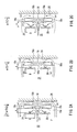
- FIGs. 1A to 1B are sectional views showing an internal structure of a cooling device according to the first embodiment of the present invention.
- a cooling device 10 has an interior 16 that is surrounded by a heat-insulating wall 12 so as to be insulated adiabatically from the exterior.
- One lateral surface (front surface) of the interior 16 is provided with a door 14 that can be opened and closed freely for carrying an object to be cooled in and out.
- a cooler 18 is provided in the interior 16.
- An overall shape of the cooler 18 usually is a rectangle (including a square) viewed from the front surface thereof.
- the cooler 18 is connected with a compressor and a condenser that are disposed externally (not shown), and a refrigerant circulates therethrough.
- the cooler 18 serves as an evaporator for cooling the ambient air by evaporation of the refrigerant and can be constituted by, for example, cooling coils around which cooling fins are formed.
- the air can move between the cooling fins of the adjacent cooling coils in any of a vertical direction, a front-back direction and a transverse direction and basically can flow into and out of the cooler 18 from all of the four side directions of a back surface; both lateral surfaces and a front surface of the cooler 18.
- a front surface of the cooler 18 is provided with cooling fans 20 having a motor. It is appropriate that a plurality of the cooling fans 20 be provided. In this example, a pair of the cooling fans 20 are arranged diagonally opposite to each other when viewed from the front surface of the cooler 18. These cooling fans 20 are not provided with a bell mouth, which conventionally has been used in general for increasing the volume of air flow.
- a space in the interior 16 in front of the cooling fans 20 serves as a cooling chamber 22. Both lateral surfaces of the interior 16 are provided with guide rails 23, along which a plurality of trays 24 are disposed. An object to be cooled can be placed on these trays 24.
- the following is important for enhancing a heat exchange efficiency. That is, circulation is not caused forcibly between a cooling portion including the cooler 18 and the cooling chamber 22, and a low-speed air turbulence is generated in the cooling chamber 22. Further, the generation of a flow passing through the cooler 18 is minimized so as to prevent frost from forming on the cooler 18, thus causing a sufficient heat exchange between the cooling chamber 22 and the cooling portion.
- the inventors of the present invention have found that it is necessary to set appropriate numerical values of 1) a dimension of a gap between the cooler 18 and the cooling fan 20 along a front-back direction, 2) a dimension of a gap between the cooler 18 and a wall surface 26 facing a side of the cooler 18 opposite to the cooling fan 20, namely, a back surface side of the cooler 18 and 3) the number of revolutions of the cooling fan. In the following, they will be studied sequentially.
- the gap between the cooler 18 and the cooling fan 20 along the front-back direction is not reduced but set to a predetermined range.
- the air flow generated in the cooling portion can be a flow that comes from the side of the cooling chamber 22, moves around the back surface 18b and the both lateral surfaces 18c, 18c of the cooler 18 and flows into the cooling chamber 22 (represented by ( ⁇ ) in the figure), a flow that-comes from the side of the cooling chamber 22, goes around a space behind the cooling fan 20, is drawn by the cooling fan 20 and then flows into the cooling chamber 22 again (represented by ( ⁇ ) in the figure) and a flow that is drawn from the ambient space of the cooler 18 to the cooling fan 20 (represented by ( ⁇ ) in the figure).
- the flow ( ⁇ ) and the flow ( ⁇ ) among them are distributed in good balance, whereby the air that has been warmed up by the object to be cooled and flowed from the side of the cooling chamber 22 exchanges heat with the ambient air of the cooler 18 that has been cooled by the cooler 18, and flows toward the cooling chamber 22.
- a minimal volume of the highly humid air flowing from the side of the cooling chamber 22 should enter the cooler 18, thus preventing frost from forming on the cooler 18.
- the flow ( ⁇ ) that comes from the ambient space of the cooler 18 and is drawn by the cooling fan 20 without moving around the cooler 18 is generated more than the flow ( ⁇ ) moving around the three surfaces of the both lateral surfaces 18c, 18c and the back surface 18b of the cooler 18, causing a problem that the heat exchange between the flow from the side of the cooling chamber 22 and the ambient air cooled by the cooler 18 cannot be carried out sufficiently.
- the cooling portion and the cooling chamber 22 function as if they were separated completely, resulting in a poor heat exchange efficiency.
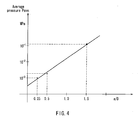
- FIG. 4 is a graph showing results of measuring a pressure of the flow generated in the cooling chamber 22 with respect to various values of a ratio a /D of the dimension a of the gap between the cooler 18 and the cooling fan 20 along the front-back direction to the diameter D of the cooling fan 20 described above.
- the pressure to the object to be cooled should neither be too large nor too small and preferably ranges from 10 gf/cm 2 to 28 gf/cm 2 .
- the cooled air sent from the cooling fan 20 to the cooling chamber 22 collides with the cooled air reflected by a wall surface that is opposed to the cooling fan 20 (the door 14 or a front surface of the tray 24 in the exemplary case of FIG. 1), turns into a turbulent state and contacts the object to be cooled.
- the pressure is oscillating or pulsing.
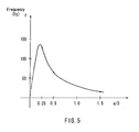
- FIG. 5 shows results of measuring the relationship between a /D and a frequency f of that pressure pulsation. If the frequency f of the pulsation is high, a heat-insulating air layer, which may be built up at an interface between the object to be cooled and the ambient air, can be removed to enhance the heat exchange rate with the object, thus achieving a high cooling effect.
- the frequency can be enhanced when a /D is in a certain range.
- a /D is in the range of 1/4 to 1/2, a fully satisfactory frequency can be achieved.
- the size of ice crystals formed on the object to be cooled was 1/5 to 1/10 of that of ice crystals formed in the case of the forced circulating system.
- FIG. 6 shows results of measuring the relationship between a /D and a relative amplitude T/P ave , which is the ratio of an amplitude T of the pressure pulsation to the average pressure P ave at the measurement point.
- T/P ave the relative amplitude of the pulsation
- the relative amplitude can be increased when a /D is in a certain range.
- a /D is in the range of 1/4 to 1/2, a fully satisfactory relative amplitude can be achieved.
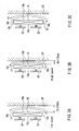
- the distance Db between the cooler 18 and the wall surface 26 on the back surface side of the cooler 18 smaller than 50 mm as shown in FIG. 3B is not preferable because a narrowing effect by this gap raises the speed of the flow ( ⁇ ) moving around the three surfaces of the both lateral surfaces 18c, 18c and the back surface 18b of the cooler 18.
- the inventors of the present invention have found that the value of the distance Db is affected by a control plate placed around the cooler 18.
- a control plate placed around the cooler 18 In the case where the both lateral surfaces 18c, 18c and the back surface 18b of the cooler 18 are covered with the control plates, it is not possible to conduct a heat exchange between the flow ( ⁇ ) and the air cooled by the cooler 18, so that a cooling effect cannot be obtained.
- the both lateral surfaces 18c, 18c and the back surface 18b are all opened, the speed of the flow ( ⁇ ) moving around these surfaces tends to increase.
- control plates 28 are placed on the both lateral surfaces 18c as shown in FIG.
- the flow ( ⁇ ) cannot conduct the heat exchange on the both lateral surfaces 18c, 18c of the cooler 18, but an increase in its speed can be suppressed. Accordingly, it is sufficient that the distance Db is set to be equal to or larger than 50 mm. On the other hand, in the case of placing no control plate 28, it is appropriate that the distance Db is set to be larger than 50 mm and preferably at least 100 mm.
- these lateral surfaces 18c can include an upper surface and a lower surface of the cooler 18. At least one of a plurality of the lateral surfaces 18c may be covered with the control plate 28.
- Db is set to be equal to or larger than 50 mm in combination with the preferable range of a/D obtained in 1) (i.e., 1/4 to 1/2), whereby the heat exchange efficiency can be enhanced further.
- a smaller average pressure indicates a lower speed of the flow from the cooler 18 toward the cooling chamber 22.
- a smaller distance Db increases the pressure, thus affecting the object to be cooled adversely.
- the pressure no longer depends on the distance Db and becomes constant. It is understood from the graph that a threshold at this time should be Db > 50 mm and preferably Db ⁇ 100 mm.
- the number of revolutions of the cooling fan 20 also influences the speed of flow in the cooling chamber 22.
- the motor driving the cooling fan 20 is controlled by an inverter.
- FIG. 8 shows the relationship between the distance a and the number of revolutions N.
- the average pressure and the speed increase exponentially with the distance a .
- the number of revolutions is reduced so as to cancel out that increase, thereby keeping the pressure and the speed not greater than predetermined values even when the distance a increases.
- the distance a and the number of revolutions N are adjusted according to an inverse exponential function as shown in FIG. 8, so that the cooling can be conducted under a similar condition even when the distance a changes to some extent. It is appropriate that the number of revolutions be adjusted in the range of 1200 to 2100 rpm.
- the relationship between the distance Db and the number of revolutions N is similar to the above. As shown in FIG. 7, the average pressure and the speed increase exponentially with a decrease in the distance Db. Thus, the number of revolutions is reduced so as to cancel out that increase, thereby keeping the pressure and the speed not greater than predetermined values even when the distance Db decreases.
- the distance Db and the number of revolutions N are adjusted according to an exponential function as shown in FIG. 9, so that the cooling can be conducted under a similar condition even when the distance Db changes to some extent. It is appropriate that the number of revolutions be adjusted in the range of 1200 to 2100 rpm. In this manner, also in the preferable ranges of a /D and Db described above, it is possible to conduct cooling in a condition closer to ideal by adjusting the number of revolutions of the cooling fan.
- FIG. 10 shows another embodiment.
- a vibration driving portion 30 further is provided for vibrating the tray 24 serving as a placement stage on which the object to be cooled is placed.
- the vibration driving portion 30 can be any suitable driving mechanisms.
- FIGs. 11A to 11B show yet another embodiment.
- one side of the interior 16 that is opposed to the door 14 is provided with the cooler 18 in the example illustrated in FIGs. 1A to 1B
- the cooler 18 can be arranged at any positions in the interior 16.
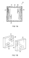
- FIGs. 11A to 11B illustrate an example in which the coolers 18 are provided on both sides of the interior 16, and thus, the cooling portions are provided on both sides of the interior 16.
- the cooling fans 20 provided on the front surface of each of the coolers 18 be offset alternately in a staggered manner, instead of facing each other.
- the rotation of the cooling fan 20 is set to be counterclockwise in the Northern Hemisphere and clockwise in the Southern Hemisphere. In this way, the cooling fan 20 can form a spiral air layer smoothly by the Coriolis force, thus achieving an improved energy efficiency.
- the cooling device 10 is not limited to a device forming a sealed interior as shown in FIGs. 1A to 1B but can be applied to a cooling device disposed in a line such as a spiral freezer provided with a conveyor for conveying an object to be cooled spirally as shown in FIG. 13 or a tunnel freezer provided with a conveyor for conveying an object to be cooled horizontally as shown in FIG. 14.
- a cooling device is provided with a carry-in entrance I and a carry-out exit E through which an object to be cooled is carried in and out
- the interior 16 in the cooling device 10 is adiabatically insulated from an exterior by the heat-insulating wall 12.
- the present invention similarly can be applied to such freezers by setting a /D and Db in a similar manner.
- the cooler has been arranged at a position spaced away horizontally from the object to be cooled.
- the present invention is not limited to such a position, and it should be appreciated that, no matter how the cooler is arranged three-dimensionally, the present invention similarly can be applied to the configuration in which the front surface of the cooler is provided with the cooling fans by setting a /D and Db in predetermined ranges.
- FIGs. 15 and 16 illustrate examples in which the cooler 18 is arranged above the object to be cooled
- FIG. 17 illustrates an example in which the coolers 18 are arranged obliquely above the object
- FIG. 18 illustrates an example in which the coolers 18 individually are arranged around the object.
- the object to be cooled is carried in a direction perpendicular to the sheet of paper.
- the present invention can be applied similarly.
Landscapes
- Engineering & Computer Science (AREA)
- Chemical & Material Sciences (AREA)
- Combustion & Propulsion (AREA)
- Physics & Mathematics (AREA)
- Mechanical Engineering (AREA)
- Thermal Sciences (AREA)
- General Engineering & Computer Science (AREA)
- Cold Air Circulating Systems And Constructional Details In Refrigerators (AREA)
Applications Claiming Priority (2)
| Application Number | Priority Date | Filing Date | Title |
|---|---|---|---|
| JP2003365707A JP3771556B2 (ja) | 2003-10-27 | 2003-10-27 | 冷却装置 |
| PCT/JP2004/015847 WO2005043053A1 (ja) | 2003-10-27 | 2004-10-26 | 冷却装置 |
Publications (2)
| Publication Number | Publication Date |
|---|---|
| EP1688687A1 true EP1688687A1 (de) | 2006-08-09 |
| EP1688687A4 EP1688687A4 (de) | 2011-08-03 |
Family
ID=34543758
Family Applications (1)
| Application Number | Title | Priority Date | Filing Date |
|---|---|---|---|
| EP04792968A Withdrawn EP1688687A4 (de) | 2003-10-27 | 2004-10-26 | Kühlvorrichtung |
Country Status (6)
| Country | Link |
|---|---|
| US (1) | US7823410B2 (de) |
| EP (1) | EP1688687A4 (de) |
| JP (1) | JP3771556B2 (de) |
| KR (1) | KR101031416B1 (de) |
| CN (1) | CN100436981C (de) |
| WO (1) | WO2005043053A1 (de) |
Cited By (4)
| Publication number | Priority date | Publication date | Assignee | Title |
|---|---|---|---|---|
| FR2955650A1 (fr) * | 2010-01-28 | 2011-07-29 | Phenix Internat | Dispositif magnetocalorique |
| WO2013112052A1 (en) * | 2012-01-27 | 2013-08-01 | Ts Techniek Bv | Dual drum spiral oven |
| US10448650B2 (en) | 2016-05-05 | 2019-10-22 | Provisur Technologies, Inc. | Spiral cooking devices and methods of using the same |
| US10463187B2 (en) | 2016-02-26 | 2019-11-05 | Provisur Technologies, Inc | Cooking devices and methods of using the same |
Families Citing this family (13)
| Publication number | Priority date | Publication date | Assignee | Title |
|---|---|---|---|---|
| US20110233289A1 (en) * | 2010-03-24 | 2011-09-29 | Whirlpool Corporation | Systems and methods for ultrasound-based atomizer for humidity control in refrigerators |
| WO2014155674A1 (ja) * | 2013-03-29 | 2014-10-02 | 株式会社島津製作所 | 試料冷却装置及びこれを備えたオートサンプラ |
| CN103258760B (zh) * | 2013-04-23 | 2016-06-29 | 上海华虹宏力半导体制造有限公司 | 半导体设备 |
| JP6243157B2 (ja) * | 2013-07-16 | 2017-12-06 | 板倉冷機工業株式会社 | 凍結装置及び凍結方法 |
| US9803898B2 (en) * | 2014-06-10 | 2017-10-31 | Whirlpool Corporation | Air conditioner with selectable supplemental compressor cooling |
| CN105387675B (zh) * | 2014-08-20 | 2019-08-27 | 东芝生活电器株式会社 | 冰箱 |
| CN106925944B (zh) * | 2017-01-09 | 2023-08-22 | 汇专科技集团股份有限公司 | 一种用于精密加工的自冷却超声复合挤压加工装置 |
| CN109282548A (zh) * | 2018-09-17 | 2019-01-29 | 浙江杭摩欧亿汽车零部件有限公司 | 新型风冷子系统 |
| CN108907065A (zh) * | 2018-09-17 | 2018-11-30 | 浙江杭摩欧亿汽车零部件有限公司 | 汽车减速部件锻造后的冷却处理机构 |
| CN109228496A (zh) * | 2018-09-17 | 2019-01-18 | 浙江杭摩欧亿汽车零部件有限公司 | 便于输送的降温装置 |
| KR102330685B1 (ko) * | 2020-04-26 | 2021-11-25 | 박헌재 | 정화된 공기를 이용한 미세먼지 저감장치 |
| JP7534917B2 (ja) | 2020-10-27 | 2024-08-15 | 東芝ライフスタイル株式会社 | 冷蔵庫 |
| AU2024296215A1 (en) | 2023-07-14 | 2026-02-12 | Central Glass Company, Limited | Transplantation method, culturing carrier substrate, package, culturing carrier substrate with cell sheet, method of manufacturing culturing carrier substrate with cell sheet, cryopreservation method, and frozen product of culturing carrier substrate with cell sheet |
Family Cites Families (11)
| Publication number | Priority date | Publication date | Assignee | Title |
|---|---|---|---|---|
| US3405281A (en) * | 1965-03-22 | 1968-10-08 | American Motors Corp | Refrigerator fan motor and lamp control circuit |
| US4229945A (en) * | 1978-12-08 | 1980-10-28 | General Electric Company | Household refrigerator air flow control and method |
| JPS60123579U (ja) * | 1984-01-28 | 1985-08-20 | 株式会社 前川製作所 | 送風を伴うベルト移送装置 |
| JPS62169988A (ja) * | 1986-12-22 | 1987-07-27 | 株式会社日立製作所 | 冷凍冷蔵庫 |
| US4924680A (en) * | 1988-07-18 | 1990-05-15 | Whirlpool Corporation | Refrigerator temperature responsive air outlet baffle |
| JP2852300B2 (ja) * | 1993-03-22 | 1999-01-27 | 株式会社共栄電熱 | 急速冷凍庫 |
| JP3313528B2 (ja) * | 1995-01-24 | 2002-08-12 | 株式会社 ケィ・システム | 冷却空気吹上式個別冷凍装置 |
| KR19980030890A (ko) * | 1996-10-30 | 1998-07-25 | 배순훈 | 냉장고 쿡칠(Cook-chill) 시스템 |
| TW422332U (en) * | 1997-11-07 | 2001-02-11 | Mitsubishi Electric Corp | Refrigerator |
| KR100358901B1 (ko) | 1998-03-19 | 2002-11-01 | 라이트 쇼지 가부시키가이샤 | 냉각장치 및 그 냉각방법 |
| US6574968B1 (en) * | 2001-07-02 | 2003-06-10 | University Of Utah | High frequency thermoacoustic refrigerator |
-
2003
- 2003-10-27 JP JP2003365707A patent/JP3771556B2/ja not_active Expired - Fee Related
-
2004
- 2004-10-26 KR KR1020067008876A patent/KR101031416B1/ko not_active Expired - Fee Related
- 2004-10-26 US US10/577,269 patent/US7823410B2/en not_active Expired - Fee Related
- 2004-10-26 WO PCT/JP2004/015847 patent/WO2005043053A1/ja not_active Ceased
- 2004-10-26 EP EP04792968A patent/EP1688687A4/de not_active Withdrawn
- 2004-10-26 CN CNB2004800317868A patent/CN100436981C/zh not_active Expired - Fee Related
Cited By (8)
| Publication number | Priority date | Publication date | Assignee | Title |
|---|---|---|---|---|
| FR2955650A1 (fr) * | 2010-01-28 | 2011-07-29 | Phenix Internat | Dispositif magnetocalorique |
| WO2011092434A1 (fr) * | 2010-01-28 | 2011-08-04 | Phenix International | Dispositif magnetocalorique |
| WO2013112052A1 (en) * | 2012-01-27 | 2013-08-01 | Ts Techniek Bv | Dual drum spiral oven |
| US9161651B2 (en) | 2012-01-27 | 2015-10-20 | Ts Techniek Bv | Dual drum spiral oven |
| US10463187B2 (en) | 2016-02-26 | 2019-11-05 | Provisur Technologies, Inc | Cooking devices and methods of using the same |
| US11490757B2 (en) | 2016-02-26 | 2022-11-08 | Provisur Technologies, Inc. | Cooking devices and methods of using the same |
| US10448650B2 (en) | 2016-05-05 | 2019-10-22 | Provisur Technologies, Inc. | Spiral cooking devices and methods of using the same |
| US11291210B2 (en) | 2016-05-05 | 2022-04-05 | Provisur Technologies, Inc. | Spiral cooking devices and methods of using the same |
Also Published As
| Publication number | Publication date |
|---|---|
| CN1875231A (zh) | 2006-12-06 |
| JP3771556B2 (ja) | 2006-04-26 |
| WO2005043053B1 (ja) | 2005-07-14 |
| JP2005127666A (ja) | 2005-05-19 |
| WO2005043053A1 (ja) | 2005-05-12 |
| CN100436981C (zh) | 2008-11-26 |
| KR101031416B1 (ko) | 2011-04-26 |
| KR20060117940A (ko) | 2006-11-17 |
| US20070074530A1 (en) | 2007-04-05 |
| US7823410B2 (en) | 2010-11-02 |
| EP1688687A4 (de) | 2011-08-03 |
Similar Documents
| Publication | Publication Date | Title |
|---|---|---|
| US7823410B2 (en) | Cooling device | |
| KR200263534Y1 (ko) | 냉장고의에어커텐장치 | |
| JP3184776B2 (ja) | エアカーテン発生装置を備えた冷蔵庫 | |
| JPH0827125B2 (ja) | 冷蔵庫 | |
| CN107763932A (zh) | 冰箱 | |
| KR20070042020A (ko) | 냉장고 | |
| EP2759790A2 (de) | Maschinenraum eines Kühlschranks | |
| CN112219077B (zh) | 冰箱 | |
| KR101258752B1 (ko) | 냉장고 | |
| WO2004113806A1 (ja) | 冷却装置 | |
| CN214746668U (zh) | 冰箱 | |
| ES2993814T3 (en) | Supercooling refrigerator | |
| CN1147691C (zh) | 电冰箱 | |
| CN1229613C (zh) | 冰箱 | |
| JP4196499B2 (ja) | 冷凍冷蔵庫 | |
| WO2005124249A1 (ja) | 冷却装置 | |
| JP5367553B2 (ja) | 冷却貯蔵庫 | |
| JP3857902B2 (ja) | 冷蔵庫 | |
| CN110094924B (zh) | 冰箱 | |
| JP4203662B2 (ja) | 冷蔵庫 | |
| JP2005328724A (ja) | 加熱装置 | |
| JP3609812B2 (ja) | 冷蔵庫 | |
| JP3983200B2 (ja) | 冷蔵庫 | |
| JP2006017372A (ja) | 冷蔵庫 | |
| JPH11264631A (ja) | 熱交換器 |
Legal Events
| Date | Code | Title | Description |
|---|---|---|---|
| PUAI | Public reference made under article 153(3) epc to a published international application that has entered the european phase |
Free format text: ORIGINAL CODE: 0009012 |
|
| 17P | Request for examination filed |
Effective date: 20060503 |
|
| AK | Designated contracting states |
Kind code of ref document: A1 Designated state(s): AT BE BG CH CY CZ DE DK EE ES FI FR GB GR HU IE IT LI LU MC NL PL PT RO SE SI SK TR |
|
| DAX | Request for extension of the european patent (deleted) | ||
| RIN1 | Information on inventor provided before grant (corrected) |
Inventor name: ISHII, SHIGERU Inventor name: TERASAKI, KAZUNORI |
|
| A4 | Supplementary search report drawn up and despatched |
Effective date: 20110706 |
|
| RIC1 | Information provided on ipc code assigned before grant |
Ipc: F25D 17/06 20060101AFI20110630BHEP |
|
| STAA | Information on the status of an ep patent application or granted ep patent |
Free format text: STATUS: THE APPLICATION HAS BEEN WITHDRAWN |
|
| 18W | Application withdrawn |
Effective date: 20150910 |