EP1690609A1 - Biegevorrichtung - Google Patents
Biegevorrichtung Download PDFInfo
- Publication number
- EP1690609A1 EP1690609A1 EP06113226A EP06113226A EP1690609A1 EP 1690609 A1 EP1690609 A1 EP 1690609A1 EP 06113226 A EP06113226 A EP 06113226A EP 06113226 A EP06113226 A EP 06113226A EP 1690609 A1 EP1690609 A1 EP 1690609A1
- Authority
- EP
- European Patent Office
- Prior art keywords
- bending
- work
- joint type
- die
- type robot
- Prior art date
- Legal status (The legal status is an assumption and is not a legal conclusion. Google has not performed a legal analysis and makes no representation as to the accuracy of the status listed.)
- Granted
Links
Images







Classifications
-
- B—PERFORMING OPERATIONS; TRANSPORTING
- B21—MECHANICAL METAL-WORKING WITHOUT ESSENTIALLY REMOVING MATERIAL; PUNCHING METAL
- B21D—WORKING OR PROCESSING OF SHEET METAL OR METAL TUBES, RODS OR PROFILES WITHOUT ESSENTIALLY REMOVING MATERIAL; PUNCHING METAL
- B21D7/00—Bending rods, profiles, or tubes
- B21D7/14—Bending rods, profiles, or tubes combined with measuring of bends or lengths
-
- B—PERFORMING OPERATIONS; TRANSPORTING
- B21—MECHANICAL METAL-WORKING WITHOUT ESSENTIALLY REMOVING MATERIAL; PUNCHING METAL
- B21D—WORKING OR PROCESSING OF SHEET METAL OR METAL TUBES, RODS OR PROFILES WITHOUT ESSENTIALLY REMOVING MATERIAL; PUNCHING METAL
- B21D43/00—Feeding, positioning or storing devices combined with, or arranged in, or specially adapted for use in connection with, apparatus for working or processing sheet metal, metal tubes or metal profiles; Associations therewith of cutting devices
- B21D43/02—Advancing work in relation to the stroke of the die or tool
- B21D43/027—Combined feeding and ejecting devices
-
- B—PERFORMING OPERATIONS; TRANSPORTING
- B21—MECHANICAL METAL-WORKING WITHOUT ESSENTIALLY REMOVING MATERIAL; PUNCHING METAL
- B21D—WORKING OR PROCESSING OF SHEET METAL OR METAL TUBES, RODS OR PROFILES WITHOUT ESSENTIALLY REMOVING MATERIAL; PUNCHING METAL
- B21D7/00—Bending rods, profiles, or tubes
- B21D7/02—Bending rods, profiles, or tubes over a stationary forming member; by use of a swinging forming member or abutment
- B21D7/024—Bending rods, profiles, or tubes over a stationary forming member; by use of a swinging forming member or abutment by a swinging forming member
-
- B—PERFORMING OPERATIONS; TRANSPORTING
- B21—MECHANICAL METAL-WORKING WITHOUT ESSENTIALLY REMOVING MATERIAL; PUNCHING METAL
- B21D—WORKING OR PROCESSING OF SHEET METAL OR METAL TUBES, RODS OR PROFILES WITHOUT ESSENTIALLY REMOVING MATERIAL; PUNCHING METAL
- B21D7/00—Bending rods, profiles, or tubes
- B21D7/12—Bending rods, profiles, or tubes with program control
Definitions
- the present invention relates to a bending device and a bending method in which when a pipe, a bar material or another longitudinal work is bent/worked, two bending mechanisms are moved to successively bend the work from its opposite ends toward its center.
- a known conventional bending device is provided with a chuck mechanism for holding a pipe or a longitudinal work substantially by its center, two moving mechanisms which can move toward the center position along two tracks provided parallel on opposite sides of the work held by the chuck mechanism, and joint type robots mounted on the moving mechanisms and each having joints rotating around axes parallel with an axial direction of the work.
- a bending mechanism attached to a tip end of each joint type robot is a bending mechanism in which the work is held by a bending die conformed to a bending shape of the work and a clamping die rotating around the bending die, and the work is bent by rotating the clamping die.
- the bending process is performed by successively bending the work from its opposite ends toward its center while moving the joint type robots along the work.
- the work is bent in accordance with design data
- the work cannot be bent as designed because of differences in hardness and elongation of the work.
- the differences from the design data are measured, the design data is corrected, and the work is again bent in accordance with the corrected design data.
- the coordinate data of an imaginary point is given as the design data.
- given as the design data are bending points as intersection points which are obtained by extending the center lines of the adjacent straight portions of the work.
- the bending points are imaginary, the bending points of the bent work cannot directly be measured. Therefore, after the distance between bending portions and the bending angle are measured in the bent work, the bending points are calculated from the measurement data. Moreover, since there are a large number of bending points, it cannot be easily known which bending point is to be corrected when the design data differs from the measurement data. Specifically, if the data of one bending point is corrected, the correction has an influence on the other bending points, which causes a problem that the correcting operation is difficult.
- the conventional bending device is further provided with an unloading device for detaching the bent work from the chuck mechanism for delivery after the bending process is completed. Since the work is delivered by the unloading device, the device is disadvantageously enlarged in size because a space for installing the unloading device is necessary.
- An object of the present invention is to provide a bending device by a joint type robot which can shorten working time.
- Another object of the present invention is to provide a bending device in which working data can easily be corrected.
- Further object of the present invention is to provide a bending device in which a work can easily be unloaded and delivered without enlarging device size.
- the present invention provides a bending device by a joint type robot in which the joint type robot having joints rotating around axes parallel with the axial direction of a longitudinal work is moved along the work, the work is held by a bending die and a clamping die rotatable around the bending die of a bending mechanism attached to a tip end of the joint type robot, and the work is bent by rotating the clamping die.
- the bending device is provided with a movement controller which moves the bending mechanism of the joint type robot along the work while rotating each joint to change the attitude of the bending mechanism and maintaining a state where the work remains between the bending die and the clamping die.
- the bending device provides an effect that tact time can be shortened to shorten working time.
- a bending device is provided with a chuck mechanism for holding a longitudinal work, first and second moving mechanisms which can move facing each other toward the chuck mechanism on two tracks provided parallel on opposite sides of the work held by the chuck mechanism, first and second joint type robots mounted on the first and second moving mechanisms and having joints rotating around axes parallel with the axial direction of the work, and bending mechanisms attached to tip ends of the first and second joint type robots for holding the work by a bending die and a clamping die rotatable around the bending die and bending the work by rotating the clamping die.
- the bending device is provided with a working data preparing unit for preparing working data of a feeding pitch between bending points, bending direction angle and bending angle from design data of the work of inputted orthogonal coordinate system.
- the bending device is also provided with a controller for controlling the first and second moving mechanisms and each joint of the first and second joint type robots based on the working data, and a corrector for correcting the working data in response to input.
- the working data can easily be changed after trial working.
- the bending device may be provided with a dividing point determining unit for determining a dividing point in such a manner that a bending process is shared by the first and second joint type robots at one place of a straight portion of the work which can be held by the chuck mechanism.
- a bending device is provided with a chuck mechanism for holding a longitudinal work, first and second moving mechanisms which can move lacing each other toward the chuck mechanism on two tracks provided parallel on opposite sides of the work held by the chuck mechanism, first and second joint type robots mounted on the first and second moving mechanisms and having joints rotating around axes parallel with the axial direction of the work, and bending mechanisms attached to tip ends of the first and second joint type robots for holding the work by a bending die and a clamping die rotatable around the bending die and bending the work by rotating the clamping die.
- the bending device is provided with an automatic delivery controller, by which after the bending process is completed, while the work is held by the bending mechanism of the second joint type robot, the work is moved to an unloading position in a manner that the bending mechanism of the first joint type robot does not interfere with the unloading path of the work.
- the bending device may be provided with a teaching delivery controller, by which the work is held by the bending mechanism of the first or second joint type robot and moved to the unloading position along a taught and stored moving path.
- a determining unit may be provided for selecting the automatic delivery controller and the teaching delivery controller.
- the bending device obviates the necessity of an optional unloading device. Therefore, the bent work can be delivered to the unloading position without enlarging the device installation space.
- a bending device has a joint type robot in which the joint type robot having joints rotating around axes parallel with an axial direction of a longitudinal work is moved along the work, the work is held by a bending die and a clamping die rotatable around the bending die of a bending mechanism attached to a tip end of said joint type robot, and said work is bent by rotating said clamping die comprising: movement control means which moves said bending mechanism of said joint type robot along said work while rotating each of said joints to change an attitude of said bending mechanism and maintaining a state where said work remains between said bending die and said clamping die.
- a bending device is provided with a chuck mechanism for holding a longitudinal work, first and second moving mechanisms which can move facing each other toward said chuck mechanism on two tracks provided parallel on opposite sides of said work held by said chuck mechanism, first and second joint type robots mounted on the first and second moving mechanisms and having joints rotating around axes parallel with an axial direction of said work, and bending mechanisms attached to tip ends of the first and second joint type robots for holding said work by a bending die and a clamping die rotatable around the bending die and bending said work by rotating said clamping die, comprising working data preparing means for preparing working data of a feeding pitch between bending points, a bending direction angle and a bending angle from design data of said work of inputted orthogonal coordinate system; control means for controlling said first and second moving mechanisms and said joints of said first and second joint type robots based on said working data; and correcting means for correcting said working data in response to input.
- the bending device further comprises dividing point determining means for determining a dividing point in such a manner that a bending process is shared by the first and second joint type robots at one place of a straight portion of said work which can be held by said chuck mechanism.
- a bending device is provided with a chuck mechanism for holding a longitudinal work, first and second moving mechanisms which can move facing each other toward said chuck mechanism on two tracks provided parallel on opposite sides of said work held by said chuck mechanism, first and second joint type robots mounted on the first and second moving mechanisms and having joints rotating around axes parallel with an axial direction of said work, and bending mechanisms attached to tip ends of the first and second joint type robots for holding said work by a bending die and a clamping die rotatable around the bending die and bending said work by rotating said clamping die, comprising automatic delivery control means by which after a bending process is completed, said work is held by said bending mechanism of said second joint type robot, said work is moved to an unloading position in such a manner that said bending mechanism of said first joint type robot does not interfere an unloading path of the work.
- said automatic delivery control means comprises selecting means for selecting one processing pattern among a plurality of predetermined processing patterns in accordance with an angle of said bending mechanism of said first joint type robot ,and controlling means for controlling said first joint type robot and said second joint type robot to move said work to the unloading position.
- a bending device is provided with a chuck mechanism for holding a longitudinal work, first and second moving mechanisms which can move facing each other toward said chuck mechanism on two tracks provided parallel on opposite sides of said work held by said chuck mechanism, first and second joint type robots mounted on the first and second moving mechanisms and having joints rotating around axes parallel with an axial direction of said work, and bending mechanisms attached to tip ends of the first and second joint type robots for holding said work by a bending die and a clamping die rotatable around the bending die and bending said work by rotating said clamping die, comprising teaching delivery control means by which Said work is held by said bending mechanism of said first or second joint type robot and moved to an unloading position along a taught and stored moving path.
- the bending device further comprises automatic delivery control means by which after a bending process is completed, said work is held by said bending mechanism of said second joint type robot, said work is moved in accordance with an angle of said bending mechanism of said first joint type robot in a direction in which said bending mechanism of said first joint type robot is not interfered with, and then said work is moved to an unloading position; and determining means for selecting said automatic delivery control means and said teaching delivery control means.
- a chuck mechanism 2 which can hold a pipe or a longitudinal work 1 is provided substantially in the center of a bending device 100.
- the outer periphery of the work 1 is held by chucks (not shown).
- tracks 6 and 8 each with two rails 3, 4 laid thereon are arranged in parallel with the work 1 held by the chuck mechanism 2 and on opposite sides of the held work 1.
- Moving bases 10, 12 are laid on the rails 3, 4 in such a manner that they can move along the rails 3, 4.
- the moving bases 10, 12 are moved along the tracks 6, 8 via chains 18, 20 which are rotated by drive mechanisms 14, 16 disposed on ends of the tracks 6, 8, respectively.
- the moving bases 10, 12, the tracks 6, 8 and the drive mechanisms 14, 16 form first and second moving mechanisms 22, 24.
- First and second joint type robots 26, 28 are mounted on the moving bases 10, 12, respectively.
- the joint type robots 26, 28 are the same in structure, and disposed on the moving bases 10, 12 symmetrically to each other on sides of the chuck mechanism 2.
- the first or second joint type robot 26, 28 is provided with a base portion 29, 30 fixed on the moving base 10, 12, three arms 31 to 33, 34 to 36, and three joints 37 to 39, 40 to 42 connecting the base portions 29, 30 to the arms 31 to 33, 34 to 36 and rotating around axes parallel with the axial direction of the work 1.
- First and second bending mechanisms 44, 46 are attached to the tip-end arms 33, 36 of the first and second joint type robots 26, 28, respectively. Since the first and second bending mechanisms 44, 46 are the same in structure, the first bending mechanism 44 attached to the first joint type robot 26 will be described in detail.
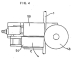
- a shaft of a bending die 48 is coaxially provided in the extended axial direction of the arm 33, and a groove 50 is formed in the outer periphery of the bending die 48 in accordance with the bending radius.
- a clamping die 54 is provided.
- the clamping die 54 is operated by a cylinder 52 to move toward the bending die 48 and hold the work 1 together with the bending die 48.
- the clamping die 54 is constructed to perform so-called compression bending by rotating around the bending die 48 while the work 1 is held with the bending die 48.
- a pressure die 56 is also provided adjacent to the clamping die 54 for receiving reaction at the time of bending.
- Fig. 5 shows that the bending mechanism 44 is set upright.
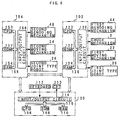
- the bending device 100 is operated and controlled by a controller or host computer 100, a first control device 102 and a second control device 104 to perform bending of the work 1.
- a logic circuit is mainly constituted of CPU 106, ROM 108 and RAM 110, and interconnected via a common bus 116 with an input/output circuit 114 for performing input/output with a keyboard 112 and a display 113.
- design data is entered into the host computer 100 via the keyboard 112 by an operator.
- Programs prepared for operating the first and second joint type robots 26, 28 are transmitted to the first and second control devices 102, 104 from the host computer 100, respectively.
- a logic circuit is mainly constituted of CPU 120, ROM 122 and RAM 124, and interconnected via a common bus 128 with an input/output circuit 126 for performing input/output with an outside servo motor, and the like.
- Signals are transmitted to the CPU 120 via the input/output circuit 126 from the first bending mechanism 44, the chuck mechanism 2, the first moving mechanism 22 and the first joint type robot 26.
- the CPU 120 Based on the data, signals and data in ROM 122 and RAM 124, the CPU 120 outputs drive signals for operating the first bending mechanism 44, the chuck mechanism 2, the first moving mechanism 22 and the first joint type robot 26 via the input/output circuit 126 to operate each mechanism.
- a logic circuit is mainly constituted of CPU 150, ROM 152 and RAM 154, and interconnected via a common bus 158 with an input/output circuit 156 for performing input/output with an outside servo motor, and the like.
- Signals are transmitted to the CPU 150 via the input/output circuit 156 from the second bending mechanism 46, the second moving mechanism 24 and the second joint type robot 28.
- the CPU 150 Based on the data, signals and data in ROM 152 and RAM 154, the CPU 150 outputs drive signals for operating the second bending mechanism 46, the second moving mechanism 24 and the second joint type robot 28 via the input/output circuit 156 to operate each mechanism.
- a dividing point A0 substantially in the center of the longitudinal work 1 is grasped by the chuck mechanism 2.
- operation is performed as preset.
- the joints 37 to 39 are rotated, the first bending mechanism 44 is inverted, and the bending die 48 is moved in such a manner that the inner surface of the groove 50 of the bending die 48 abuts on the outer surface of the work 1.
- the joints 37 to 39 are rotated to turn the groove 50 of the bending die 48 in the bending direction of the work 1.
- the clamping die 54 of the first bending mechanism 44 is moved, and the work 1 is held by the bending die 48 and the clamping die 54.
- the clamping die 54 is rotated around the bending die 48 by the predetermined angle as shown by an arrow C in Fig. 4, and the work 1 is bent.
- the clamping die 54 After the clamping die 54 is rotated only by the set angle to bend the work 1, the clamping die 54 and the pressure die 56 are moved to release the work 1. Additionally, the same operation is performed in the second bending mechanism 46 of the second joint type robot 28, and the work 1 is bent.
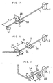
- the drive mechanism 14 is operated again. As shown in Fig. 9B, the moving base 10 is moved toward the chuck mechanism 2 until the next bending position is reached. After the moving base 10 is moved to the next bending position, the work 1 is bent by the first bending mechanism 44 as described above.
- the first joint type robot 26 is moved to the next bending position, the joints 37 to 39 are rotated, and the first bending mechanism 44 is set up vertical. Subsequently, the first bending mechanism 44 is operated to bend the work 1. In this manner, the work 1 held by the chuck mechanism 2 is successively bent from its end toward the chuck mechanism 2.
- the attitude of the first bending mechanism 44 needs to be changed from the inverted state to the upright state.
- the drive mechanism 14 is operated to move the moving base 10 from the bending position Q2 of Fig. 9B to the bending position Q3 of Fig. 9C, the joints 37 to 39 are rotated, and the attitude of the first bending mechanism 44 is changed as shown in Figs. 10A to 10C.
- the attitude of the first bending mechanism 44 is changed by rotating the joints 37 to 39 while the work 1 is remained between the bending die 48 and the clamping die 54.
- the attitude shown in Fig. 10A is changed to a state in which the first bending mechanism 44 is directed laterally as shown in Fig. 10B, and further changed to a state in which the first bending mechanism 44 is set upright.
- the joints 37 to 39 are rotated in such a manner that the work 1 is kept between the bending die 48 and the clamping die 54.
- the attitude change is controlled according to steps shown in the flowchart of Fig. 11. At step 400, the data of the center position of the work 1 is read.
- step 410 the clamping die 54 and the pressure die 56 are slightly moved away from the work 1.
- step 420 based on the obtained center position data, the attitude of the bending mechanism is changed by rotating the bending die 48, the clamping die 54 and the pressure die 56 around the center position.
- the first bending mechanism 44 is moved to the next bending position without being retracted from the work 1. Additionally, the attitude of the first bending mechanism 44 is changed in accordance with the next bending direction. Therefore, the tact time is shortened. The same applies to the second joint type robot 28.
- the bending of the work 1 is performed based on the design data of the work 1.
- the design data is given as the three-dimensional coordinate data of an orthogonal coordinate system.
- the design data is entered into the host computer 100 via the keyboard 112.
- the design data is the coordinate data of the center line of the work 1.
- the intersection of the centerlines of straight portions of the work 1 is regarded as the bending point, and XYZ coordinate of the bending point is used as the design data.
- the coordinate data of both ends of the work 1 is also entered as the design data.
- one end of the work 1 is a bending point Q0 (origin)
- the other end is a bending point Qe
- the design data of bending points Q1 to Q6 between Q0 and Qe is entered.
- step 200 it is first determined at step 200 whether or not the design data of a new work 1 is prepared. It is determined whether or not the work 1 is new in response to input from the keyboard 112. When the work 1 is new, the design data is read at step 210.
- the design data is converted to the working data constituted of a feeding pitch P between bending points Q, bending direction angle R and bending angle B at step 220.
- the working data is obtained, for example, when the work 1 is bent/worked successively from the bending point Q0 toward the other-end bending point Qe only by, the first joint type robot 26.
- the feeding pitch P indicates a feeding amount of the first joint type robot 26 determined by considering the bending radius (30 in Table 1) along the axial direction (Z-axis direction in Fig. 8) of the work 1 by the first moving mechanism 22.
- the bending direction angle R is an angle indicating the attitude of the first and second bending mechanisms 44, 46, while the bending angle B indicates an angle by which the work 1 is bent, i.e., a rotating angle of the clamping die 54 in the direction of the arrow C shown in Fig. 4.
- the values of the working data are calculated in an increment manner.
- the dividing point A0 is a point of the work 1 held by the chuck mechanism 2.
- the work 1 is bent/worked on opposite sides of the dividing point A0 by the first joint type robot 26 and the second joint type robot 28. As shown in Fig. 8, substantially the center of the straight portion of the work 1 having a length enough to be held by the chuck mechanism 2 is selected as the dividing point A0.
- the working data is distributed to the first and second joint type robots 26, 28 at the dividing point A0 as a reference at step 240.
- Table 2 the working of the bending points Q1 to Q3 between the one-end bending point Q0 and the dividing point A0 is allotted to the first joint type robot 26.
- step 250 it is determined at step 250 whether or not the data is to be corrected. It is determined in accordance with the input from the keyboard 112 whether or not the data is to be corrected.
- step 270 the process at and after step 270 is executed, so that the working data is transferred to the first and second control devices 102, 104 from the host computer 1,00. After the data is transferred, the control process is once completed, and the work 1 is bent/worked based on the transferred working data.
- the feeding pitch P, bending direction angle R and bending angle B of each of the bending points Q1 to Q6 are measured. Subsequently, when the shape of the bent work 1 is different from the working data, the feeding pitch P, bending direction angle R and the bending angle B in the working data shown in Table 2 or 3 are directly corrected by an operator.
- the working data preparation process when it is determined at the step 200 that the work 1 is not new and it is determined at the step 250 that the data is to be corrected, then the working data is corrected at step 260.
- Tables 2, 3 are indicated on the display 113, and the working data of Tables 2, 3 are corrected based on the input from the keyboard 112.
- the feeding pitch P of the bending point Q3 in the working data shown in table 2 is corrected.
- the correction amount is determined by measuring the pitch between the bending points Q2 and Q3 with a ruler or the like, and the feeding pitch P is increased/decreased. Even when the feeding pitch P is corrected, the feeding pitches P of the other bending points Q undergo no influence.
- each bending point Q can be corrected without influencing the data of the other bending points.
- the process of the steps 200 to 220 is executed by the working data preparing means, and the process of the steps 250 and 260 is executed by the correcting means.
- the process of the step 230 is executed by the dividing point determining means.
- a twist angle is set to zero degree
- a rotation angle of a clockwise direction is set to a positive angle
- a rotation angle of a counterclockwise direction is set to a negative angle.
- the twist angle indicates an angle of the first bending mechanism 44 when the work 1 is finally bent/worked by the first bending mechanism 44 of the first joint type robot 26.
- a first pattern processing is performed when the twist angle is in the range of -30 to 20 degrees
- a second pattern processing is performed when the twist angle is in the range of 20 to 120 degrees
- a third pattern processing is performed when the twist angle is in the range of 120 to 250 degrees
- a fourth pattern processing is performed when the twist angle is in the range of 250 to 272 degrees
- a fifth pattern processing is performed when the twist angle is in the range of - 30 to -90 degrees.
- Fig. 13 first, when the bending process is completed, it is determined at step 600 whether or not the work 1 is automatically unloaded. It is preset via the keyboard 112 whether or not the unloading is automatic. When it is determined that the work 1 is automatically unloaded, the twist angle of the first bending mechanism 44 of the first joint type robot 26 is determined at steps 610, 630, 650 and 670.
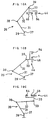
- Fig. 14A the first joint type robot 26 is shown by a solid line, while the second joint type robot 28 is shown by a two-dot chain line. Since Figs. 14B to 14E show only the first joint type robot 26, two-dot chain lines in these drawings also show the first joint type robot 26. In Figs. 14B to 14E, the movement of the first joint type robot 26 is shown by double-line arrows.
- the first pattern processing is performed at step 620.
- the work 1 in a position Po inside the groove is horizontally moved in a direction shown by an arrow by the second joint type robot 28 to substantially the middle position between the clamping die and the bending die.
- the work 1 is moved upward by the second joint type robot 28 and extracted from bending mechanism 44, the work 1 is moved toward unloading position Pa by the second joint type robot 28.
- the first joint type robot 26 does not move.
- the second pattern processing is performed at step 640.
- the first joint type robot 26 is moved downward as shown by a two-dot chain line in such a manner that the work 1 is positioned in the middle of the bending die and the clamping die of the first bending mechanism 44, while the work 1 is held by the second joint type robot 28.
- the work 1 is moved toward the unloading position Pa by the second joint type robot 28.
- the third pattern processing is executed at step 660.
- the first joint type robot 26 is moved toward the left as shown by the two-dot chain line in such a manner that the work 1 is positioned between the bending die and the clamping die of the first bending mechanism 44, while the work 1 is held by the second joint type robot 28. Thereafter, in order to disengage the work 1 from the first bending mechanism 44, the first joint type robot 26 is moved upward, and further rotated in the counterclockwise direction. The first joint type robot 26 is thus positioned not to interfere with the unloading path of the work 1. Subsequently, the work 1 is moved toward the unloading position Pa by the second joint type robot 28.
- the fourth pattern processing is executed at step 680.
- the first joint type robot 26 is moved upward as shown by the two-dot chain line in such a manner that the work 1 is positioned in the middle of the bending die and the clamping die of the first bending mechanism 44, while the work 1 is held by the second joint type robot 28. Thereafter, in order to disengage the work 1 from the first bending mechanism 44, the first joint type robot 26 is moved to the right, and further rotated in the counterclockwise direction. The first joint type robot 26 is thus positioned not to interfere with the- unloading path of the work 1. Subsequently, the work 1 is moved toward the unloading position Pa by the second joint type robot 28.
- the fifth pattern processing is executed at step 690.
- the first joint type robot 26 is moved upward to the right as shown by the two-dot chain line in such a manner that the work 1 is positioned in the middle of the bending die and the clamping die of the first bending mechanism 44, while the work 1 is held by the second joint type robot 28.
- the first joint type robot 26 is moved downward to the right. The first joint type robot 26 is thus positioned not to interfere with the unloading path of the work 1. Subsequently, the work 1 is moved toward the unloading position Pa by the second joint type robot 28.
- a processing by teaching is executed at step 700. Specifically, a path for moving the first bending mechanism 44 by the first joint type robot 26 and moving the work 1 to the unloading position Pa by the second joint type robot 28 is taught and stored.
- the first and second joint type robots 26 and 28 remove the work 1 from the groove of the first bending mechanism 44 and move it to the unloading position Pa according to the taught and stored moving path. Additionally, the process of the steps 610 to 690 is executed by the automatic delivery controlling means, while the process of the step 700 is executed by the teaching delivery controlling means.
- the moving pattern of the work 1 is determined in accordance with the twist angle of the first bending mechanism 44 in order to unload the work 1 by the second bending mechanism 46 without being interfered with by the first bending mechanism 44, but the first bending mechanism 44 and the second bending mechanism 46 may be operated in reverse. Specifically, while the work is held by one of the bending mechanisms, it is unloaded without interfering with the other bending mechanism.
- a bending device in which working data of feeding pitch between bending points, bending direction angle and bending angle is prepared from design data of a work, and a dividing point is determined to share the bending process by first and second joint type robots at one place of a straight line of the work able to be held by a chuck mechanism. After trial working, the working data is corrected.
- the first and second joint type robots having joints rotatable around axes parallel with the axial direction of the work are moved to the bending position.
- the work is held by a bending die and a clamping die rotatable around the bending die of a bending mechanism attached to the tip end of each joint type robot, and bent/worked by rotating the clamping die.
- each joint When moving to the next moving position, each joint is rotated to change the attitude of the bending mechanism, and the bending mechanism is moved along the work while the work remains between the bending die and the clamping die. After the bending process is completed, the work is held by the bending mechanism of the second joint type robot, moved in accordance with the angle of the bending mechanism of the first joint type robot in a direction in which the bending mechanism of the first joint type robot is not interfered with, and automatically moved to the unloading position.
Landscapes
- Engineering & Computer Science (AREA)
- Mechanical Engineering (AREA)
- Bending Of Plates, Rods, And Pipes (AREA)
Applications Claiming Priority (4)
| Application Number | Priority Date | Filing Date | Title |
|---|---|---|---|
| JP2219498A JPH11221625A (ja) | 1998-02-03 | 1998-02-03 | 関節型ロボットによる曲げ加工方法 |
| JP02219298A JP3912885B2 (ja) | 1998-02-03 | 1998-02-03 | 曲げ加工装置 |
| JP2219398A JPH11221624A (ja) | 1998-02-03 | 1998-02-03 | 曲げ加工装置 |
| EP99102085A EP0934783B1 (de) | 1998-02-03 | 1999-02-02 | Biegevorrichtung |
Related Parent Applications (1)
| Application Number | Title | Priority Date | Filing Date |
|---|---|---|---|
| EP99102085A Division EP0934783B1 (de) | 1998-02-03 | 1999-02-02 | Biegevorrichtung |
Publications (2)
| Publication Number | Publication Date |
|---|---|
| EP1690609A1 true EP1690609A1 (de) | 2006-08-16 |
| EP1690609B1 EP1690609B1 (de) | 2007-12-12 |
Family
ID=27283752
Family Applications (4)
| Application Number | Title | Priority Date | Filing Date |
|---|---|---|---|
| EP07107514A Expired - Lifetime EP1810763B1 (de) | 1998-02-03 | 1999-02-02 | Biegevorrichtung |
| EP99102085A Expired - Lifetime EP0934783B1 (de) | 1998-02-03 | 1999-02-02 | Biegevorrichtung |
| EP06113226A Expired - Lifetime EP1690609B1 (de) | 1998-02-03 | 1999-02-02 | Biegevorrichtung |
| EP06113225A Expired - Lifetime EP1688194B1 (de) | 1998-02-03 | 1999-02-02 | Biegevorrichtung |
Family Applications Before (2)
| Application Number | Title | Priority Date | Filing Date |
|---|---|---|---|
| EP07107514A Expired - Lifetime EP1810763B1 (de) | 1998-02-03 | 1999-02-02 | Biegevorrichtung |
| EP99102085A Expired - Lifetime EP0934783B1 (de) | 1998-02-03 | 1999-02-02 | Biegevorrichtung |
Family Applications After (1)
| Application Number | Title | Priority Date | Filing Date |
|---|---|---|---|
| EP06113225A Expired - Lifetime EP1688194B1 (de) | 1998-02-03 | 1999-02-02 | Biegevorrichtung |
Country Status (4)
| Country | Link |
|---|---|
| US (3) | US6185968B1 (de) |
| EP (4) | EP1810763B1 (de) |
| KR (1) | KR100550098B1 (de) |
| DE (4) | DE69931087T2 (de) |
Families Citing this family (28)
| Publication number | Priority date | Publication date | Assignee | Title |
|---|---|---|---|---|
| JP3663323B2 (ja) * | 1999-04-05 | 2005-06-22 | シャープ株式会社 | ミリ波送信装置およびミリ波受信装置 |
| NO20004059D0 (no) * | 2000-08-11 | 2000-08-11 | Norsk Hydro As | Anordning og fremgangsmÕte ved fremstilling av langstrakte metallgjenstander |
| ITVI20010031A1 (it) * | 2001-02-05 | 2002-08-05 | S I L Met Spa | Macchina per la curvatura a freddo mediante stiramento controllato diprofili allungati |
| US6612143B1 (en) | 2001-04-13 | 2003-09-02 | Orametrix, Inc. | Robot and method for bending orthodontic archwires and other medical devices |
| US20060240125A1 (en) * | 2005-04-21 | 2006-10-26 | Astrup Arne V | Composition for affecting weight loss |
| EP1350577A1 (de) | 2002-04-03 | 2003-10-08 | Trumpf Pulzer GmbH + Co. KG | Biegemaschine zum Biegen von stangen- und/oder von stabartigen Werkstücken, insbesondere von Rohren |
| EP1350578B1 (de) * | 2002-04-03 | 2007-04-25 | Trumpf Werkzeugmaschinen GmbH + Co. KG | Biegemaschine zum Biegen von stangen- und/oder von stabartigen Werkstücken, insbesondere von Rohren |
| US7152983B2 (en) * | 2003-03-06 | 2006-12-26 | 3M Innovative Properties Company | Lamina comprising cube corner elements and retroreflective sheeting |
| FR2859653B1 (fr) * | 2003-09-12 | 2006-03-17 | Silfax Sa | Machine orbitale pour le cintrage des tubes |
| DE602005003524T2 (de) * | 2004-09-27 | 2008-10-23 | Kabushiki Kaisha Opton | Biegevorrichtung |
| EP1810762B1 (de) * | 2004-11-01 | 2012-09-26 | Kabushiki Kaisha Opton | Biegevorrichtung |
| EP1849536B1 (de) * | 2006-04-07 | 2008-05-28 | WAFIOS Aktiengesellschaft | Biegemaschine für stabförmige Werkstücke aus Draht, Rohrmaterial oder dgl. |
| DE502007005038D1 (de) | 2007-02-07 | 2010-10-28 | Wafios Ag | Biegemaschine |
| ES2322624T3 (es) | 2007-03-14 | 2009-06-23 | Wafios Aktiengesellschaft | Enganchador para la empuñadura y la sujecion de piezas de trabajo alargadas, en particular, en maquinas dobladoras. |
| ATE443597T1 (de) | 2007-06-29 | 2009-10-15 | Wafios Ag | Linearführung |
| EP2177287B1 (de) | 2008-10-17 | 2011-11-30 | WAFIOS Aktiengesellschaft | Stützbackenanordnung zum gleitenden seitlichen Abstützen von stab- und rohrförmigen Werkstücken an Biegemaschinen |
| JP5330064B2 (ja) * | 2009-04-08 | 2013-10-30 | 株式会社オプトン | 曲げ加工装置 |
| JP5405879B2 (ja) * | 2009-04-08 | 2014-02-05 | 株式会社オプトン | 曲げ加工装置 |
| JP5405878B2 (ja) * | 2009-04-08 | 2014-02-05 | 株式会社オプトン | 曲げ加工装置 |
| JP6619560B2 (ja) | 2015-04-15 | 2019-12-11 | 株式会社オプトン | 曲げ加工装置 |
| ITUA20164225A1 (it) * | 2016-06-09 | 2017-12-09 | Tecnofer Srl | Metodo e apparato per la realizzazione di una spira per coclea |
| CN108994165B (zh) * | 2018-08-24 | 2020-05-12 | 白尊敏 | 前后多工位管端一体组合弯管机 |
| CN111822561B (zh) * | 2019-05-14 | 2022-02-11 | 哈尔滨工业大学 | 一种型材或棒材无模热弯曲成形随动弯转装置及使用方法 |
| CN110560529A (zh) * | 2019-09-10 | 2019-12-13 | 广东职业技术学院 | 一种应用极坐标法的弯管加工方法及系统 |
| TWI722824B (zh) * | 2020-03-10 | 2021-03-21 | 陳鈺蓁 | 鋼筋彎曲機 |
| EP4180144A1 (de) * | 2021-11-16 | 2023-05-17 | Itronics S.r.l. | Vorrichtung und verfahren zum biegen mit strecken von metallischen elementen |
| DE102023106773A1 (de) * | 2023-03-17 | 2024-09-19 | Universität Siegen Rechtsfähige Körperschaft des öffentlichen Rechts | Biegevorrichtung und Verfahren zum Biegen eines Profils |
| US20250326613A1 (en) * | 2024-04-20 | 2025-10-23 | Joseph Homsy | Robotic Arms on a scissor lift with conduit bending apparatus and material for installation |
Citations (5)
| Publication number | Priority date | Publication date | Assignee | Title |
|---|---|---|---|---|
| DE3620151A1 (de) * | 1985-06-19 | 1987-02-26 | Asea Ab | Verfahren und robotereinrichtung zum biegen von stangenfoermigen materialien oder werkstuecken |
| DE3900990A1 (de) * | 1989-01-12 | 1990-08-02 | Bundy Gmbh | Verfahren zum rechnergestuetzten auslegen des verlaufs, zum herstellen und einrichtung zum herstellen von raeumlich winklig gebogenen, kleinkalibrigen rohrleitungen, insbes. von kraftstoff- oder bremsleitungen im kraftfahrzeugbau |
| US4945747A (en) * | 1989-05-11 | 1990-08-07 | Chuo Electric Manufacturing Co., Ltd. | Apparatus for bending elongated materials in any direction |
| WO1991013706A1 (en) * | 1990-03-07 | 1991-09-19 | Johannes Tokola | Method for bending pipes |
| EP0789289A2 (de) * | 1996-02-09 | 1997-08-13 | Faro Technologies Inc. | Verfahren zum Entwerfen oder Fertigen gebogener Röhren |
Family Cites Families (19)
| Publication number | Priority date | Publication date | Assignee | Title |
|---|---|---|---|---|
| DE8309569U1 (de) * | 1983-03-31 | 1985-02-21 | Lang, Thomas Peter, Dipl.-Wirtsch.-Ing., 6120 Michelstadt | Maschine zum biegen von strangmaterial |
| JPS59189415A (ja) * | 1983-04-13 | 1984-10-27 | Hitachi Ltd | 工業用ロボツトの動作教示方法および装置 |
| US4662204A (en) * | 1985-01-17 | 1987-05-05 | Usui Kokusai Sangyo Kabushiki Kaisha | Apparatus for automatically bending metallic tubes |
| KR900008539B1 (ko) * | 1985-05-30 | 1990-11-24 | 마쯔시다덴기산교 가부시기가이샤 | 로보트의 연속경로 제어방법 |
| JPH089063B2 (ja) * | 1985-10-21 | 1996-01-31 | 臼井国際産業株式会社 | パイプ自動ベンダーにおける曲げ加工ユニット装置 |
| JPS62267021A (ja) * | 1986-05-15 | 1987-11-19 | Chuo Electric Mfg Co Ltd | 曲げ加工装置 |
| JPH0299724A (ja) * | 1988-10-04 | 1990-04-11 | Mazda Motor Corp | V型エンジンのノックセンサ取付構造 |
| JP2522359B2 (ja) * | 1988-10-06 | 1996-08-07 | トヨタ自動車株式会社 | 二段タ―ボエンジンの過給制御装置 |
| US5642291A (en) * | 1989-12-22 | 1997-06-24 | Amada Company, Limited Of Japan | System for creating command and control signals for a complete operating cycle of a robot manipulator device of a sheet metal bending installation by simulating the operating environment |
| JPH0830978B2 (ja) * | 1990-05-22 | 1996-03-27 | 株式会社神戸製鋼所 | 産業用ロボットの教示・再生方法 |
| JPH0513011A (ja) | 1991-07-05 | 1993-01-22 | Nec Corp | 進行波管用結合空胴形遅波回路 |
| JP2895672B2 (ja) * | 1992-01-28 | 1999-05-24 | ファナック株式会社 | 複数ロボット制御方法 |
| JPH0565440U (ja) * | 1992-02-03 | 1993-08-31 | 安川商事株式会社 | ワイヤベンディング装置 |
| DE4242002A1 (de) * | 1992-12-12 | 1994-06-16 | Herbert Hirschmiller | Vorrichtung und Verfahren zum Biegen von Strangmaterial |
| JPH07306705A (ja) * | 1994-05-11 | 1995-11-21 | Amada Metrecs Co Ltd | 曲げ加工機におけるロボットの教示装置 |
| US5835684A (en) * | 1994-11-09 | 1998-11-10 | Amada Company, Ltd. | Method for planning/controlling robot motion |
| US5627132A (en) * | 1995-11-07 | 1997-05-06 | Voyager Enterprises Inc. | Method and composition for plant preservation without leaf curling |
| JP3716949B2 (ja) * | 1996-05-17 | 2005-11-16 | 臼井国際産業株式会社 | 多連式パイプ曲げ加工装置 |
| US5927132A (en) * | 1998-04-30 | 1999-07-27 | Schnell Spa | Method of bending bars |
-
1999
- 1999-02-02 DE DE69931087T patent/DE69931087T2/de not_active Expired - Lifetime
- 1999-02-02 EP EP07107514A patent/EP1810763B1/de not_active Expired - Lifetime
- 1999-02-02 DE DE69937763T patent/DE69937763T2/de not_active Expired - Lifetime
- 1999-02-02 US US09/241,711 patent/US6185968B1/en not_active Expired - Lifetime
- 1999-02-02 EP EP99102085A patent/EP0934783B1/de not_active Expired - Lifetime
- 1999-02-02 DE DE69939499T patent/DE69939499D1/de not_active Expired - Lifetime
- 1999-02-02 DE DE69940752T patent/DE69940752D1/de not_active Expired - Lifetime
- 1999-02-02 EP EP06113226A patent/EP1690609B1/de not_active Expired - Lifetime
- 1999-02-02 EP EP06113225A patent/EP1688194B1/de not_active Expired - Lifetime
- 1999-02-03 KR KR1019990003532A patent/KR100550098B1/ko not_active Expired - Fee Related
-
2000
- 2000-02-01 US US09/495,849 patent/US6237380B1/en not_active Expired - Lifetime
- 2000-02-01 US US09/495,848 patent/US6189353B1/en not_active Expired - Lifetime
Patent Citations (5)
| Publication number | Priority date | Publication date | Assignee | Title |
|---|---|---|---|---|
| DE3620151A1 (de) * | 1985-06-19 | 1987-02-26 | Asea Ab | Verfahren und robotereinrichtung zum biegen von stangenfoermigen materialien oder werkstuecken |
| DE3900990A1 (de) * | 1989-01-12 | 1990-08-02 | Bundy Gmbh | Verfahren zum rechnergestuetzten auslegen des verlaufs, zum herstellen und einrichtung zum herstellen von raeumlich winklig gebogenen, kleinkalibrigen rohrleitungen, insbes. von kraftstoff- oder bremsleitungen im kraftfahrzeugbau |
| US4945747A (en) * | 1989-05-11 | 1990-08-07 | Chuo Electric Manufacturing Co., Ltd. | Apparatus for bending elongated materials in any direction |
| WO1991013706A1 (en) * | 1990-03-07 | 1991-09-19 | Johannes Tokola | Method for bending pipes |
| EP0789289A2 (de) * | 1996-02-09 | 1997-08-13 | Faro Technologies Inc. | Verfahren zum Entwerfen oder Fertigen gebogener Röhren |
Non-Patent Citations (1)
| Title |
|---|
| MACHINE DESIGN, PENTON MEDIA, CLEVELAND, OH, US, vol. 1, no. 49, January 1977 (1977-01-01), pages 42, XP002075440, ISSN: 0024-9114 * |
Also Published As
| Publication number | Publication date |
|---|---|
| EP1688194B1 (de) | 2008-09-03 |
| KR100550098B1 (ko) | 2006-02-08 |
| EP1688194A3 (de) | 2006-11-02 |
| EP0934783A2 (de) | 1999-08-11 |
| EP0934783B1 (de) | 2006-05-03 |
| US6185968B1 (en) | 2001-02-13 |
| US6189353B1 (en) | 2001-02-20 |
| DE69939499D1 (de) | 2008-10-16 |
| DE69931087T2 (de) | 2006-09-21 |
| DE69940752D1 (de) | 2009-05-28 |
| EP1688194A2 (de) | 2006-08-09 |
| US6237380B1 (en) | 2001-05-29 |
| DE69931087D1 (de) | 2006-06-08 |
| EP1690609B1 (de) | 2007-12-12 |
| DE69937763T2 (de) | 2008-11-27 |
| KR19990045872A (ko) | 1999-06-25 |
| EP1810763A1 (de) | 2007-07-25 |
| DE69937763D1 (de) | 2008-01-24 |
| EP1810763B1 (de) | 2009-04-15 |
| EP0934783A3 (de) | 2001-06-20 |
Similar Documents
| Publication | Publication Date | Title |
|---|---|---|
| EP1690609B1 (de) | Biegevorrichtung | |
| US7905699B2 (en) | Transfer robot, transfer method, and control method | |
| US20210187745A1 (en) | Automated calibration system and method for a workpiece coordinate frame of a robot | |
| US5993140A (en) | Apparatus for loading pipes onto processing machines | |
| EP0554533B1 (de) | Drahtbiegevorrichtung | |
| EP1488893A2 (de) | Greifvorrichtung für Verbindungen, Inspektionssystem mit einer solchen Greifvorrichtung und Verbindunssystem | |
| EP3542973B1 (de) | Arbeitsroboter und verfahren zur arbeitspositionskorrektur | |
| WO2016167301A1 (ja) | 曲げ加工装置 | |
| JP2019048349A (ja) | ロボットシステム、ロボット制御装置および被加工物の製造方法 | |
| EP1810762B1 (de) | Biegevorrichtung | |
| KR940003948B1 (ko) | 산업용 로봇의 제어방법 및 장치 | |
| EP1886771B1 (de) | Verfahren zur berechnung eines rotationsmittelpunktes, verfahren zur berechnung einer rotationsachse, verfahren zur erstellung eines programms, betriebsverfahren und robotergerät | |
| KR20000018642A (ko) | 스카라 로봇용 좌표계 편차 조정 장치 및 이에 적합한 방법 | |
| KR101296537B1 (ko) | 자동화 로봇용 클램핑 기구 | |
| JP3202731B2 (ja) | 搬送装置 | |
| JP2562353B2 (ja) | ロボットの位置決め方法 | |
| JPS62148173A (ja) | 関節型ロボツトの原点調整方法 | |
| JPH01159188A (ja) | 産業用ロボットの制御方法 | |
| JPH0440128B2 (de) | ||
| EP1230996A2 (de) | Kaltbiegemaschine, wirkend durch gesteuertes Ziehen von länglichen Profilen | |
| JP2025037315A (ja) | 基板搬送用ロボット | |
| JPS61249223A (ja) | 加工機における工具の姿勢制御方法 | |
| KR20260062327A (ko) | 로봇 벤딩 자동화 시스템 | |
| JP2026057198A (ja) | マニピュレータの位置調整方法 | |
| JPH04174005A (ja) | ロボットコントーラ |
Legal Events
| Date | Code | Title | Description |
|---|---|---|---|
| PUAI | Public reference made under article 153(3) epc to a published international application that has entered the european phase |
Free format text: ORIGINAL CODE: 0009012 |
|
| AC | Divisional application: reference to earlier application |
Ref document number: 0934783 Country of ref document: EP Kind code of ref document: P |
|
| AK | Designated contracting states |
Kind code of ref document: A1 Designated state(s): DE FR GB IT |
|
| 17P | Request for examination filed |
Effective date: 20061127 |
|
| AKX | Designation fees paid |
Designated state(s): DE FR GB IT |
|
| GRAP | Despatch of communication of intention to grant a patent |
Free format text: ORIGINAL CODE: EPIDOSNIGR1 |
|
| GRAS | Grant fee paid |
Free format text: ORIGINAL CODE: EPIDOSNIGR3 |
|
| GRAA | (expected) grant |
Free format text: ORIGINAL CODE: 0009210 |
|
| AC | Divisional application: reference to earlier application |
Ref document number: 0934783 Country of ref document: EP Kind code of ref document: P |
|
| AK | Designated contracting states |
Kind code of ref document: B1 Designated state(s): DE FR GB IT |
|
| REG | Reference to a national code |
Ref country code: GB Ref legal event code: FG4D |
|
| REF | Corresponds to: |
Ref document number: 69937763 Country of ref document: DE Date of ref document: 20080124 Kind code of ref document: P |
|
| ET | Fr: translation filed | ||
| PLBE | No opposition filed within time limit |
Free format text: ORIGINAL CODE: 0009261 |
|
| STAA | Information on the status of an ep patent application or granted ep patent |
Free format text: STATUS: NO OPPOSITION FILED WITHIN TIME LIMIT |
|
| 26N | No opposition filed |
Effective date: 20080915 |
|
| PGFP | Annual fee paid to national office [announced via postgrant information from national office to epo] |
Ref country code: FR Payment date: 20120228 Year of fee payment: 14 |
|
| PGFP | Annual fee paid to national office [announced via postgrant information from national office to epo] |
Ref country code: IT Payment date: 20120224 Year of fee payment: 14 Ref country code: GB Payment date: 20120222 Year of fee payment: 14 |
|
| PGFP | Annual fee paid to national office [announced via postgrant information from national office to epo] |
Ref country code: DE Payment date: 20130227 Year of fee payment: 15 |
|
| GBPC | Gb: european patent ceased through non-payment of renewal fee |
Effective date: 20130202 |
|
| REG | Reference to a national code |
Ref country code: FR Ref legal event code: ST Effective date: 20131031 |
|
| PG25 | Lapsed in a contracting state [announced via postgrant information from national office to epo] |
Ref country code: FR Free format text: LAPSE BECAUSE OF NON-PAYMENT OF DUE FEES Effective date: 20130228 Ref country code: GB Free format text: LAPSE BECAUSE OF NON-PAYMENT OF DUE FEES Effective date: 20130202 |
|
| REG | Reference to a national code |
Ref country code: DE Ref legal event code: R119 Ref document number: 69937763 Country of ref document: DE |
|
| REG | Reference to a national code |
Ref country code: DE Ref legal event code: R119 Ref document number: 69937763 Country of ref document: DE Effective date: 20140902 |
|
| PG25 | Lapsed in a contracting state [announced via postgrant information from national office to epo] |
Ref country code: DE Free format text: LAPSE BECAUSE OF NON-PAYMENT OF DUE FEES Effective date: 20140902 |
|
| PG25 | Lapsed in a contracting state [announced via postgrant information from national office to epo] |
Ref country code: IT Free format text: LAPSE BECAUSE OF NON-PAYMENT OF DUE FEES Effective date: 20140202 |