EP1691027A2 - Rolladenkasten sowie Vorrichtung und Verfahren zu dessen Herstellung - Google Patents
Rolladenkasten sowie Vorrichtung und Verfahren zu dessen Herstellung Download PDFInfo
- Publication number
- EP1691027A2 EP1691027A2 EP06002829A EP06002829A EP1691027A2 EP 1691027 A2 EP1691027 A2 EP 1691027A2 EP 06002829 A EP06002829 A EP 06002829A EP 06002829 A EP06002829 A EP 06002829A EP 1691027 A2 EP1691027 A2 EP 1691027A2
- Authority
- EP
- European Patent Office
- Prior art keywords
- roller shutter
- boring
- shutter box
- drilling
- concrete block
- Prior art date
- Legal status (The legal status is an assumption and is not a legal conclusion. Google has not performed a legal analysis and makes no representation as to the accuracy of the status listed.)
- Granted
Links
- 238000004519 manufacturing process Methods 0.000 title claims abstract description 9
- 238000005553 drilling Methods 0.000 claims abstract description 29
- 239000000463 material Substances 0.000 claims abstract description 8
- 238000000034 method Methods 0.000 claims abstract 5
- 238000005096 rolling process Methods 0.000 claims description 17
- 239000011810 insulating material Substances 0.000 claims description 3
- 238000009434 installation Methods 0.000 abstract 1
- 239000003129 oil well Substances 0.000 abstract 1
- 239000006260 foam Substances 0.000 description 7
- 238000009413 insulation Methods 0.000 description 5
- 239000002245 particle Substances 0.000 description 5
- 239000002984 plastic foam Substances 0.000 description 4
- 229910000831 Steel Inorganic materials 0.000 description 2
- 230000006378 damage Effects 0.000 description 2
- 238000000465 moulding Methods 0.000 description 2
- 239000007787 solid Substances 0.000 description 2
- 239000010959 steel Substances 0.000 description 2
- 239000004566 building material Substances 0.000 description 1
- 238000013461 design Methods 0.000 description 1
- 238000005338 heat storage Methods 0.000 description 1
- 238000010438 heat treatment Methods 0.000 description 1
- 238000007654 immersion Methods 0.000 description 1
- 238000012423 maintenance Methods 0.000 description 1
- 239000002184 metal Substances 0.000 description 1
- 238000004806 packaging method and process Methods 0.000 description 1
- 239000004033 plastic Substances 0.000 description 1
- 229920006327 polystyrene foam Polymers 0.000 description 1
- 239000011148 porous material Substances 0.000 description 1
- 238000012545 processing Methods 0.000 description 1
- 238000013519 translation Methods 0.000 description 1
- 239000002023 wood Substances 0.000 description 1
Images
Classifications
-
- B—PERFORMING OPERATIONS; TRANSPORTING
- B23—MACHINE TOOLS; METAL-WORKING NOT OTHERWISE PROVIDED FOR
- B23B—TURNING; BORING
- B23B41/00—Boring or drilling machines or devices specially adapted for particular work; Accessories specially adapted therefor
- B23B41/02—Boring or drilling machines or devices specially adapted for particular work; Accessories specially adapted therefor for boring deep holes; Trepanning, e.g. of gun or rifle barrels
-
- B—PERFORMING OPERATIONS; TRANSPORTING
- B28—WORKING CEMENT, CLAY, OR STONE
- B28D—WORKING STONE OR STONE-LIKE MATERIALS
- B28D1/00—Working stone or stone-like materials, e.g. brick, concrete or glass, not provided for elsewhere; Machines, devices, tools therefor
- B28D1/14—Working stone or stone-like materials, e.g. brick, concrete or glass, not provided for elsewhere; Machines, devices, tools therefor by boring or drilling
-
- E—FIXED CONSTRUCTIONS
- E06—DOORS, WINDOWS, SHUTTERS, OR ROLLER BLINDS IN GENERAL; LADDERS
- E06B—FIXED OR MOVABLE CLOSURES FOR OPENINGS IN BUILDINGS, VEHICLES, FENCES OR LIKE ENCLOSURES IN GENERAL, e.g. DOORS, WINDOWS, BLINDS, GATES
- E06B9/00—Screening or protective devices for wall or similar openings, with or without operating or securing mechanisms; Closures of similar construction
- E06B9/02—Shutters, movable grilles, or other safety closing devices, e.g. against burglary
- E06B9/08—Roll-type closures
- E06B9/11—Roller shutters
- E06B9/17—Parts or details of roller shutters, e.g. suspension devices, shutter boxes, wicket doors, ventilation openings
- E06B9/17007—Shutter boxes; Details or component parts thereof
Definitions
- the invention relates to a roller shutter box, wherein the roller shutter box consists of a reinforced, solid block of aerated concrete and the rolling room for the up and unwindable on a shaft roller shutter drilled using a specially designed rig from the side walls of the porous concrete block by concentric and sideways drilling activity becomes.
- the invention further relates to an apparatus and a method for producing a roller shutter box and in particular with regard to the application of the rolling space.
- Blinds serve primarily to secure windows, but also to secure doors and gates.
- the blinds below the corresponding window, door or gate lintel on a shell shaft are wound up and unwound.
- the shaft is surrounded by the roller shutter of a box, the so-called roller shutter box, which is walled under the respective camber.
- the roller shutter box has several functions. He should form a panel and a seal. To meet these requirements, the roller shutter box usually has a U-shaped cross-section.
- roller shutter box In most cases, the roller shutter box must also carry a holder for the shaft and the roller shutter.
- various devices are known. The most commonly used drive is a hand-pulled band that acts on a disc. The disc sits on a shaft and has about the maximum diameter of the coil. With it finds a translation of the driving forces instead. But there are also known motor drives.
- the shaft, the roller shutter or the shutter and the actuator for the shaft are subject to wear. Maintenance is inevitable. Therefore, the roller shutter box must remain accessible.
- Typical moldings of particle foam are sheets of polystyrene foam and packaging foam.
- the invention has for its object to produce a roller shutter box made of aerated concrete, which is self-supporting, which avoids the above-mentioned disadvantages and also corresponds to the requirements of thermal insulation.
- the roller shutter box consists of a reinforced porous concrete block as an outer box section, wherein the rolling room is drilled with the aid of a special drilling rig centric sideways.
- the drilling rig provides two boring devices each mounted in a bearing tube and located on an axis opposite one another. Due to this configuration, the roller shutter box is very easy to produce in terms of production, as can be dispensed with elaborate mandrels to form the rolling room, as is the case, for example, in the disclosed in DE 297 06 935 U1 roller blind box.
- roller shutter box Preferred embodiments of the roller shutter box are specified in the subclaims 2 to 6.
- Claim 7 indicates a drilling device for the rolling room of the roller shutter box, according to which in each case a drilling device is mounted in two opposite each other on an axis bearing tubes.
- the roller shutter box can be created by a pendulum movement of the porous concrete block while avoiding a too large immersion depth of the drilling device.
- Preferred embodiments of this drilling device are specified in claims 8 and 9.
- the claims 10 to 13 relate to a method for producing a roller shutter box, which provides in its most general form that the rolling space of a reinforced aerated concrete block using a special drilling rig, wherein by means of two mounted in a bearing tube, on an axis opposite each other Drilling devices is bored centered sideways.
- the roller shutter box comprises an outer box element (1), which is self-supporting and a kind of inner box section (2), which can be additionally configured with heat-insulating material.
- the roller shutter box according to the invention for the wall thicknesses between 20 cm and 60 cm is made, each with a preferred height between 20 and 40 cm, a wall thickness between 2 and 5 cm and in lengths of up to 300 cm.
- the material used is an armored aerated concrete block (3).
- the shutter box is made of a single porous concrete block (3).
- the aerated concrete blocks can only be processed by means of the special drilling rig shown in FIG.
- This drilling rig consists of two stationary drills (4) and (5) with identical drilling tools, the drilling tools are aligned centrally on a common axis and the drill shaft (6) in a stable tube, the so-called bearing tube (7) is stored , In the two opposite each other on an axis bearing tubes (7) each have a drilling device (6) is mounted.
- the bearing tubes (7) are equipped with a suction device and are located on its axis at a distance of more than 2500 mm.
- the aerated concrete block (3) to be machined is placed on a tool table (9) located between the drills and fixed in the Y-axis and Z-axis, the X-axis representing the drilling axis.
- the table (9) is on rail members (8) in both X-axis directions to the drilling tools mobile.
- the upper part of the tool table (9) is moved in the Z-axis.
- the required rolling space (R) is drilled by means of the drills described (4, 5) by concentric and sideways drilling activity. The boring operations leading to the boring of the rolling room take place both simultaneously and not simultaneously.
- the opening (10) on the lower side of the shutter box is cut out by means of a special processing tool.
- the roller shutter box is then equipped with the for the inner box profile (2) certain additional insulation, as well as the lateral end faces with the bearing holders and the Gurtauslass.
- the roller shutter box according to the invention has the advantage of a very high thermal insulation due to the material used.
- Hardly any other solid wall building material has comparable heat conductivity as aerated concrete.
- the low thermal conductivity is caused by a large number of small air pores in the aerated concrete.
- the DIN 4108 contains requirements for thermal insulation and heat storage as well as thermal protection information for planning and execution in building physics. Aerated concrete consistently has a lower thermal conductivity than the standard DIN 4108 Part 4 calls.
- an additional thermal insulation can be installed by means of cut in shape foams such as Styrodur or similar insulating materials in different thicknesses.
Landscapes
- Engineering & Computer Science (AREA)
- Mechanical Engineering (AREA)
- Structural Engineering (AREA)
- Architecture (AREA)
- Civil Engineering (AREA)
- Mining & Mineral Resources (AREA)
- Excavating Of Shafts Or Tunnels (AREA)
- Building Environments (AREA)
Abstract
Description
- Die Erfindung bezieht sich auf einen Rolladenkasten, wobei der Rolladenkasten aus einem armierten, massiven Porenbetonklotz besteht und der Rollraum für den auf einer Welle auf- und abwickelbaren Rolladenpanzer mit Hilfe einer speziell konzipierten Bohranlage von den Seitenwänden des Porenbetonklotzes aus durch zentrisch und seitwärts angesetzte Bohrtätigkeit ausgebohrt wird. Die Erfindung bezieht sich ferner auf eine Vorrichtung sowie ein Verfahren zur Herstellung eines Rolladenkastens und insbesondere im Hinblick auf das Anlegen des Rollraums.
- Rolläden dienen vorrangig der Sicherung von Fenstern, aber auch der Sicherung von Türen und Toren. Dabei werden die Rolläden unterhalb des entsprechenden Fenster-, Tür- oder Torsturzes auf einer Panzerwelle auf-und abgewickelt.
- Üblicherweise wird die Welle mit dem Rolladenwickel von einem Kasten umgeben, dem so genannten Rolladenkasten, welcher unter dem jeweiligen Sturz eingemauert wird. Dabei hat der Rolladenkasten mehrere Funktionen. Er soll eine Verkleidung und eine Abdichtung bilden. Zur Erfüllung dieser Vorgaben hat der Rolladenkasten üblicherweise einen U-förmigen Querschnitt.
- Zumeist muss der Rolladenkasten auch eine Halterung für die Welle und den Rolladenwickel tragen. Zum Antrieb der Welle sind verschiedene Einrichtungen bekannt. Der häufigst verwendete Antrieb ist ein von Hand gezogenes Band, das auf eine Scheibe wirkt. Die Scheibe sitzt auf einer Welle und hat etwa den maximalen Durchmesser des Wickels. Damit findet eine Übersetzung der Antriebskräfte statt. Es sind aber auch Motorantriebe bekannt.
- Wie alle mechanischen Teile unterliegen die Welle, der Rolladenwickel bzw. die Rollade und die Betätigungseinrichtung für die Welle einem Verschleiß. Wartungen sind unvermeidlich. Deshalb muss der Rolladenkasten zugänglich bleiben.
- Seit einiger Zeit bestehen vielerlei Bemühungen, Rolladenkästen aus unterschiedlichen Materialien herzustellen, insbesondere aus Kunststoffschaum. Bislang hat sich nur eine Herstellung aus Partikelschaum durchsetzen können, wobei der Partikelschaum aus kleinen Schaumpartikeln besteht, die in einer Form erhitzt werden, sodass sie expandieren und an den durch die Erhitzung plastifizierten Berührungsflächen miteinander verschweißen.
- Alle Formkörper haben gemeinsam, dass ihre Festigkeit gering ist. Typische Formkörper aus Partikelschaum sind Platten aus Polystyrol-Hartschaumstoff und Verpackungsschaum.
- Zur Erhöhung der Festigkeit ist es bekannt, in den Formen Stahldrähte bzw. Betonstahlmatten einzulegen. Die Stahldrähte sind in verschiedener Hinsicht für die Konstruktion problematisch: Sie müssen in die Form eingelegt werden. Das bedingt einen erheblichen Vorrichtungs- und Arbeitsaufwand. Die Drähte verhalten sich wie Fremdkörper im Kunststoffschaum. Eine Belastung der Drähte verursacht die Gefahr einer Schädigung des Kunststoffschaumes, indem der Draht aufgrund der wirksamen Kräfte wie ein Messer durch den Kunststoffschaum fährt, was zwangsläufig zu einer Zerstörung führt.
- Neben dieser Herstellungsart auf der Basis von Partikelschaum bestehen weiterhin die traditionellen Herstellungsweisen, wobei die Wandungen des Rolladenkastens aus brettartigen Teilen aus Metall, Holz oder mehrkammerigen Kunststoffhohlprofilen bestehen. Bei diesen herkömmlichen Rolladenkästen besteht der Nachteil, dass verhältnismäßig viele einzelne Querschnittsteile, insbesondere für einen weitgehend geschlossenen Kastenquerschnitt, erforderlich sind.
- Zudem weisen die marktüblichen Rolladenkästen aufgrund der verwendeten Materialien oftmals eine zu hohe Wärmeleitfähigkeit auf und werfen hinsichtlich einer späteren Entsorgung Probleme auf.
- Der Erfindung liegt die Aufgabe zugrunde, einen Rolladenkasten aus Porenbeton herzustellen, der selbsttragend ausgebildet ist, der die oben angeführten Nachteile vermeidet und der darüber hinaus den Erfordernissen der Wärmedämmung entspricht.
- Ein Rolladenkasten entsprechend dem Patentanspruch 1 löst diese Aufgabe. Demnach besteht der Rolladenkasten aus einem armierten Porenbetonklotz als äußerem Kastenprofil, wobei der Rollraum mit Hilfe einer speziellen Bohranlage zentrisch seitwärts ausgebohrt wird. Die Bohranlage sieht zwei jeweils in einem Lagerrohr gelagerte, auf einer Achse einander gegenüberliegende Bohrvorrichtungen vor. Aufgrund dieser Ausgestaltung ist der Rolladenkasten produktionstechnisch sehr einfach herstellbar, da auf aufwändige Formkerne zur Ausbildung des Rollraums, wie dies beispielsweise bei dem in der DE 297 06 935 U1 offenbarte Rollokasten der Fall ist, verzichtet werden kann.
- Bevorzugte Ausführungsformen des Rolladenkastens sind in den Unteransprüchen 2 bis 6 angegeben.
- Anspruch 7 kennzeichnet eine Bohrvorrichtung für den Rollraum des Rolladenkastens, wonach in zwei einander auf einer Achse gegenüberliegenden Lagerrohren jeweils eine Bohrvorrichtung gelagert ist. Damit kann der Rolladenkasten durch eine pendelnde Bewegung des Porenbetonklotzes unter Vermeidung einer zu großen Eintauchtiefe der Bohrvorrichtung angelegt werden. Bevorzugte Ausbildungen dieser Bohrvorrichtung sind in den Ansprüchen 8 und 9 angegeben.
- Schließlich beziehen sich die Ansprüche 10 bis 13 auf ein Verfahren zur Herstellung eines Rolladenkastens, das in seiner allgemeinsten Ausprägung vorsieht, dass der Rollraum aus einem armierten Porenbetonklotz mit Hilfe einer speziellen Bohranlage entsteht, wobei mittels zweier in einem Lagerrohr gelagerter, auf einer Achse einander gegenüberliegender Bohrvorrichtungen zentrisch seitwärts ausgebohrt wird.
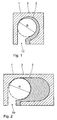
- Unter Bezugnahme auf die Figuren 1 bis 3 soll nachfolgend ein erfindungsgemäßer Rolladenkasten beschrieben werden. Es zeigen
- Fig. 1
- einen erfindungsgemäßen Rolladenkasten für eine geringe Mauerdicke,
- Fig. 2
- einen erfindungsgemäßen Rolladenkasten für eine stärkere Mauerdicke, und
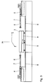
- Fig. 3
- eine schematische Seitenansicht einer Bohranlage für den Rollraum eines Rolladenkastens.
- Der Rolladenkasten umfasst ein äußeres Kastenelement (1), welches selbsttragend ausgebildet ist und eine Art inneres Kastenprofil (2), welches zusätzlich mit wärmedämmenden Material ausgestaltet werden kann.
- Bevorzugt wird der erfindungsgemäße Rolladenkasten für die Mauerdicken zwischen 20 cm und 60 cm hergestellt, jeweils mit einer bevorzugten Höhe zwischen 20 und 40 cm, einer Wanddicke zwischen 2 und 5 cm und in Längen mit bis zu 300 cm.
- Als Material dient ein armierter Porenbetonklotz (3). In Figur 1 und 2 ist erkennbar, dass der Rolladenkasten aus einem einzigen Porenbetonklotz (3) gefertigt wird.
- Die Porenbetonklötze können lediglich mit Hilfe der in Figur 3 abgebildeten speziellen Bohranlage bearbeitet werden. Diese Bohranlage besteht aus zwei stationären Bohrmaschinen (4) und (5) mit identischen Bohrwerkzeugen, wobei die Bohrwerkzeuge zueinander auf einer gemeinsamen Achse zentrisch ausgerichtet sind und die Bohrerwelle (6) in einem stabilen Rohr, dem so genannten Lagerrohr (7), gelagert ist. In den zwei einander auf einer Achse gegenüberliegenden Lagerrohren (7) ist jeweils eine Bohrvorrichtung (6) gelagert. Die Lagerrohre (7) sind mit einer Absaugeinrichtung ausgestattet und befinden sich auf ihrer Achse in einem Abstand von mehr als 2500 mm.
- Der zu bearbeitende Porenbetonklotz (3) wird auf einem sich zwischen den Bohrern befindlichen Werkzeugtisch (9) aufgelegt und in der Y-Achse und Z-Achse fixiert, wobei die X-Achse die Bohrachse darstellt. Der Tisch (9) ist auf Schienenelementen (8) in beiden X-Achsenrichtungen zu den Bohrwerkzeugen fahrbar. Zum Bohren von Langlöchern wird das Oberteil des Werkzeugtisches (9) in der Z-Achse verschoben. Der benötigte Rollraum (R) wird mittels der beschriebenen Bohrmaschinen (4, 5) durch zentrische und seitwärts angesetzte Bohrtätigkeit aufgebohrt. Die zur Ausbohrung des Rollraums führenden Bohrvorgänge finden dabei sowohl simultan als auch nicht simultan statt.
- Als weiteren Arbeitsgang werden, je nachdem ob es sich um einen geschlossenen oder offenen Rolladenkasten handelt, die Öffnung (10) auf der unteren Seite des Rolladenkastens mittels eines speziellen Bearbeitungswerkzeugs ausgeschnitten. Der Rolladenkasten wird anschließend mit der für das innere Kastenprofil (2) bestimmten zusätzlichen Dämmung, sowie den seitlichen Stirnseiten mit den Lagerhaltern und dem Gurtauslass bestückt.
- Der erfindungsgemäße Rolladenkasten verfügt aufgrund des verwendeten Materials über den Vorteil einer sehr hohe Wärmedämmung. Kaum ein anderer massiver Wand-Baustoff besitzt eine vergleichbare Wärmeleitfähigkeit wie Porenbeton. Die geringe Wärmeleitfähigkeit entsteht durch eine Vielzahl kleiner Luftporen im Porenbeton.
- Die DIN 4108 enthält Anforderungen an die Wärmedämmung und Wärmespeicherung sowie wärmeschutztechnische Hinweise für die Planung und Ausführung in der Bauphysik. Porenbeton besitzt durchweg eine geringere Wärmeleitfähigkeit als dies die Norm DIN 4108 Teil 4 fordert.
- Im so genannten inneren Kastenprofil (2) kann eine zusätzliche Wärmedämmung mittels in Form geschnittener Schaumstoffe wie Styrodur oder ähnlichen Dämmstoffen in unterschiedlichen Dicken eingebaut werden.
- Der mit der Erfindung erzielte Vorteil ist weiter darin zu sehen, dass Porenbeton ohne nennenswerte Nachteile entsorgt werden kann.
Claims (13)
- Rolladenkasten aus einem armierten Porenbetonklotz (3) als äußerem Kastenprofil (1) und einem inneren Kastenprofil (2) aus einem wärmedämmenden Material, dadurch gekennzeichnet, dass der Rollraum (R) mit Hilfe einer speziellen Bohranlage entsteht, wobei mittels zweier in einem Lagerrohr (7) gelagerter, auf einer Achse einander gegenüberliegender Bohrvorrichtungen (4, 5) zentrisch seitwärts ausgebohrt wird.
- Rolladenkasten nach Anspruch 1, dadurch gekennzeichnet, dass während der Bohrvorgänge über die Lagerrohre (7) ausgebohrtes Material abgesaugt wird.
- Rolladenkasten nach Anspruch 1 oder 2, dadurch gekennzeichnet, dass das äußere Kastenprofil (1) aus einem einzigen Porenbetonklotz (3) gefertigt ist.
- Rolladenkasten nach einem der vorgenannten Ansprüche, dadurch gekennzeichnet, dass die zur Ausbohrung des Rollraums (R) führenden Bohrvorgänge simultan stattfinden.
- Rolladenkasten nach einem der Ansprüche 1 bis 3, dadurch gekennzeichnet, dass die zur Ausbohrung des Rollraums (R) führenden Bohrvorgänge nicht simultan stattfinden.
- Rolladenkasten nach einem der vorhergehenden Ansprüche, dadurch gekennzeichnet, dass der Porenbetonklotz (3) mindestens 20 cm, maximal 40 cm hoch, mindestens 20 cm, maximal 60 cm breit ist, eine Länge bis maximal 300 cm aufweist und eine Wanddicke nach Bohrung des Rollraums (R) von mindestens 2 cm und maximal 5 cm hat.
- Vorrichtung zum Bohren des Rollraums eines Rolladenkastens nach den vorhergehenden Ansprüchen, dadurch gekennzeichnet, dass in zwei einander auf einer Achse gegenüberliegenden Lagerrohren (7) jeweils eine Bohrvorrichtung (4, 5) gelagert ist.
- Vorrichtung nach Anspruch 7, dadurch gekennzeichnet, dass die Lagerrohre (7) mit einer Absaugeinrichtung ausgestattet sind.
- Vorrichtung nach den Ansprüchen 6 oder 7, dadurch gekennzeichnet, dass zwischen den einander auf einer Achse gegenüberliegenden Lagerrohren (7) ein Abstand von mehr als 2500 mm besteht.
- Verfahren zur Herstellung eines Rolladenkastens, dadurch gekennzeichnet, dass der Rollraum (R) aus einem armierten Porenbetonklotz (3) mit Hilfe einer speziellen Bohranlage entsteht, wobei mittels zweier in einem Lagerrohr (7) gelagerter, auf einer Achse einander gegenüberliegender Bohrvorrichtungen (4, 5) zentrisch seitwärts ausgebohrt wird.
- Verfahren nach Anspruch 10, dadurch gekennzeichnet, dass während der Bohrvorgänge über die Lagerrohre (7) ausgebohrtes Material abgesaugt wird.
- Verfahren nach Anspruch 10 oder 11, dadurch gekennzeichnet, dass die zur Ausbohrung des Rollraums (R) führenden Bohrvorgänge simultan stattfinden.
- Verfahren nach Anspruch 10 oder 11, dadurch gekennzeichnet, dass die zur Ausbohrung des Rollraums (R) führenden Bohrvorgänge nicht simultan stattfinden.
Applications Claiming Priority (2)
| Application Number | Priority Date | Filing Date | Title |
|---|---|---|---|
| DE200510006453 DE102005006453B4 (de) | 2005-02-12 | 2005-02-12 | Rolladenkasten |
| DE200520003328 DE202005003328U1 (de) | 2005-03-02 | 2005-03-02 | Rolladenkasten |
Publications (3)
| Publication Number | Publication Date |
|---|---|
| EP1691027A2 true EP1691027A2 (de) | 2006-08-16 |
| EP1691027A3 EP1691027A3 (de) | 2007-09-05 |
| EP1691027B1 EP1691027B1 (de) | 2013-09-11 |
Family
ID=35929657
Family Applications (1)
| Application Number | Title | Priority Date | Filing Date |
|---|---|---|---|
| EP06002829.7A Expired - Lifetime EP1691027B1 (de) | 2005-02-12 | 2006-02-13 | Verfahren zur Herstellung eines Rolladenkasten |
Country Status (2)
| Country | Link |
|---|---|
| EP (1) | EP1691027B1 (de) |
| DK (1) | DK1691027T3 (de) |
Cited By (1)
| Publication number | Priority date | Publication date | Assignee | Title |
|---|---|---|---|---|
| CN115847141A (zh) * | 2022-12-19 | 2023-03-28 | 仙游县豪景环保有限公司 | 一种圆珠夹持机构及圆珠钻孔装置 |
Families Citing this family (1)
| Publication number | Priority date | Publication date | Assignee | Title |
|---|---|---|---|---|
| CN101695767B (zh) * | 2009-10-30 | 2011-04-06 | 石家庄丰源仪表有限公司 | 广角数控式单流表自动开孔设备 |
Family Cites Families (9)
| Publication number | Priority date | Publication date | Assignee | Title |
|---|---|---|---|---|
| DE7531525U (de) * | 1975-10-04 | 1977-03-24 | Zimmermann, Erich, 7100 Heilbronn | Vorrichtung zum ausbohren von natursteinplatten, insbesondere von treppenstufen aus naturstein |
| DE3335890A1 (de) * | 1983-10-03 | 1985-04-18 | Lindemann, Wolfgang, Dipl.-Phys. Dr.-Ing., 4800 Bielefeld | Verfahren zum bearbeiten von einen kreisfoermigen querschnitt aufweisenden oeffnungen in einem ortsfest gehaltenen festkoerper und maschinenanlage zur ausuebung des verfahrens |
| FR2603517B1 (fr) * | 1986-09-10 | 1991-05-03 | Gen Granit | Procede de fabrication de gorges et de bombes pour le batiment, notamment pour des monuments funeraires |
| DE3720837A1 (de) * | 1987-06-24 | 1987-10-15 | Wilhelm Conrads | Tieflochbohrgeraet mit laser-lichtelement gesteuerter, kontinuierlich arbeitender elektro-hydraulischer zentriervorrichtung fuer die arbeitsachse des bohrkopfes gegen auslenkung im elastischen bereich |
| JPH02109617A (ja) * | 1988-10-18 | 1990-04-23 | Inax Corp | セラミックス素地の穴加工方法及び穴加工装置 |
| AT406980B (de) * | 1995-09-05 | 2000-11-27 | Rolladen Und Sonnenschutztechn | Rolladenkasten, sowie verfahren zu seiner herstellung |
| DE29703689U1 (de) * | 1997-03-01 | 1997-05-22 | Kimm, Justus, 34576 Homberg | Haubenförmige Auffangeinrichtung für eine Bohrkrone o.dgl. zum Auffangen von Bohrmehl |
| DE29706935U1 (de) * | 1997-04-17 | 1997-11-06 | Müller, Joachim, 09669 Frankenberg | Rollokasten mit verschiedenen Vorsatzschalen auf einer Endlosfertigungsanlage hergestellt |
| JP2003071827A (ja) * | 2001-09-03 | 2003-03-12 | Sumitomo Kinzoku Kozan Siporex Kk | パネルの穿孔装置 |
-
2006
- 2006-02-13 DK DK06002829T patent/DK1691027T3/da active
- 2006-02-13 EP EP06002829.7A patent/EP1691027B1/de not_active Expired - Lifetime
Non-Patent Citations (1)
| Title |
|---|
| None |
Cited By (1)
| Publication number | Priority date | Publication date | Assignee | Title |
|---|---|---|---|---|
| CN115847141A (zh) * | 2022-12-19 | 2023-03-28 | 仙游县豪景环保有限公司 | 一种圆珠夹持机构及圆珠钻孔装置 |
Also Published As
| Publication number | Publication date |
|---|---|
| EP1691027B1 (de) | 2013-09-11 |
| DK1691027T3 (da) | 2013-12-16 |
| EP1691027A3 (de) | 2007-09-05 |
Similar Documents
| Publication | Publication Date | Title |
|---|---|---|
| DE102009023883A1 (de) | Fassadenelement | |
| WO2012052144A1 (de) | Verfahren zur einbringung von schaummaterial in hohlkammerprofile sowie hohlkammerprofile | |
| DE1509553A1 (de) | Fensterkonstruktion | |
| DE202007007517U1 (de) | Presse | |
| EP1691027B1 (de) | Verfahren zur Herstellung eines Rolladenkasten | |
| CH674234A5 (de) | ||
| EP3668734B1 (de) | Fenstervorrichtung für ein schienenfahrzeug | |
| DE102005006453B4 (de) | Rolladenkasten | |
| DE202004021567U1 (de) | Wärmedämmendes Element für Hohlräume | |
| DE202005003328U1 (de) | Rolladenkasten | |
| EP1226327B2 (de) | Verfahren zum herstellen eines türblattes sowie nach diesem verfahren herstellbares türblatt | |
| EP4006291B1 (de) | Zarge sowie fenstereinbauelement mit kompressionseinlage | |
| EP2623689B1 (de) | Holz/Beton-Verbundtragwerk mit Höhenausgleichszwischenschicht | |
| EP2556924A1 (de) | Rahmenpresse zum Verbinden von vorgefalzten Rahmenprofilen zu einem Flügelrahmen eines Fensters, einer Tür oder dergl. sowie Verfahren zum Herstellen eines solchen Flügelrahmens | |
| EP1020608B2 (de) | Verbundprofil für Rahmen von Wandelementen, Türen und Fenstern | |
| EP3995661A1 (de) | Fenster- oder türrahmen mit schiebeelementen und deren kleben ans mauerwerk sowie montageverfahren hierzu | |
| CH644667A5 (en) | Casing with window and/or door arranged in brickwork | |
| EP3862523A1 (de) | Profil | |
| EP4502443B1 (de) | Brandabschottung für leitungen in gebäuden | |
| EP2314780B1 (de) | Wärmedämmstoffplatten für wärmegedämmte hohlwandige Bauteile und Verfahren zur Verbindung von Wärmedämmstoffen. | |
| EP4127373B1 (de) | Brandschutztür | |
| EP0304829A2 (de) | Rahmen für Fenster, Türen oder dgl. und Profilstrang für seine Herstellung | |
| EP3282080B1 (de) | Rollladenschalungskasten aus porigem leichtbaumaterial | |
| EP0670411A1 (de) | Ziegel-Rolladenkasten | |
| DE69617053T2 (de) | Presse zum schäumen von isolierungsplatten |
Legal Events
| Date | Code | Title | Description |
|---|---|---|---|
| PUAI | Public reference made under article 153(3) epc to a published international application that has entered the european phase |
Free format text: ORIGINAL CODE: 0009012 |
|
| AK | Designated contracting states |
Kind code of ref document: A2 Designated state(s): AT BE BG CH CY CZ DE DK EE ES FI FR GB GR HU IE IS IT LI LT LU LV MC NL PL PT RO SE SI SK TR |
|
| AX | Request for extension of the european patent |
Extension state: AL BA HR MK YU |
|
| PUAL | Search report despatched |
Free format text: ORIGINAL CODE: 0009013 |
|
| AK | Designated contracting states |
Kind code of ref document: A3 Designated state(s): AT BE BG CH CY CZ DE DK EE ES FI FR GB GR HU IE IS IT LI LT LU LV MC NL PL PT RO SE SI SK TR |
|
| AX | Request for extension of the european patent |
Extension state: AL BA HR MK YU |
|
| RIC1 | Information provided on ipc code assigned before grant |
Ipc: B28D 1/14 20060101ALI20070802BHEP Ipc: B23B 41/00 20060101ALI20070802BHEP Ipc: E06B 9/17 20060101ALI20070802BHEP Ipc: E04F 10/00 20060101AFI20070802BHEP |
|
| RAP1 | Party data changed (applicant data changed or rights of an application transferred) |
Owner name: GREISEL BAUELEMENTE GMBH |
|
| 17P | Request for examination filed |
Effective date: 20071011 |
|
| 17Q | First examination report despatched |
Effective date: 20071220 |
|
| AKX | Designation fees paid |
Designated state(s): AT BE BG CH CY CZ DE DK EE ES FI FR GB GR HU IE IS IT LI LT LU LV MC NL PL PT RO SE SI SK TR |
|
| GRAP | Despatch of communication of intention to grant a patent |
Free format text: ORIGINAL CODE: EPIDOSNIGR1 |
|
| GRAP | Despatch of communication of intention to grant a patent |
Free format text: ORIGINAL CODE: EPIDOSNIGR1 |
|
| INTG | Intention to grant announced |
Effective date: 20130510 |
|
| GRAS | Grant fee paid |
Free format text: ORIGINAL CODE: EPIDOSNIGR3 |
|
| GRAA | (expected) grant |
Free format text: ORIGINAL CODE: 0009210 |
|
| AK | Designated contracting states |
Kind code of ref document: B1 Designated state(s): AT BE BG CH CY CZ DE DK EE ES FI FR GB GR HU IE IS IT LI LT LU LV MC NL PL PT RO SE SI SK TR |
|
| REG | Reference to a national code |
Ref country code: GB Ref legal event code: FG4D Free format text: NOT ENGLISH |
|
| REG | Reference to a national code |
Ref country code: CH Ref legal event code: EP |
|
| REG | Reference to a national code |
Ref country code: AT Ref legal event code: REF Ref document number: 631742 Country of ref document: AT Kind code of ref document: T Effective date: 20130915 |
|
| REG | Reference to a national code |
Ref country code: IE Ref legal event code: FG4D Free format text: LANGUAGE OF EP DOCUMENT: GERMAN |
|
| REG | Reference to a national code |
Ref country code: DE Ref legal event code: R096 Ref document number: 502006013187 Country of ref document: DE Effective date: 20131107 |
|
| REG | Reference to a national code |
Ref country code: DK Ref legal event code: T3 Effective date: 20131212 |
|
| PG25 | Lapsed in a contracting state [announced via postgrant information from national office to epo] |
Ref country code: CY Free format text: LAPSE BECAUSE OF FAILURE TO SUBMIT A TRANSLATION OF THE DESCRIPTION OR TO PAY THE FEE WITHIN THE PRESCRIBED TIME-LIMIT Effective date: 20130710 Ref country code: SE Free format text: LAPSE BECAUSE OF FAILURE TO SUBMIT A TRANSLATION OF THE DESCRIPTION OR TO PAY THE FEE WITHIN THE PRESCRIBED TIME-LIMIT Effective date: 20130911 Ref country code: LT Free format text: LAPSE BECAUSE OF FAILURE TO SUBMIT A TRANSLATION OF THE DESCRIPTION OR TO PAY THE FEE WITHIN THE PRESCRIBED TIME-LIMIT Effective date: 20130911 |
|
| REG | Reference to a national code |
Ref country code: NL Ref legal event code: VDEP Effective date: 20130911 |
|
| REG | Reference to a national code |
Ref country code: LT Ref legal event code: MG4D |
|
| PG25 | Lapsed in a contracting state [announced via postgrant information from national office to epo] |
Ref country code: LV Free format text: LAPSE BECAUSE OF FAILURE TO SUBMIT A TRANSLATION OF THE DESCRIPTION OR TO PAY THE FEE WITHIN THE PRESCRIBED TIME-LIMIT Effective date: 20130911 Ref country code: SI Free format text: LAPSE BECAUSE OF FAILURE TO SUBMIT A TRANSLATION OF THE DESCRIPTION OR TO PAY THE FEE WITHIN THE PRESCRIBED TIME-LIMIT Effective date: 20130911 Ref country code: FI Free format text: LAPSE BECAUSE OF FAILURE TO SUBMIT A TRANSLATION OF THE DESCRIPTION OR TO PAY THE FEE WITHIN THE PRESCRIBED TIME-LIMIT Effective date: 20130911 Ref country code: GR Free format text: LAPSE BECAUSE OF FAILURE TO SUBMIT A TRANSLATION OF THE DESCRIPTION OR TO PAY THE FEE WITHIN THE PRESCRIBED TIME-LIMIT Effective date: 20131212 |
|
| PG25 | Lapsed in a contracting state [announced via postgrant information from national office to epo] |
Ref country code: CY Free format text: LAPSE BECAUSE OF FAILURE TO SUBMIT A TRANSLATION OF THE DESCRIPTION OR TO PAY THE FEE WITHIN THE PRESCRIBED TIME-LIMIT Effective date: 20130911 |
|
| PG25 | Lapsed in a contracting state [announced via postgrant information from national office to epo] |
Ref country code: EE Free format text: LAPSE BECAUSE OF FAILURE TO SUBMIT A TRANSLATION OF THE DESCRIPTION OR TO PAY THE FEE WITHIN THE PRESCRIBED TIME-LIMIT Effective date: 20130911 Ref country code: RO Free format text: LAPSE BECAUSE OF FAILURE TO SUBMIT A TRANSLATION OF THE DESCRIPTION OR TO PAY THE FEE WITHIN THE PRESCRIBED TIME-LIMIT Effective date: 20130911 Ref country code: IS Free format text: LAPSE BECAUSE OF FAILURE TO SUBMIT A TRANSLATION OF THE DESCRIPTION OR TO PAY THE FEE WITHIN THE PRESCRIBED TIME-LIMIT Effective date: 20140111 Ref country code: NL Free format text: LAPSE BECAUSE OF FAILURE TO SUBMIT A TRANSLATION OF THE DESCRIPTION OR TO PAY THE FEE WITHIN THE PRESCRIBED TIME-LIMIT Effective date: 20130911 Ref country code: SK Free format text: LAPSE BECAUSE OF FAILURE TO SUBMIT A TRANSLATION OF THE DESCRIPTION OR TO PAY THE FEE WITHIN THE PRESCRIBED TIME-LIMIT Effective date: 20130911 Ref country code: CZ Free format text: LAPSE BECAUSE OF FAILURE TO SUBMIT A TRANSLATION OF THE DESCRIPTION OR TO PAY THE FEE WITHIN THE PRESCRIBED TIME-LIMIT Effective date: 20130911 |
|
| PG25 | Lapsed in a contracting state [announced via postgrant information from national office to epo] |
Ref country code: ES Free format text: LAPSE BECAUSE OF FAILURE TO SUBMIT A TRANSLATION OF THE DESCRIPTION OR TO PAY THE FEE WITHIN THE PRESCRIBED TIME-LIMIT Effective date: 20130911 Ref country code: PL Free format text: LAPSE BECAUSE OF FAILURE TO SUBMIT A TRANSLATION OF THE DESCRIPTION OR TO PAY THE FEE WITHIN THE PRESCRIBED TIME-LIMIT Effective date: 20130911 |
|
| REG | Reference to a national code |
Ref country code: DE Ref legal event code: R097 Ref document number: 502006013187 Country of ref document: DE |
|
| PG25 | Lapsed in a contracting state [announced via postgrant information from national office to epo] |
Ref country code: PT Free format text: LAPSE BECAUSE OF FAILURE TO SUBMIT A TRANSLATION OF THE DESCRIPTION OR TO PAY THE FEE WITHIN THE PRESCRIBED TIME-LIMIT Effective date: 20140113 |
|
| PLBE | No opposition filed within time limit |
Free format text: ORIGINAL CODE: 0009261 |
|
| STAA | Information on the status of an ep patent application or granted ep patent |
Free format text: STATUS: NO OPPOSITION FILED WITHIN TIME LIMIT |
|
| 26N | No opposition filed |
Effective date: 20140612 |
|
| PG25 | Lapsed in a contracting state [announced via postgrant information from national office to epo] |
Ref country code: IT Free format text: LAPSE BECAUSE OF FAILURE TO SUBMIT A TRANSLATION OF THE DESCRIPTION OR TO PAY THE FEE WITHIN THE PRESCRIBED TIME-LIMIT Effective date: 20130911 |
|
| REG | Reference to a national code |
Ref country code: DE Ref legal event code: R097 Ref document number: 502006013187 Country of ref document: DE Effective date: 20140612 |
|
| PG25 | Lapsed in a contracting state [announced via postgrant information from national office to epo] |
Ref country code: MC Free format text: LAPSE BECAUSE OF FAILURE TO SUBMIT A TRANSLATION OF THE DESCRIPTION OR TO PAY THE FEE WITHIN THE PRESCRIBED TIME-LIMIT Effective date: 20130911 |
|
| REG | Reference to a national code |
Ref country code: CH Ref legal event code: PL |
|
| GBPC | Gb: european patent ceased through non-payment of renewal fee |
Effective date: 20140213 |
|
| PG25 | Lapsed in a contracting state [announced via postgrant information from national office to epo] |
Ref country code: LI Free format text: LAPSE BECAUSE OF NON-PAYMENT OF DUE FEES Effective date: 20140228 Ref country code: CH Free format text: LAPSE BECAUSE OF NON-PAYMENT OF DUE FEES Effective date: 20140228 |
|
| REG | Reference to a national code |
Ref country code: FR Ref legal event code: ST Effective date: 20141031 |
|
| REG | Reference to a national code |
Ref country code: IE Ref legal event code: MM4A |
|
| PG25 | Lapsed in a contracting state [announced via postgrant information from national office to epo] |
Ref country code: IE Free format text: LAPSE BECAUSE OF NON-PAYMENT OF DUE FEES Effective date: 20140213 Ref country code: FR Free format text: LAPSE BECAUSE OF NON-PAYMENT OF DUE FEES Effective date: 20140228 Ref country code: GB Free format text: LAPSE BECAUSE OF NON-PAYMENT OF DUE FEES Effective date: 20140213 |
|
| REG | Reference to a national code |
Ref country code: AT Ref legal event code: MM01 Ref document number: 631742 Country of ref document: AT Kind code of ref document: T Effective date: 20140213 |
|
| PG25 | Lapsed in a contracting state [announced via postgrant information from national office to epo] |
Ref country code: AT Free format text: LAPSE BECAUSE OF NON-PAYMENT OF DUE FEES Effective date: 20140213 |
|
| PG25 | Lapsed in a contracting state [announced via postgrant information from national office to epo] |
Ref country code: BG Free format text: LAPSE BECAUSE OF FAILURE TO SUBMIT A TRANSLATION OF THE DESCRIPTION OR TO PAY THE FEE WITHIN THE PRESCRIBED TIME-LIMIT Effective date: 20130911 |
|
| PG25 | Lapsed in a contracting state [announced via postgrant information from national office to epo] |
Ref country code: TR Free format text: LAPSE BECAUSE OF FAILURE TO SUBMIT A TRANSLATION OF THE DESCRIPTION OR TO PAY THE FEE WITHIN THE PRESCRIBED TIME-LIMIT Effective date: 20130911 Ref country code: HU Free format text: LAPSE BECAUSE OF FAILURE TO SUBMIT A TRANSLATION OF THE DESCRIPTION OR TO PAY THE FEE WITHIN THE PRESCRIBED TIME-LIMIT; INVALID AB INITIO Effective date: 20060213 |
|
| PGFP | Annual fee paid to national office [announced via postgrant information from national office to epo] |
Ref country code: DK Payment date: 20200220 Year of fee payment: 15 |
|
| PGFP | Annual fee paid to national office [announced via postgrant information from national office to epo] |
Ref country code: LU Payment date: 20200220 Year of fee payment: 15 Ref country code: BE Payment date: 20200220 Year of fee payment: 15 |
|
| PGFP | Annual fee paid to national office [announced via postgrant information from national office to epo] |
Ref country code: DE Payment date: 20210426 Year of fee payment: 16 |
|
| REG | Reference to a national code |
Ref country code: DK Ref legal event code: EBP Effective date: 20210228 |
|
| REG | Reference to a national code |
Ref country code: BE Ref legal event code: MM Effective date: 20210228 |
|
| PG25 | Lapsed in a contracting state [announced via postgrant information from national office to epo] |
Ref country code: LU Free format text: LAPSE BECAUSE OF NON-PAYMENT OF DUE FEES Effective date: 20210213 |
|
| PG25 | Lapsed in a contracting state [announced via postgrant information from national office to epo] |
Ref country code: DK Free format text: LAPSE BECAUSE OF NON-PAYMENT OF DUE FEES Effective date: 20210228 |
|
| PG25 | Lapsed in a contracting state [announced via postgrant information from national office to epo] |
Ref country code: BE Free format text: LAPSE BECAUSE OF NON-PAYMENT OF DUE FEES Effective date: 20210228 |
|
| REG | Reference to a national code |
Ref country code: DE Ref legal event code: R119 Ref document number: 502006013187 Country of ref document: DE |
|
| PG25 | Lapsed in a contracting state [announced via postgrant information from national office to epo] |
Ref country code: DE Free format text: LAPSE BECAUSE OF NON-PAYMENT OF DUE FEES Effective date: 20220901 |