EP1691109A2 - Integrierte Riemenspannvorrichtung - Google Patents
Integrierte Riemenspannvorrichtung Download PDFInfo
- Publication number
- EP1691109A2 EP1691109A2 EP06250730A EP06250730A EP1691109A2 EP 1691109 A2 EP1691109 A2 EP 1691109A2 EP 06250730 A EP06250730 A EP 06250730A EP 06250730 A EP06250730 A EP 06250730A EP 1691109 A2 EP1691109 A2 EP 1691109A2
- Authority
- EP
- European Patent Office
- Prior art keywords
- belt
- pulley
- tension
- tensioning device
- indicator
- Prior art date
- Legal status (The legal status is an assumption and is not a legal conclusion. Google has not performed a legal analysis and makes no representation as to the accuracy of the status listed.)
- Withdrawn
Links
Images

Classifications
-
- G—PHYSICS
- G11—INFORMATION STORAGE
- G11B—INFORMATION STORAGE BASED ON RELATIVE MOVEMENT BETWEEN RECORD CARRIER AND TRANSDUCER
- G11B33/00—Constructional parts, details or accessories not provided for in the other groups of this subclass
- G11B33/12—Disposition of constructional parts in the apparatus, e.g. of power supply, of modules
- G11B33/125—Disposition of constructional parts in the apparatus, e.g. of power supply, of modules the apparatus comprising a plurality of recording/reproducing devices, e.g. modular arrangements, arrays of disc drives
-
- B—PERFORMING OPERATIONS; TRANSPORTING
- B65—CONVEYING; PACKING; STORING; HANDLING THIN OR FILAMENTARY MATERIAL
- B65G—TRANSPORT OR STORAGE DEVICES, e.g. CONVEYORS FOR LOADING OR TIPPING, SHOP CONVEYOR SYSTEMS OR PNEUMATIC TUBE CONVEYORS
- B65G23/00—Driving gear for endless conveyors; Belt- or chain-tensioning arrangements
- B65G23/44—Belt or chain tensioning arrangements
-
- G—PHYSICS
- G11—INFORMATION STORAGE
- G11B—INFORMATION STORAGE BASED ON RELATIVE MOVEMENT BETWEEN RECORD CARRIER AND TRANSDUCER
- G11B15/00—Driving, starting or stopping record carriers of filamentary or web form; Driving both such record carriers and heads; Guiding such record carriers or containers therefor; Control thereof; Control of operating function
- G11B15/675—Guiding containers, e.g. loading, ejecting cassettes
- G11B15/68—Automatic cassette changing arrangements; automatic tape changing arrangements
-
- F—MECHANICAL ENGINEERING; LIGHTING; HEATING; WEAPONS; BLASTING
- F16—ENGINEERING ELEMENTS AND UNITS; GENERAL MEASURES FOR PRODUCING AND MAINTAINING EFFECTIVE FUNCTIONING OF MACHINES OR INSTALLATIONS; THERMAL INSULATION IN GENERAL
- F16H—GEARING
- F16H7/00—Gearings for conveying rotary motion by endless flexible members
- F16H7/08—Means for varying tension of belts, ropes or chains
- F16H2007/0861—Means for varying tension of belts, ropes or chains comprising means for sensing tensioner position
Definitions
- Various aspects and examples relate generally to belt drive systems, and more particularly to integrated belt tensioning devices and associated methods, which may advantageously be used with automated storage libraries.
- Belt drive systems typically include a motor driven belt spanning between two or more pulleys.
- the tension of the belt in the belt drive system is important for the performance and operation of the belt drive system as well as the wear and period of life of the belt.
- the belt drive system may operate poorly or wear excessively with incorrect tension.
- belt drive systems generally operate with a desired tension (or within a desired range). Measuring and adjusting the tension of a belt in a belt drive system generally requires external measuring devices, e.g., force meters or the like, access to various portions of the belt drive system, and skilled technicians to determine and adjust the tension.
- One exemplary method for adjusting the tension in a belt drive system includes a force displacement method where the belt is displaced near a midpoint of the span by a predetermined distance using a force gauge.
- the force gauge reading may be used to determine the tension in the belt (alternatively, the belt may be displaced by predetermined force and the distance of displacement correlated to a tension value).
- the belt may be adjusted based on the force gauge reading, and tension measurement(s) repeated until a desired tension of the belt is achieved.
- Another exemplary method for adjusting the tension in a belt drive system includes a frequency method where the belt is set vibrating, and the frequency is measured electronically with a frequency meter and correlated to tension in the belt.
- the frequency meter is placed at the mid point between the two pulleys.
- Automated storage libraries generally include a housing having plurality of storage bins or slots for holding storage devices (such as magnetic or optical devices), a robotic cartridge gripping mechanism (often referred to as a "picker"), and one or more media drives.
- the robotic picker may be controlled to select a specific storage device from the library and transfer the storage device between a storage slot and a media drive within seconds.
- the robotic picker typically includes a gripper or hand mechanism positioned on the robotic picker.
- the robotic picker may position the gripper near a desired storage device and activate the gripper to engage or grip the storage device to remove the storage device from the storage bin.
- the robotic arm may move the gripper and storage device to a location to load the storage device into a media drive, load port (for adding or removing storage devices from the library), and the like.
- a cross-link mechanism may include a picker mechanism or pocket driven by a belt drive system, which cooperates with the library system picker to selectively transport storage cartridges from one storage library to another.
- the picker mechanism associated with the cross-link mechanism desirably moves with a fairly high degree of precision and repeatability to access and transport storage devices.
- the operation and precision of the cross-link mechanism may be improved by ensuring that the belt driving the picker mechanism has a tension value within desired tolerances, and that the belt tension value remain substantially constant over time. For example, if the tension varies from a desired value, the precision of the cross-link mechanism may suffer as well as the life of the belt drive system associated with the cross-link mechanism. Accordingly, the tension in the belt is desirably set upon installation and easily measured and adjusted over time to remain within desired tolerances.
- a belt tensioning device in one example described herein, includes a pulley, a biasing member, and an indicator.
- the biasing member e.g., a spring or the like
- the indicator is associated with the position of the pulley and varies according to the relative position of the pulley to the biased position. For example, increased tension from a belt acting on the pulley displaces the pulley away from the biased position, against the biasing force.
- the indicator varies according to the relative position of the pulley from the biased position and may thereby be correlated to the tension in the belt system.
- the belt tensioning device including, for example, the biasing member, pulley, and indicator, may be configured for particular belt drive systems and desired belt tension values.
- the indicator may be configured to indicate a desired tension or may be graduated to indicate various tension values.
- the indicator may include various suitable elements to visually indicate the displacement of the pulley (or other relatively moving portions of the belt tensioning device which may be correlated to tension in the belt system). For example, various indicia, markings, windows, or other suitable visual cues associated with various positions of relatively moving portions of the belt tensioning device may be used to indicate tension in the belt system.
- the cross-link mechanism includes a belt spanning between two or more pulleys and a belt tensioning device.
- the belt tensioning device may include a first pulley, a biasing member coupled to the first pulley to bias the pulley in a biased position, and an indicator associated with the pulley, wherein the pulley is configured such that tension in the belt displaces the first pulley away from the biased position, and the indicator varies according to the displacement of the first pulley.
- a method for tensioning a belt within a belt drive system includes biasing a pulley of the belt drive system such that as tension in the belt increases the pulley moves away from the biased positioned.
- An indicator associated with the relative position of the pulley may be used to correlate the displacement of the pulley to a tension in the belt.
- a belt is positioned to span between two or more pulleys.
- One of the pulleys is included with a belt tensioning device, the belt tensioning device including the pulley, a biasing member to bias the pulley, and an indicator associated with the relative position of the pulley.
- the belt tensioning assembly is adjusted to tension the belt between the two or more pulleys.
- the indicator may be observed to indicate the tension in the belt and the belt tensioning assembly may be repositioned to vary the tension in the belt.
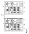
- Figure 1 illustrates two exemplary storage library systems coupled by a cross-link mechanism, the cross-link mechanism including a belt tensioning device according to one example;
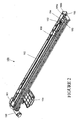
- Figure 2 illustrates an exemplary cross-link-mechanism including a belt tensioning device in greater detail
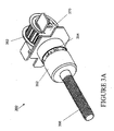
- Figures 3A and 3B illustrate a perspective and exploded illustration of an exemplary belt tensioning device
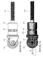
- Figures 4A and 4B illustrate side views of an exemplary belt tensioning device under varying load conditions
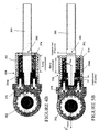
- Figures 5A and 5B illustrate cross-sectional side views of an exemplary belt tensioning device under varying load conditions.
- a belt drive system including an integrated, self-contained belt tensioning device.
- the belt tensioning device may be integrated within the belt drive system, e.g., at least a portion of the belt tensioning device, such as a pulley, is part of the belt drive system.
- the belt tensioning device includes a pulley that engages the belt during operation of the belt drive system.
- the belt tensioning device may be moved to adjust the tension in the belt.
- the pulley is biased in a direction (e.g., away from the belt) by a biasing member (e.g., a spring) such that as tension in the belt is increased, the pulley moves relative to the belt tensioning device and against the biasing force.
- a biasing member e.g., a spring
- An indicator may be associated with the tensioning device to iridicate the displacement of the pulley from its biased position as tension in the belt is increased.
- the displacement of the pulley may be correlated (based on, e.g., the biasing force, the distance of displacement, etc.) to a tension value in the belt. Accordingly, the indicator may allow a user to visually inspect and ensure proper tension in the belt without additional gauges or instruments.
- the indicator may include any suitable indicia, marks, devices, or the like associated with relative moving portions of the belt tensioning assembly to indicate tension in the belt.
- Exemplary belt drive systems and belt tensioning assemblies are described herein generally with respect to automated storage libraries and mechanisms for linking multiple automated storage libraries. These descriptions and examples are illustrative only of several applications of the exemplary belt drive systems and belt tensioning assemblies; those of ordinary skill in the art will recognize that the exemplary belt drive systems and belt tensioning assemblies may be used in a variety of other applications and technologies including belt drive systems not specifically mentioned herein.
- FIG. 1 is a schematic illustration of two exemplary automated storage library systems 100 for the storage and retrieval of a plurality of storage devices 114 stored therein.
- Storage library systems 100 include one or more media drives 112, a plurality of storage devices 114 stored in bins or storage slots 116, and a transport mechanism 118 that may be equipped with a picker mechanism (not shown) for transporting selected storage devices 114, for example, between a drive 112 and a storage slot 116.
- Storage library systems 100 further includes a library controller 104 that communicates with a host processor or computer network to control the actions of transport mechanism 118 and drives 112 to retrieve and/or store data.
- Automated storage library systems 100 may further include various other features such as load ports for manually adding and removing storage devices to and from the library, various access doors, control panels, power supplies, and the like as are known in the art. For clarity, however, such additional features have been omitted from the description.
- Storage library systems 100 may further transfer storage devices 114 from one library system 100 to an adjacent library system 100 via cross-link mechanism 150. Accordingly, cross-link mechanism 150 allows two or more storage library systems 100 to share storage devices 114 by loading a cartridge onto cross-link mechanism 150 and transferring device 114 to a new location within an adjacent storage library system 100.
- Exemplary cross-link mechanism 150 includes a belt drive motor system as shown in greater detail in Figure 2.
- cross-link mechanism 150 generally includes track 152 for guiding a picker mechanism 154 (which may include any suitable device for engaging or holding one or more storage devices).
- Picker mechanism 154 is driven by a belt motor system including motor 156 and belt 158 spanning between pulleys 161 and 162.
- the belt motor system includes a belt tensioning device 160 including pulley 162, a tension indicator 164, and an adjustment screw 166.
- the belt tensioning device 160 is adjustatily fixed to a frame member of track 152 via adjustment screw 166 and nuts 166a and 166b.
- tension indicator 164 provides a visual indication of the force on pulley 162 associated with the tension in belt 158.
- belt tensioning device 160 includes a biasing member (not shown in Figure 2).
- Belt 158 is driven by motor 156 and spans between pulley 161 associated with motor 156 and pulley 162 of belt tensioning device 160.
- Belt tensioning device 160 may be adjusted via adjustment screw 166 and nuts 166a and 166b to adjust the position of pulley 162 and the tension in belt 158. Moving belt tensioning device 160 away from belt 158 (to the right, away from pulley 161) increases tension in belt 158 and shifting belt tensioning device 160 toward belt 158 (to the left, toward pulley 161) decreases tension in belt 158.
- pulley 162 of belt tensioning device 160 is biased in a direction away from pulley 161 and the direction of tension force produced by belt 158 on pulley 162.
- the biasing force is such to offset a desired tension in belt 158.
- tension in belt 158 will overcome the biasing force acting on pulley 162 such that pulley 162 will move relative to tensioning device 160.
- the tension in belt 158 results in a displacement of pulley 162 relative to adjustment screw 166 and generally opposite the biasing force direction. The displacement provides an indication of the tension force in belt 158.
- the displacement of pulley 162 relative to the biased positioned of pulley 162 may be observed via a tension indicator 164 associated with tensioning device 160.
- the tension indicator 164 may include any suitable indicator associated with the displacement or relative tension in belt 158. For example, a distinguishable color, marking, or other feature may be used to indicate the displacement and tension value.
- the tension indicator 164, pulley 162, and biasing force may all be adapted for a desired tension force in belt 158. Accordingly, a user may view tension indicator 164 and adjust adjustment screw 166 to vary the position of belt tensioning device 160 and the tension of belt 158 to a desired level.
- adjustment screw 166 is attached to a frame portion of track 152 via two nuts 166a and 166b.
- the outer nut 166b is rotated to adjust the position of pulley 162 and the inner nut 166a is rotated to lock or unlock adjustment screw 166 in place with respect to the track 152.
- various other configurations and suitable elements may be used to adjust the position of pulley 162 and/or secure belt tensioning device 160 to a frame member.
- belt 158 includes a "tooth belt” or synchronous belt. In other examples, belt 158 may include a friction belt.
- a belt drive system may include more than two pulleys, and more than one belt tensioning device. Additionally, it is possible to associate or include a belt tensioning device with a pulley that is also associated with a driving motor.
- the exemplary tensioning device 160 and cross-link mechanism 150 provides a belt drive system that may be installed and the tension in belt 158 measure and adjusted with a reduced need for specialized tools, measuring devices, or special technical skills. Additionally, the tension of belt 158 may be viewed and adjusted over time with reduced complexity.
- Figures 3A, 3B, 4A, 4B, 5A, and 5B illustrate in greater detail an exemplary belt tensioning device 360, which is similar to belt tensioning device 160 shown in Figure 2.
- Figure 3A and 3B illustrate a perspective view and exploded view of belt tensioning device 360.
- Figures 4A, 4B, 5A, and 5B illustrate side and cross-sectional views of exemplary belt tensioning device 360 under varying levels of force from a belt, and are referenced in combination with Figures 3A and 3B.
- Belt tensioning device 360 generally includes pulley 362, pulley bracket 370, housing 352, biasing member 374, tension indicator including inspection window 354 and washer 354a, threaded adjustment rod 366, as well as various other washers, lock nuts, and the like for securing the belt tensioning device 360.
- Threaded adjustment screw 366 is adapted to pass through a frame portion to secure belt tensioning device 360 within a system and is captivated by two lock nuts (for example, similar to lock nuts 166a and 166b of Figure 2). The lock nuts may be tightened and loosened appropriately to move and secure belt tensioning device 360 in a desired location relative to other portions of a belt drive system.
- belt tensioning device 360 is initially positioned to remove slack in the belt, e.g., by rotating one of the nuts associated with adjustment screw 366. Continuing to move belt tensioning device 360 increases tension on the belt and compresses biasing member 374, e.g., a coil spring or the like, this in turn moves washer 354a in view of aperture or inspection window 354 of housing 357.
- biasing member 374 and position of the tension indicator washer 354a and inspection window 354 may be arranged such that a desired belt tension value is achieved when the indicator washer 354a is centered with (and therefore visible through) inspection window 354.
- biasing member 374 may be designed with predetermined load, e.g., a 16 pound load, such that when the indicator washer 354a is aligned with inspection window 354, tension in the belt is approximately equal to the preset load.
- the location of inspection window 354, washer 354a, the biasing force of biasing member 374, and other features of belt tensioning device 360 may be varied depending on various factors such as the particular application, desired tension in the belt, desired tolerances, and the like.
- the tensioning device 360 may be locked in place; for example, by locking a nut or other element to hold belt tensioning device 360 in place with respect to a frame member or the like.
- tensioning device 360 is positioned to remove slack from a belt and create a desired tension force in the belt
- pulley 362 is displaced relative to adjustment screw 366.
- biasing member 374 is compressed, thereby displacing washer 354a with respect to housing 374 such that washer 354a is visible through inspection window 354.
- multiple inspection windows 354 are shown circumferentially around housing 352; such a configuration allows a user to view washer 354a from various positions relative to belt tensioning device 360.
- washer 354a may include a color varying from that of housing 352 to be clearly visible to a user.
- the visual indicator may be configured in a variety of fashions. In some examples, multiple apertures may be included in housing 352 to provide a graduated inspection window associated with varying tension levels of the associated belt. Additionally, in other examples, markings 390 (see Figures 4B and 5B) may be included on adjustment screw 366, which may used to determine the displacement of housing 352. Generally, an indicator may include any suitable indicia to reference any two moving parts of belt tensioning system 360 associated with relative displacement of pulley 162 against biasing member 374 when the belt is under sufficient tension.
- the motor and belt tension device may be positioned adjacent the same pulley.
- Multiple belt tensioning devices may be included within a single belt drive system, and the like.
Landscapes
- Engineering & Computer Science (AREA)
- Mechanical Engineering (AREA)
- Automatic Tape Cassette Changers (AREA)
- Devices For Conveying Motion By Means Of Endless Flexible Members (AREA)
- Drives For Endless Conveyors (AREA)
Applications Claiming Priority (1)
| Application Number | Priority Date | Filing Date | Title |
|---|---|---|---|
| US11/057,685 US20060183585A1 (en) | 2005-02-11 | 2005-02-11 | Integrated belt tensioning devices and associated methods |
Publications (2)
| Publication Number | Publication Date |
|---|---|
| EP1691109A2 true EP1691109A2 (de) | 2006-08-16 |
| EP1691109A3 EP1691109A3 (de) | 2006-11-22 |
Family
ID=36178034
Family Applications (1)
| Application Number | Title | Priority Date | Filing Date |
|---|---|---|---|
| EP06250730A Withdrawn EP1691109A3 (de) | 2005-02-11 | 2006-02-10 | Integrierte Riemenspannvorrichtung |
Country Status (3)
| Country | Link |
|---|---|
| US (1) | US20060183585A1 (de) |
| EP (1) | EP1691109A3 (de) |
| JP (1) | JP2006220305A (de) |
Cited By (2)
| Publication number | Priority date | Publication date | Assignee | Title |
|---|---|---|---|---|
| EP3336553A1 (de) * | 2012-03-29 | 2018-06-20 | Biomérieux Inc. | System und verfahren zur einrichtung und/oder aufrechterhaltung der korrekten ausrichtung eines robotischen transportmechanismus |
| DE102021203698A1 (de) | 2021-04-14 | 2022-10-20 | Wolfgang Rixen | Spannvorrichtung |
Families Citing this family (6)
| Publication number | Priority date | Publication date | Assignee | Title |
|---|---|---|---|---|
| KR100810610B1 (ko) * | 2006-10-25 | 2008-03-07 | 삼성전자주식회사 | 벨트장력 조절장치 및 이를 갖는 로봇암 |
| US8550763B2 (en) * | 2010-09-30 | 2013-10-08 | International Business Machines Corporation | Cell engagement and retention carriage |
| CH708587A1 (de) * | 2013-09-16 | 2015-03-31 | M Tanner Ag | Klemmförderer mit zumindest einer Spanneinheit. |
| US10435092B2 (en) | 2016-10-13 | 2019-10-08 | The Charles Machine Works, Inc. | Track tensioner |
| US10918019B2 (en) * | 2018-07-02 | 2021-02-16 | Cnh Industrial America Llc | System for adjusting the conveyor belt tension force within an agricultural harvester |
| US10962428B1 (en) * | 2020-03-27 | 2021-03-30 | Reliability Concepts LLC | Belt tension measuring system and method |
Family Cites Families (39)
| Publication number | Priority date | Publication date | Assignee | Title |
|---|---|---|---|---|
| US2161046A (en) * | 1936-03-27 | 1939-06-06 | David C Rockola | Parking meter |
| US3603416A (en) * | 1970-05-18 | 1971-09-07 | Fmc Corp | Weighing apparatus for belt conveyor |
| DE2047092B1 (de) * | 1970-09-24 | 1971-12-23 | Aristo Werke Dennert & Pape Kg | Bandantrieb |
| US3992932A (en) * | 1974-10-24 | 1976-11-23 | Borg-Warner Corporation | Torque measuring system |
| US4068535A (en) * | 1975-11-10 | 1978-01-17 | David L. Ray | Method and apparatus for controlling the tension of drive belts |
| US4172569A (en) * | 1977-01-12 | 1979-10-30 | Newell Research Corporation | Tape transport system with peripheral belt drive |
| DE2811199A1 (de) * | 1978-03-15 | 1979-09-20 | Klippan Nv | Vorrichtung zur belastungsanzeige einer unter zugspannung bringbaren halteeinrichtung |
| US4186598A (en) * | 1978-08-23 | 1980-02-05 | Borroughs Tool & Equipment Corporation | Belt tension gauge |
| CH631013A5 (de) * | 1978-09-20 | 1982-07-15 | Schmid Roost J Sro Kugellagerw | Messvorrichtung. |
| US4517795A (en) * | 1979-11-28 | 1985-05-21 | Deere & Company | Bale-shape gauge for baler for forming cylindrical bales |
| US4444065A (en) * | 1981-03-05 | 1984-04-24 | Borroughs Tool & Equipment Corporation | Belt tension gauge |
| US4576041A (en) * | 1984-06-11 | 1986-03-18 | Texaco Inc. | Dynamic balancing means for an oil well pumping unit |
| US4650161A (en) * | 1984-11-30 | 1987-03-17 | Daiwa Seiko Inc. | Spinning reel having electronic line tension display means |
| US5064192A (en) * | 1990-03-26 | 1991-11-12 | Smith Arthur A | Exercising indicator |
| US5030173A (en) * | 1990-03-28 | 1991-07-09 | Bryant Charles B | Spring loaded telescopic tube take-up |
| JPH04143959A (ja) * | 1990-10-05 | 1992-05-18 | Mitsubishi Electric Corp | ディスク記憶装置 |
| US5111808A (en) * | 1990-11-29 | 1992-05-12 | Bissell Healthcare Corporation | Foot elevator blanket cradle |
| US5226359A (en) * | 1992-03-10 | 1993-07-13 | Vermeer Manufacturing Company | Bale size indicator |
| FR2690492B1 (fr) * | 1992-04-28 | 1994-07-22 | Colmant Cuvelier | Courroie de transmission a temoin de tension de montage incorpore. |
| US5546665A (en) * | 1994-03-17 | 1996-08-20 | Jackmauh; John A. | Motorcycle rear wheel alignment system |
| EP0765521A1 (de) * | 1994-06-15 | 1997-04-02 | Imation Corp. | Motorsteuerung von bandspannung in einer riemenkassette |
| US5570337A (en) * | 1994-11-07 | 1996-10-29 | International Business Machines Corporation | Modular independent libraries interconnected by a common media exchange and input apparatus |
| US5761890A (en) * | 1995-06-26 | 1998-06-09 | New Holland North America, Inc. | Disc mower with modular cutterbar |
| GB9601075D0 (en) * | 1996-01-19 | 1996-03-20 | Alliedsignal Ltd | Pretensioner |
| US5769747A (en) * | 1996-09-05 | 1998-06-23 | Deere & Company | Belt tensioning mechanism with stop feature |
| JP3610700B2 (ja) * | 1996-10-09 | 2005-01-19 | ソニー株式会社 | テープカセット記録及び/又は再生装置 |
| US6003657A (en) * | 1996-12-02 | 1999-12-21 | Asgco Manufacturing, Inc. | Self-indicating tensioner for a belt scraper |
| WO1999028652A2 (en) * | 1997-11-26 | 1999-06-10 | Litens Automotive Partnership | Rotary belt tensioner with hydraulic damping |
| US6165089A (en) * | 1998-04-15 | 2000-12-26 | Mcgreal; Timothy R. | Transmission apparatus and method |
| US6030305A (en) * | 1998-09-28 | 2000-02-29 | Ingersoll-Rand Company | Semi-automatic tensioner for a belt drive system |
| US6438623B1 (en) * | 1999-04-16 | 2002-08-20 | Ampex Corporation | Transfer unit extending between two or more cabinets for expansion of tape library systems |
| JP4390336B2 (ja) * | 1999-12-17 | 2009-12-24 | セイコーエプソン株式会社 | キャリッジベルトのテンション調整装置 |
| JP4521624B2 (ja) * | 2000-07-31 | 2010-08-11 | 日本発條株式会社 | テンショナー |
| US6854415B2 (en) * | 2001-06-29 | 2005-02-15 | Finecard International Limited | Seat belt tension sensing device |
| US6609987B1 (en) * | 2001-10-01 | 2003-08-26 | General Motors Corporation | Hydraulic timing chain tensioner assembly |
| JP3897334B2 (ja) * | 2001-12-28 | 2007-03-22 | 株式会社椿本チエイン | プランジャの突出防止機能を有するテンショナ |
| US20030153419A1 (en) * | 2002-02-12 | 2003-08-14 | Yahya Hodjat | Tensioning idler |
| US6849011B2 (en) * | 2002-11-23 | 2005-02-01 | International Truck Intellectual Property Company, Llc | Engine endless drive belt tensioner and tensioner position indicator |
| US6852049B2 (en) * | 2003-01-24 | 2005-02-08 | Borgwarner Inc. | Ratcheting hydraulic chain tensioner with rotational reset and locking means |
-
2005
- 2005-02-11 US US11/057,685 patent/US20060183585A1/en not_active Abandoned
-
2006
- 2006-02-10 JP JP2006033927A patent/JP2006220305A/ja not_active Withdrawn
- 2006-02-10 EP EP06250730A patent/EP1691109A3/de not_active Withdrawn
Cited By (3)
| Publication number | Priority date | Publication date | Assignee | Title |
|---|---|---|---|---|
| EP3336553A1 (de) * | 2012-03-29 | 2018-06-20 | Biomérieux Inc. | System und verfahren zur einrichtung und/oder aufrechterhaltung der korrekten ausrichtung eines robotischen transportmechanismus |
| AU2017200525B2 (en) * | 2012-03-29 | 2019-02-14 | BIOMéRIEUX, INC. | System And Method For Establishing And/Or Maintaining Proper Alignment Of A Robotic Transfer Mechanism |
| DE102021203698A1 (de) | 2021-04-14 | 2022-10-20 | Wolfgang Rixen | Spannvorrichtung |
Also Published As
| Publication number | Publication date |
|---|---|
| JP2006220305A (ja) | 2006-08-24 |
| EP1691109A3 (de) | 2006-11-22 |
| US20060183585A1 (en) | 2006-08-17 |
Similar Documents
| Publication | Publication Date | Title |
|---|---|---|
| US4957471A (en) | Adjustable locked center and dynamic tensioner | |
| EP1691109A2 (de) | Integrierte Riemenspannvorrichtung | |
| US5064405A (en) | Adjustable locked center and dynamic tensioner | |
| US20090151182A1 (en) | Measuring device | |
| EP0919798A2 (de) | Torsionsfederklassifizierung mittels Hysterese-Mittelwertbildung | |
| DK2691577T3 (en) | MEASURING SYSTEM FOR pole | |
| US20230034869A1 (en) | Multi-dimensional sheave for use in tension measurement systems | |
| US12392645B2 (en) | Magnet fixing implement | |
| US20040156062A1 (en) | Adjustable sensor assembly for printers | |
| US6454254B2 (en) | Sheet mounting apparatus | |
| US6154976A (en) | Measuring device | |
| KR20200093022A (ko) | 인장계 구조체 | |
| US6467184B1 (en) | Measuring apparatus provided with a stylus | |
| US6622827B1 (en) | Elevator tape guide with tape slot redundancy | |
| US6813112B2 (en) | Method, apparatus and software for tape drive mechanical fault detection | |
| EP0708442B1 (de) | Plattenspeicherung und -wiederauffindung | |
| US11512762B2 (en) | Right angle mechanical actuator for tensioner | |
| KR102219215B1 (ko) | 길이측정장치 | |
| US7388806B2 (en) | Mass positioning apparatus for a seismic sensor | |
| JP5930537B2 (ja) | クリアランス調整機構を有するリニアエンコーダおよびリニアエンコーダのクリアランス調整方法 | |
| KR100238493B1 (ko) | 비디오 테이프 카세트 케이스의 마찰실험장치 | |
| KR200467193Y1 (ko) | 접촉형 진동센서 스트로크 조정장치 | |
| US7911204B2 (en) | Reel shaft of barcode printer | |
| JP2004198268A (ja) | 駆動機構制御装置及び対象物処理装置 | |
| JPH0412215A (ja) | レンズ型板の形状計測装置 |
Legal Events
| Date | Code | Title | Description |
|---|---|---|---|
| PUAI | Public reference made under article 153(3) epc to a published international application that has entered the european phase |
Free format text: ORIGINAL CODE: 0009012 |
|
| AK | Designated contracting states |
Kind code of ref document: A2 Designated state(s): AT BE BG CH CY CZ DE DK EE ES FI FR GB GR HU IE IS IT LI LT LU LV MC NL PL PT RO SE SI SK TR |
|
| AX | Request for extension of the european patent |
Extension state: AL BA HR MK YU |
|
| PUAL | Search report despatched |
Free format text: ORIGINAL CODE: 0009013 |
|
| AK | Designated contracting states |
Kind code of ref document: A3 Designated state(s): AT BE BG CH CY CZ DE DK EE ES FI FR GB GR HU IE IS IT LI LT LU LV MC NL PL PT RO SE SI SK TR |
|
| AX | Request for extension of the european patent |
Extension state: AL BA HR MK YU |
|
| 17P | Request for examination filed |
Effective date: 20070402 |
|
| 17Q | First examination report despatched |
Effective date: 20070510 |
|
| AKX | Designation fees paid |
Designated state(s): DE GB |
|
| STAA | Information on the status of an ep patent application or granted ep patent |
Free format text: STATUS: THE APPLICATION IS DEEMED TO BE WITHDRAWN |
|
| 18D | Application deemed to be withdrawn |
Effective date: 20090429 |